CN214268198U - Reciprocating type end sealing mechanism - Google Patents
Reciprocating type end sealing mechanism Download PDFInfo
- Publication number
- CN214268198U CN214268198U CN202022899100.6U CN202022899100U CN214268198U CN 214268198 U CN214268198 U CN 214268198U CN 202022899100 U CN202022899100 U CN 202022899100U CN 214268198 U CN214268198 U CN 214268198U
- Authority
- CN
- China
- Prior art keywords
- plate
- sealing
- shaft
- sliding
- transverse plate
- Prior art date
- Legal status (The legal status is an assumption and is not a legal conclusion. Google has not performed a legal analysis and makes no representation as to the accuracy of the status listed.)
- Active
Links
- 238000007789 sealing Methods 0.000 title claims abstract description 93
- 230000007246 mechanism Effects 0.000 title claims abstract description 26
- 238000010438 heat treatment Methods 0.000 claims abstract description 33
- 230000005540 biological transmission Effects 0.000 claims abstract description 20
- 238000005520 cutting process Methods 0.000 claims abstract description 17
- 230000007704 transition Effects 0.000 claims abstract description 16
- 239000003638 chemical reducing agent Substances 0.000 claims description 11
- 230000003139 buffering effect Effects 0.000 claims description 9
- 230000006698 induction Effects 0.000 claims description 5
- 230000033001 locomotion Effects 0.000 abstract description 9
- 230000000694 effects Effects 0.000 abstract description 8
- 238000004806 packaging method and process Methods 0.000 description 14
- 238000000034 method Methods 0.000 description 4
- 230000009471 action Effects 0.000 description 3
- 230000008569 process Effects 0.000 description 3
- 230000009286 beneficial effect Effects 0.000 description 2
- 230000008602 contraction Effects 0.000 description 2
- 230000007547 defect Effects 0.000 description 2
- 238000010030 laminating Methods 0.000 description 2
- 239000000463 material Substances 0.000 description 2
- 238000012986 modification Methods 0.000 description 2
- 230000004048 modification Effects 0.000 description 2
- 238000000926 separation method Methods 0.000 description 2
- 230000000903 blocking effect Effects 0.000 description 1
- 230000006835 compression Effects 0.000 description 1
- 238000007906 compression Methods 0.000 description 1
- 238000010586 diagram Methods 0.000 description 1
- 239000000428 dust Substances 0.000 description 1
- 239000012535 impurity Substances 0.000 description 1
- 238000012536 packaging technology Methods 0.000 description 1
Images


Landscapes
- Package Closures (AREA)
Abstract
The utility model discloses a reciprocating end sealing mechanism, which comprises a machine base, a driving device, a cam component, a connecting rod component, an upper sealing cutting die, a lower sealing cutting die and an adjusting component, wherein the transmission of power is realized by adopting chain transmission, so that the transmission efficiency is stable, and the starting and stopping are stable; the utility model adopts the transition gear to drive, and adds the cam component and the connecting rod component, thereby playing the role of stable motion and greatly reducing the noise when the equipment runs; in addition, adopt the piece that generates heat to replace the heating tube to the portion that generates heat, the piece that generates heat is bigger than the heating surface of heating tube, plays and generates heat evenly, seals the even effect of being heated, has promoted the involution effect of wrapping bag.
Description
Technical Field
The utility model relates to the field of packaging technology, more specifically say, in particular to reciprocating type end seals mechanism.
Background
The end sealing device is an important component on a packaging machine, when the packaging machine works, packaging bag paper is firstly formed into a packaging bag model through the packaging machine, then materials are filled, the packaging bag is moved to the longitudinal sealing device to seal the side face, then the packaging bag is moved to the end sealing device, the end portion of the packaging bag is sealed and cut off, and packaging of the materials is achieved. In the existing automatic packaging device, a reciprocating end sealing mechanism is mostly adopted, the closing of an upper sealing cutter module and a lower sealing cutter module is realized through the reciprocating motion of the mechanism, and the sealing and cutting processes are simultaneously completed. The reciprocating type end sealing packaging machine commonly used at present has the defects of excessively rigid reciprocating motion form and high operation noise. In addition, the heat generated during heat sealing is not uniform, which results in the defect that the sealing of the seal is not uniform enough.
SUMMERY OF THE UTILITY MODEL
The utility model provides a reciprocating type end seals mechanism to solve the problem that proposes among the above-mentioned background art. In order to achieve the above object, the utility model provides a following technical scheme: a reciprocating end sealing mechanism comprises a machine base, a driving device, a cam assembly, a connecting rod assembly, an upper sealing cutting die, a lower sealing cutting die and an adjusting assembly;
a driving gear, a transition gear and a rotating gear are sequentially arranged on two side edges of the base from bottom to top, and the driving gear, the transition gear and the rotating gear are in meshed connection; the driving wheels on two sides of the machine base are connected through a rotating shaft, and a driven chain wheel and an induction device are arranged on the rotating shaft; the driven chain wheel is in transmission connection with the driving device through a chain; the driving gear and the rotating gear are respectively provided with a first eccentric shaft and a second eccentric shaft;
the cam component comprises a pair of cam plates which are oppositely arranged, and four corners of the two cam plates are fixed in the base through guide rods; a connecting shaft is arranged between the two cam plates, the cam plates are provided with curve grooves, and the connecting shaft is connected to the curve grooves through bearings; a support arm is arranged on the connecting shaft; one end of the support arm is connected with the connecting shaft, and the other end of the support arm is rotatably connected with the lower cutter sealing die; the driving device is arranged on one cam plate through a bracket;
the connecting rod assembly comprises a connecting arm, a sliding rod, an upper sliding block, a lower sliding block and a side plate; an upper through hole and a lower chute are respectively arranged at two ends of the connecting arm, the first eccentric shaft is connected with the upper through hole, and the second eccentric shaft is connected with the lower chute; the sliding rod is fixedly connected with the connecting arm through a pair of clamping blocks, and the upper sliding block and the lower sliding block are slidably sleeved on the sliding rod; the side plate is arranged on the outer side of the sliding rod and is fixedly connected with the sliding rod;
the upper knife sealing die comprises a buffering assembly and a knife sealing assembly, the end part of the buffering assembly is fixedly connected with the top of the sliding rod, and the end part of the knife sealing assembly is connected with the upper sliding block;
the end part of the lower knife sealing die is connected with the lower sliding block;
the adjusting component comprises an upper supporting plate, a lower supporting plate, a long screw rod and a short screw rod; the upper supporting plate is connected with the top of the machine base, and the lower supporting plate is connected with the bottom of the machine base; the upper part of the long screw rod is rotationally connected with the upper supporting plate and is provided with a hand wheel, and the lower part of the long screw rod is in threaded connection with the lower supporting plate and is provided with a first chain wheel; the upper part of the short screw rod is rotatably connected with the upper supporting plate, and the lower part of the short screw rod is in threaded connection with the lower supporting plate and is provided with a second chain wheel; the first chain wheel is connected with the second chain wheel through a chain.
Preferably, the buffer assembly comprises a first transverse plate, and the end part of the first transverse plate is fixedly connected with the top of the slide rod; a pair of spring shafts is arranged on the first transverse plate, and a buffer plate is arranged between the two spring shafts; the buffer plate is provided with a pair of first sliding shafts, two ends of the buffer plate are respectively and rotatably connected with a first connecting plate, and a second connecting plate and a third connecting plate are rotatably connected to the first connecting plate;
the knife sealing assembly comprises a second transverse plate, and the end part of the second transverse plate is fixedly connected with the upper sliding block; a tool sealing seat is arranged below the second transverse plate, and upper heating devices are respectively arranged on two sides of the tool sealing seat; the first sliding shaft is respectively connected with the first transverse plate and the second transverse plate in a sliding manner; the second connecting plate is fixedly connected with the first transverse plate, and the third connecting plate is fixedly connected with the second transverse plate; the spring shaft comprises a pressure spring and a second sliding shaft, the bottom end of the second sliding shaft is fixedly connected with the second transverse plate, the other end of the second sliding shaft is connected with the first transverse plate in a sliding mode, the pressure spring is sleeved in the second sliding shaft, and the two ends of the pressure spring are respectively in contact with the first transverse plate and the second transverse plate.
Preferably, the lower knife sealing die comprises a third transverse plate, and the end part of the third transverse plate is fixedly connected with the lower sliding block; and a heat sealing seat is arranged on the third transverse plate, and lower heating devices are arranged on two sides of the heat sealing seat.
Preferably, the upper heating device and the lower heating device are both heating sheets.
Preferably, the upper slider and the lower slider are both linear bearings.
Preferably, induction system is including origin dish, fixing base, cell type switch and switch seat, the fixing base passes through the bolt chucking in the pivot and with the pivot has same center pin, origin dish fixed mounting in on the fixing base, the cell type switch passes through the switch seat install in on the frame, the cell type switch with origin dish cooperation sets up.
Preferably, still including locating the backplate at frame top, the both sides perk that makes progress of backplate, the middle part is equipped with and supplies the first logical groove that the support arm passes through, it is equipped with the apron on the logical groove, be equipped with on the apron and supply the second that the support arm passes through leads to the groove.
Preferably, the driving device comprises a servo motor and a speed reducer, an output shaft of the servo motor is connected with the speed reducer, a driving sprocket is arranged on an output shaft of the speed reducer, and the driving sprocket is in transmission connection with the driven sprocket through a chain.
Compared with the prior art, the beneficial effects of the utility model are that: the utility model discloses at the during operation, at first drive arrangement starts, later drive the driving gear through chain drive, then the driving gear transmission is to transition gear, transition gear transmission is to drive transmitting gear, first eccentric shaft and second eccentric shaft on transmitting gear and the driving gear drive simultaneously and link the arm and link each subassembly on the wall and carry out reciprocal swing, go up to seal the cutting die and seal the cutting die down and realize laminating and separation through cam assembly and link assembly, realize sealing and the cut-off function of wrapping bag then. The utility model realizes the transmission of power by adopting chain transmission, has stable transmission efficiency and stable start and stop; in addition, the utility model adopts the transition gear to drive, and adds the cam component and the connecting rod component, so as to play the role of stable movement and greatly reduce the noise when the equipment runs; in addition, adopt the piece that generates heat to replace the heating tube to the portion that generates heat, the piece that generates heat is bigger than the heating surface of heating tube, plays and generates heat evenly, seals the even effect of being heated, has promoted the involution effect of wrapping bag.
Drawings
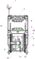
FIG. 1 is a front view of a reciprocating end seal mechanism according to an embodiment of the present invention;
FIG. 2 is a block diagram of a reciprocating end seal mechanism according to an embodiment of the present invention;
FIG. 3 is a back view of a reciprocating end seal mechanism according to an embodiment of the present invention;
FIG. 4 is a side view of a reciprocating end seal mechanism according to an embodiment of the present invention;
FIG. 5 is a side cross-sectional view of a reciprocating end seal mechanism in accordance with an embodiment of the present invention;
in fig. 1 to 5, the corresponding relationship between the names of the components and the reference numbers is as follows:
1-machine base, 2-driving device, 201-servo motor, 202-speed reducer, 203-driving chain wheel, 3-cam assembly, 301-cam plate, 3011-curve groove, 302-guide rod, 303-connecting shaft, 304-supporting arm, 4-connecting rod assembly, 401-connecting arm, 4011-lower sliding groove, 402-sliding rod, 403-upper sliding block, 404-lower sliding block, 405-side plate, 5-upper knife sealing die, 501-first transverse plate, 502-spring shaft, 5021-pressure spring, 5022-second sliding shaft, 503-buffer plate, 504-first sliding shaft, 505-first connecting plate, 201-servo motor, 202-speed reducer, 203-driving chain wheel, 3-cam assembly, 301-cam plate, 3011-curve groove, 302-guide rod, 303-connecting shaft, 304-supporting arm, 401-connecting arm, 4011-lower sliding groove, 402-sliding rod, 403-upper knife sealing die, 501-first transverse plate, 502-spring shaft, 5021-pressure spring, 5022-second sliding shaft, 503-buffer plate, 504-first sliding shaft, 505-first connecting plate, 505-second connecting plate, and the like, 506-a second connecting plate, 507-a third connecting plate, 508-a second transverse plate, 509-a knife sealing seat, 5010-an upper heating device, 6-a lower knife sealing die, 601-a third transverse plate, 602-a heat sealing seat, 603-a lower heating device, 7-an adjusting component, 701-an upper supporting plate, 702-a lower supporting plate, 703-a long lead screw, 704-a short lead screw, 705-a hand wheel, 706-a first chain wheel, 707-a second chain wheel, 8-a driving gear, 9-a transition gear, 10-a rotating gear, 11-a rotating shaft, 12-a driven chain wheel, 13-an induction device, 1301-an origin plate, a rotating shaft, 12-a driven chain wheel, 1302-fixed seat, 1303-slot type switch, 1304-switch seat, 14-first eccentric shaft, 15-second eccentric shaft, 16-guard plate, 17-cover plate.
Detailed Description
The following describes embodiments of the present invention in further detail with reference to the accompanying drawings and examples. The following examples are intended to illustrate the invention, but are not intended to limit the scope of the invention.
In the description of the present invention, "a plurality" means two or more unless otherwise specified; the terms "upper", "lower", "left", "right", "inner", "outer", "front", "rear", "head", "tail", and the like indicate orientations or positional relationships based on the orientations or positional relationships shown in the drawings, and are merely for convenience of description and simplicity of description, and do not indicate or imply that the device or element being referred to must have a particular orientation, be constructed and operated in a particular orientation, and thus, should not be construed as limiting the present invention. Furthermore, the terms "first," "second," "third," and the like are used for descriptive purposes only and are not to be construed as indicating or implying relative importance.
In the description of the present invention, it is to be noted that, unless otherwise explicitly specified or limited, the terms "connected" and "connected" are to be interpreted broadly, and may be, for example, fixedly connected, detachably connected, or integrally connected; can be mechanically or electrically connected; may be directly connected or indirectly connected through an intermediate. The specific meaning of the above terms in the present invention can be understood in specific cases to those skilled in the art.
Referring to fig. 1 to 5, the present invention provides a reciprocating end sealing mechanism, which includes a machine base 1, a driving device 2, a cam assembly 3, a connecting rod assembly 4, an upper sealing cutter die 5, a lower sealing cutter die 6 and an adjusting assembly 7;
two side edges of the base 1 are sequentially provided with a driving gear 8, a transition gear 9 and a rotating gear 10 from bottom to top, and the driving gear 8, the transition gear 9 and the rotating gear 10 are in meshed connection; the driving wheels on two sides of the machine base 1 are connected through a rotating shaft 11, and a driven chain wheel 12 and an induction device 13 are arranged on the rotating shaft 11; the driven chain wheel 12 is in transmission connection with the driving device 2 through a chain; the driving gear 8 and the rotating gear 10 are respectively provided with a first eccentric shaft 14 and a second eccentric shaft 15;
the cam component 3 comprises a pair of cam plates 301 which are oppositely arranged, and four corners of the two cam plates 301 are fixed in the machine base 1 through guide rods 302; a connecting shaft 303 is arranged between the two cam plates 301, the cam plates 301 are provided with a curve groove 3011, and the connecting shaft 303 is connected to the curve groove 3011 through a bearing; a support arm 304 is arranged on the connecting shaft 303; one end of the support arm 304 is connected with the connecting shaft 303, and the other end of the support arm is rotatably connected with the lower knife sealing die 6; the driving device 2 is arranged on one cam plate 301 through a bracket;
the connecting rod assembly 4 comprises a connecting arm 401, a sliding rod 402, an upper sliding block 403, a lower sliding block 404 and a side plate 405; an upper through hole and a lower chute 4011 are respectively arranged at two ends of the connecting arm 401, the first eccentric shaft 14 is connected with the upper through hole, and the second eccentric shaft 15 is connected with the lower chute 4011; the slide bar 402 is fixedly connected with the connecting arm 401 through a pair of clamping blocks, and the upper slide block 403 and the lower slide block 404 are slidably sleeved on the slide bar 402; the side plate 405 is arranged on the outer side of the sliding rod 402 and is fixedly connected with the sliding rod 402;
the upper knife sealing die 5 comprises a buffering component and a knife sealing component, the end part of the buffering component is fixedly connected with the top of the sliding rod 402, and the end part of the knife sealing component is connected with the upper sliding block 403;
the end part of the lower knife sealing die 6 is connected with the lower sliding block 404;
the adjusting component 7 comprises an upper supporting plate 701, a lower supporting plate 702, a filament rod 703 and a short filament rod 704; the upper supporting plate 701 is connected with the top of the machine base 1, and the lower supporting plate 702 is connected with the bottom of the machine base 1; the upper part of the long screw rod 703 is rotationally connected with the upper supporting plate 701 and is provided with a hand wheel 705, and the lower part of the long screw rod is in threaded connection with the lower supporting plate 702 and is provided with a first chain wheel 706; the upper part of the short screw rod 704 is rotatably connected with the upper supporting plate 701, and the lower part of the short screw rod is in threaded connection with the lower supporting plate 702 and is provided with a second chain wheel 707; the first chain wheel 706 is connected with the second chain wheel 707 through a chain.
The utility model discloses an in the embodiment, the during operation, drive arrangement 2 starts to drive driven sprocket 12 through the chain and rotate, driven sprocket 12 drives pivot 11 and rotates, drives the driving gear 8 rotation at 11 both ends of pivot then. Then the driving gear 8 is transmitted to the transition gear 9, the transition gear 9 is transmitted to the rotating gear 10, and the rotating gear 10 and the first eccentric shaft 14 and the second eccentric shaft 15 on the driving gear 8 drive the connecting arm 401 to perform up-and-down reciprocating swing with a certain radian while performing eccentric motion. The connecting arm 401 moves to drive the sliding rod 402 connected with the connecting arm to move together, all components on the sliding rod 402 also move along with the connecting arm, specifically, the upper sealing cutter die 5 moves up and down along with the sliding rod 402, and when the upper sealing cutter die moves down, the upper sealing cutter die can be matched with the lower sealing cutter die 6 to process the packaging bag; because the lower cutting sealing die 6 is connected with the support arm 304, the motion track of the lower cutting sealing die 6 is limited by the cam component 3. In the cam component 3, a pair of cam plates 301 is a key for limiting the motion trail of the lower knife sealing die 6, a curve groove 3011 is arranged on the side surface of the cam plate 301, the lower half part of the curve groove 3011 is arc-shaped, and the upper half part is linear; the two cam plates 301 act on the connecting shaft 303 at the same time, the connecting shaft 303 is fixedly connected with the bottom end of the supporting arm 304, the other end of the supporting arm 304 is rotatably connected with the lower knife sealing die 6, therefore, the lower knife sealing die 6 is limited by the supporting arm 304 when moving along with the sliding rod 402, the lower part of the supporting arm 304 is limited by the connecting shaft 303, finally, the lower part of the supporting arm 304 moves along with the shape of the curved slot 3011, under the limitation of the curved slot 3011, when the upper knife sealing die 5 moves downwards along with the sliding rod 402, the lower knife sealing die 6 moves upwards along with the sliding rod 402 under the action of the supporting arm 304, finally, the upper knife sealing die 5 and the lower knife sealing die 6 are butted, and the operation of heating sealing and cutting off the package is started. After the completion of the operation, as the driving device 2 continues to operate, when the upper sealing cutter die 5 moves upward along with the slide bar 402, the lower sealing cutter die 6 moves downward along the slide bar 402 under the action of the arm 304, and finally the upper sealing cutter die 5 and the lower sealing cutter die 6 return to the initial positions to prepare for the next sealing and cutting operation. In this embodiment, the whole mechanism can be adjusted in height by an adjusting device, specifically, the structure of the long screw rod 703 and the short screw rod 704 is as shown in the drawing, the lower half part is a screw structure, and the upper half part is a smooth structure; when the positions of the long screw rod 703 and the short screw rod 704 are kept stable, when the hand wheel 705 is rotated, the hand wheel 705 drives the long screw rod 703 to rotate, the long screw rod 703 drives the short screw rod 704 to rotate together, and under the combined action of the long screw rod 703 and the short screw rod 704, the machine base 1 starts to move upwards or downwards along the screw rod part, so that the height position of the whole mechanism is adjusted.
Preferably, the buffering assembly comprises a first horizontal plate 501, and an end of the first horizontal plate 501 is fixedly connected with the top of the sliding rod 402; a pair of spring shafts 502 is arranged on the first transverse plate 501, and a buffer plate 503 is arranged between the two spring shafts 502; the buffer plate 503 is provided with a pair of first sliding shafts 504, two ends of the buffer plate 503 are respectively rotatably connected with a first connecting plate 505, and a second connecting plate 506 and a third connecting plate 507 are rotatably connected to the first connecting plate 505;
the knife sealing assembly comprises a second transverse plate 508, and the end part of the second transverse plate 508 is fixedly connected with the upper sliding block 403; a tool sealing seat 509 is arranged below the second transverse plate 508, and two sides of the tool sealing seat 509 are respectively provided with an upper heating device 5010; the first sliding shaft 504 is slidably connected to the first horizontal plate 501 and the second horizontal plate 508 respectively; the second connecting plate 506 is fixedly connected with the first transverse plate 501, and the third connecting plate 507 is fixedly connected with the second transverse plate 508; the spring shaft 502 comprises a pressure spring 5021 and a second sliding shaft 5022, the bottom end of the second sliding shaft 5022 is fixedly connected with the second transverse plate 508, the other end of the second sliding shaft 5022 is slidably connected with the first transverse plate 501, the pressure spring 5021 is sleeved in the second sliding shaft 5022, and two ends of the pressure spring 5021 are respectively in contact with the first transverse plate 501 and the second transverse plate 508.
The utility model discloses an in the embodiment, carry out the in-process of pressfitting at a sword subassembly, the buffering subassembly plays the cushioning effect for the end seals the process more steady. The buffer assembly mainly achieves a buffer function through two aspects, one is a spring shaft 502 which performs buffering through contraction of a pressure spring 5021, the other is a buffer plate 503 which achieves slow descending through rotation of three connecting plates, and the compression spring 5021 is more stable in the contraction process. When the upper sealing cutter die 5 is butted with the lower sealing cutter die 6, heat sealing and cutting are mainly realized through the sealing cutter assembly, the packaging bag is heated through the upper heating device 5010 on the sealing cutter seat 509, and the packaging bag is cut through the cutter.
Preferably, the lower cutting sealing die 6 includes a third transverse plate 601, and an end of the third transverse plate 601 is fixedly connected with the lower slider 404; a heat sealing seat 602 is arranged on the third transverse plate 601, and lower heating devices 603 are arranged on two sides of the heat sealing seat 602.
Preferably, the upper heating device 5010 and the lower heating device 603 are both heating sheets. In the embodiment, a heating sheet is adopted to replace a heating pipe in the transmission end sealing mechanism; from the heating mode, the heating plate heats more evenly than the heating pipe, and the heating surface is bigger, and can dispel the heat comparatively fast, and the energy efficiency is higher.
Preferably, the upper slider 403 and the lower slider 404 are both linear bearings.
Preferably, the sensing device 13 includes an origin plate 1301, a fixed seat 1302, a slot switch 1303 and a switch seat 1304, the fixed seat 1302 is fastened to the rotating shaft 11 through a bolt and has a same central axis with the rotating shaft 11, the origin plate 1301 is fixedly installed on the fixed seat 1302, the slot switch 1303 is installed on the base 1 through the switch seat 1304, and the slot switch 1303 is disposed in cooperation with the origin plate 1301. Through setting up fixing base 1302 with pivot 11 pivoted simultaneously for initial point dish 1301 can rotate with pivot 11 synchronization, and slot type switch 1303 is slotted photoelectric switch in the middle of the U type, and through the slot in the middle of slot type switch 1303, zero setting through initial point dish 1301 and slot type switch 1303's cooperation is used for realizing the motor when initial point dish 1301 rotates, reaches drive arrangement 2's position calibration's effect.
Preferably, the support frame further comprises a protection plate 16 arranged at the top of the base, two sides of the protection plate 16 are tilted upwards, a first through groove for the support arm 304 to pass through is formed in the middle of the protection plate, a cover plate 17 is arranged on the through groove, and a second through groove for the support arm 304 to pass through is formed in the cover plate 17. Through the structural design, the length of the first through groove is long, the support arm 304 can freely move in the first through groove, and the length of the second through groove is consistent with the size of the support arm 304, so that the support arm 304 can drive the cover plate 17 to slide back and forth above the first through groove during movement to just seal the first through groove, and thus a guard plate 16 mechanism capable of blocking dust or sundries above is formed. The one-piece shield 16 can be formed with an inclined configuration so that the impurities slide to designated collection points.
Preferably, the driving device 2 includes a servo motor 201 and a speed reducer 202, an output shaft of the servo motor 201 is connected to the speed reducer 202, a driving sprocket 203 is disposed on an output shaft of the speed reducer 202, and the driving sprocket 203 is connected to the driven sprocket 12 through a chain transmission.
Compared with the prior art, the beneficial effects of the utility model are that: the utility model discloses at the during operation, at first drive arrangement starts, later drive the driving gear through chain drive, then the driving gear transmission is to transition gear, transition gear transmission is to drive transmitting gear, first eccentric shaft and second eccentric shaft on transmitting gear and the driving gear drive simultaneously and link the arm and link each subassembly on the wall and carry out reciprocal swing, go up to seal the cutting die and seal the cutting die down and realize laminating and separation through cam assembly and link assembly, realize sealing and the cut-off function of wrapping bag then. The utility model realizes the transmission of power by adopting chain transmission, has stable transmission efficiency and stable start and stop; in addition, the utility model adopts the transition gear to drive, and adds the cam component and the connecting rod component, so as to play the role of stable movement and greatly reduce the noise when the equipment runs; in addition, adopt the piece that generates heat to replace the heating tube to the portion that generates heat, the piece that generates heat is bigger than the heating surface of heating tube, plays and generates heat evenly, seals the even effect of being heated, has promoted the involution effect of wrapping bag.
The embodiments of the present invention have been presented for purposes of illustration and description, and are not intended to be exhaustive or limited to the invention in the form disclosed. Many modifications and variations will be apparent to those of ordinary skill in the art. The embodiment was chosen and described in order to best explain the principles of the invention and the practical application, and to enable others of ordinary skill in the art to understand the invention for various embodiments with various modifications as are suited to the particular use contemplated.
Claims (8)
1. A reciprocating end sealing mechanism is characterized by comprising a machine base (1), a driving device (2), a cam assembly (3), a connecting rod assembly (4), an upper sealing cutting die (5), a lower sealing cutting die (6) and an adjusting assembly (7);
two side edges of the base are sequentially provided with a driving gear (8), a transition gear (9) and a rotating gear (10) from bottom to top, and the driving gear, the transition gear and the rotating gear are in meshed connection; the driving wheels on two sides of the machine base are connected through a rotating shaft (11), and a driven chain wheel (12) and an induction device (13) are arranged on the rotating shaft; the driven chain wheel is in transmission connection with the driving device through a chain; the driving gear and the rotating gear are respectively provided with a first eccentric shaft (14) and a second eccentric shaft (15);
the cam component comprises a pair of cam plates (301) which are oppositely arranged, and four corners of the two cam plates are fixed in the machine base through guide rods (302); a connecting shaft (303) is arranged between the two cam plates, the cam plates are provided with curve grooves (3011), and the connecting shaft is connected to the curve grooves through bearings; a support arm (304) is arranged on the connecting shaft; one end of the support arm is connected with the connecting shaft, and the other end of the support arm is rotatably connected with the lower cutter sealing die; the driving device is arranged on one cam plate through a bracket;
the connecting rod assembly comprises a connecting arm (401), a sliding rod (402), an upper sliding block (403), a lower sliding block (404) and a side plate (405); an upper through hole and a lower chute (4011) are respectively arranged at two ends of the connecting arm, the first eccentric shaft is connected with the upper through hole, and the second eccentric shaft is connected with the lower chute; the sliding rod is fixedly connected with the connecting arm through a pair of clamping blocks, and the upper sliding block and the lower sliding block are slidably sleeved on the sliding rod; the side plate is arranged on the outer side of the sliding rod and is fixedly connected with the sliding rod;
the upper knife sealing die comprises a buffering assembly and a knife sealing assembly, the end part of the buffering assembly is fixedly connected with the top of the sliding rod, and the end part of the knife sealing assembly is connected with the upper sliding block;
the end part of the lower knife sealing die is connected with the lower sliding block;
the adjusting component comprises an upper supporting plate (701), a lower supporting plate (702), a filament rod (703) and a short filament rod (704); the upper supporting plate is connected with the top of the machine base, and the lower supporting plate is connected with the bottom of the machine base; the upper part of the long screw rod is rotationally connected with the upper supporting plate and is provided with a hand wheel (705), and the lower part of the long screw rod is in threaded connection with the lower supporting plate and is provided with a first chain wheel (706); the upper part of the short screw rod is rotationally connected with the upper supporting plate, and the lower part of the short screw rod is in threaded connection with the lower supporting plate and is provided with a second chain wheel (707); the first chain wheel is connected with the second chain wheel through a chain.
2. The reciprocating end sealing mechanism according to claim 1, wherein the buffer assembly comprises a first transverse plate (501), and an end of the first transverse plate is fixedly connected with the top of the slide bar; a pair of spring shafts (502) is arranged on the first transverse plate, and a buffer plate (503) is arranged between the two spring shafts; the buffer plate is provided with a pair of first sliding shafts (504), two ends of the buffer plate are respectively and rotatably connected with a first connecting plate (505), and a second connecting plate (506) and a third connecting plate (507) are rotatably connected to the first connecting plate;
the knife sealing assembly comprises a second transverse plate (508), and the end part of the second transverse plate is fixedly connected with the upper sliding block; a tool sealing seat (509) is arranged below the second transverse plate, and two sides of the tool sealing seat are respectively provided with an upper heating device (5010); the first sliding shaft is respectively connected with the first transverse plate and the second transverse plate in a sliding manner; the second connecting plate is fixedly connected with the first transverse plate, and the third connecting plate is fixedly connected with the second transverse plate; the spring shaft comprises a pressure spring (5021) and a second sliding shaft (5022), the bottom end of the second sliding shaft is fixedly connected with the second transverse plate, the other end of the second sliding shaft is in sliding connection with the first transverse plate, the pressure spring is sleeved in the second sliding shaft, and the two ends of the pressure spring are respectively in contact with the first transverse plate and the second transverse plate.
3. The reciprocating end sealing mechanism according to claim 2, wherein the lower sealing knife mold comprises a third transverse plate (601), and the end of the third transverse plate is fixedly connected with the lower sliding block; and a heat sealing seat (602) is arranged on the third transverse plate, and lower heating devices (603) are arranged on two sides of the heat sealing seat.
4. The reciprocating end seal mechanism of claim 3 wherein said upper heating means and said lower heating means are both heat fins.
5. The reciprocating end seal mechanism of claim 1 wherein said upper slide and said lower slide are both linear bearings.
6. The reciprocating end sealing mechanism according to claim 1, wherein the sensing device comprises a origin plate (1301), a fixed seat (1302), a slot switch (1303) and a switch seat (1304), the fixed seat is clamped on the rotating shaft through a bolt and has the same central axis with the rotating shaft, the origin plate is fixedly installed on the fixed seat, the slot switch is installed on the base through the switch seat, and the slot switch is matched with the origin plate.
7. The reciprocating end sealing mechanism according to any one of claims 1 to 6, further comprising a guard plate (16) disposed on the top of the machine base, wherein two sides of the guard plate are tilted upward, a first through groove for the support arm to pass through is disposed in the middle of the guard plate, a cover plate (17) is disposed on the through groove, and a second through groove for the support arm to pass through is disposed on the cover plate.
8. The reciprocating end seal mechanism according to claim 7, wherein the driving device comprises a servo motor (201) and a speed reducer (202), an output shaft of the servo motor is connected with the speed reducer, a driving sprocket (203) is arranged on an output shaft of the speed reducer, and the driving sprocket is in transmission connection with the driven sprocket through a chain.
Applications Claiming Priority (2)
| Application Number | Priority Date | Filing Date | Title |
|---|---|---|---|
| CN2020224578334 | 2020-10-29 | ||
| CN202022457833 | 2020-10-29 |
Publications (1)
| Publication Number | Publication Date |
|---|---|
| CN214268198U true CN214268198U (en) | 2021-09-24 |
Family
ID=77779496
Family Applications (1)
| Application Number | Title | Priority Date | Filing Date |
|---|---|---|---|
| CN202022899100.6U Active CN214268198U (en) | 2020-10-29 | 2020-12-04 | Reciprocating type end sealing mechanism |
Country Status (1)
| Country | Link |
|---|---|
| CN (1) | CN214268198U (en) |
-
2020
- 2020-12-04 CN CN202022899100.6U patent/CN214268198U/en active Active
Similar Documents
| Publication | Publication Date | Title |
|---|---|---|
| CN112847471B (en) | A rubber slicing device | |
| CN104787389B (en) | Bagging apparatus on bean noodles automatic packaging machine | |
| CN214818831U (en) | Cutting device of semi-automatic film plastic uptake machine | |
| CN221986807U (en) | Thermal shrinkage packaging side film cutting machine | |
| CN213229292U (en) | Knife sealing device suitable for packaging machine | |
| CN212373780U (en) | High-speed traditional Chinese medicine decoction pieces packet packaging machine | |
| CN209937056U (en) | Rice noodle cutting machine | |
| CN110182411B (en) | Blood bag packaging machine and working method thereof | |
| CN116495248B (en) | Sealing machine with uninterrupted continuous sealing effect | |
| CN216784068U (en) | High-speed horizontal sealing device | |
| CN224198092U (en) | Thermoplastic sealing machine for packaging bag production | |
| CN214931186U (en) | Linked multi-sealing device | |
| CN213263170U (en) | Sealing and cutting device for composite packaging film | |
| CN222022298U (en) | Welding sealing device | |
| CN211544112U (en) | High-speed intelligent pillow type packaging machine | |
| CN209905221U (en) | Double-transverse sealing structure of reciprocating type packaging machine | |
| CN224225407U (en) | Vacuum pumping clamping device of bag feeding type packaging machine | |
| CN224225453U (en) | Bag taking and compressing device of automatic cement bag inserting machine | |
| CN223046049U (en) | A high-speed pillow-type automatic packaging machine | |
| CN220263402U (en) | Film clamping and pulling device | |
| CN216128530U (en) | Rotary upper and lower end seal | |
| CN219383077U (en) | Double-end sealing opening cutting device of packing machine | |
| CN219383052U (en) | Ball screw end sealing device of packing machine | |
| CN117585252B (en) | Bag taking mechanism capable of achieving three-direction movement | |
| CN223685439U (en) | A robotic arm motion control device for a bag clamping machine |
Legal Events
| Date | Code | Title | Description |
|---|---|---|---|
| GR01 | Patent grant | ||
| GR01 | Patent grant |