CN214267428U - Bus handrail convenient to grip - Google Patents
Bus handrail convenient to grip Download PDFInfo
- Publication number
- CN214267428U CN214267428U CN202023289356.1U CN202023289356U CN214267428U CN 214267428 U CN214267428 U CN 214267428U CN 202023289356 U CN202023289356 U CN 202023289356U CN 214267428 U CN214267428 U CN 214267428U
- Authority
- CN
- China
- Prior art keywords
- central
- handle
- sliding
- plate
- spring
- Prior art date
- Legal status (The legal status is an assumption and is not a legal conclusion. Google has not performed a legal analysis and makes no representation as to the accuracy of the status listed.)
- Active
Links
- 230000000149 penetrating effect Effects 0.000 claims 1
- 230000002093 peripheral effect Effects 0.000 abstract description 3
- 238000000034 method Methods 0.000 description 5
- 238000005381 potential energy Methods 0.000 description 4
- 238000009825 accumulation Methods 0.000 description 1
- 230000004075 alteration Effects 0.000 description 1
- 230000009286 beneficial effect Effects 0.000 description 1
- 238000010586 diagram Methods 0.000 description 1
- 238000012986 modification Methods 0.000 description 1
- 230000004048 modification Effects 0.000 description 1
- 238000006467 substitution reaction Methods 0.000 description 1
Images


Landscapes
- Rehabilitation Tools (AREA)
Abstract
The utility model relates to the technical field of bus handrails, in particular to a bus handrail convenient to hold, which comprises a handrail body and a handle, wherein the bottom end of the handrail body is provided with the handle, the handle comprises handle side edges, a central fixed block, sliding side plates, a central rod, a first spring, a central sliding plate, a rotating connecting plate and a second spring, the central fixed block is arranged between the handle side edges at the front side and the rear side, the sliding side plates are all connected with the inner sides of the front end and the rear end of the central fixed block in a sliding way, the central rod is fixedly connected between the central fixed blocks at the upper side and the lower side, the central sliding plate is connected with the outer end surface of the central rod in a sliding way, the rotating connecting plate is connected with the front end and the rear end of the central sliding plate in a rotating way, in the utility model, through the arranged handle, when part of women or adult users use, the handles at the front side and the rear side can be pressed relatively, the length of the peripheral surface of the handle is reduced, so that the handle is convenient for a user with a small palm to hold.
Description
Technical Field
The utility model relates to a bus handrail technical field specifically is a bus handrail convenient to grip.
Background
The bus is one of the necessary vehicles of people's trip, and the handrail is the inside important facility of bus again, and some passengers of standing need to hold the handrail just can keep standing firmly to avoid falling down, and common bus handrail is connected in the bottom of the inside crossbeam of bus, and its structure forms rings formula handrail for the bottom of rope is connected the handle.
The shape of the existing handle of the bus handrail is fixed, and partial female or immature users cannot completely hold the handle of the bus handrail because the palm is small, so that the palm is easy to fall off when holding.
SUMMERY OF THE UTILITY MODEL
An object of the utility model is to provide a bus handrail convenient to grip to solve the problem that proposes in the above-mentioned background art.
In order to achieve the above object, the utility model provides a following technical scheme:
a bus handrail convenient to hold comprises a handrail body and a handle, wherein the handle is arranged at the bottom end of the handrail body and comprises handle side edges, a central fixing block, sliding side plates, a central rod, a first spring, a central sliding plate, rotating connecting plates and a second spring, the handle side edges are symmetrically arranged in the front and back direction, the central fixing block is arranged between the handle side edges at the front side and the back side, the central fixing block is arranged up and down, the front end and the back end inner side of the central fixing block are both in sliding connection with the sliding side plates, the sliding side plates are fixedly connected with the handle side edges, the central rod is fixedly connected between the central fixing blocks at the upper side and the lower side, the outer end surface of the central rod is in sliding connection with the central sliding plate, the front end and the back end of the central sliding plate are both in rotating connection with the rotating connecting plates, and the rotating connecting plates are rotatably connected with the handle side edges, the handrail body comprises a board plate, an advertisement groove, a hanging rope belt through groove and a connecting rod.
Preferably, the central fixing block is fixedly connected with the connecting rod, and the side edge of the handle and the sliding side plate are both in sliding connection with the connecting rod.
Preferably, the inner side of the top end of the board plate is provided with a hanging rope belt through groove, the inner sides of the front end and the rear end of the board plate are provided with advertisement grooves, the top end of the board plate is fixedly connected with a connecting rod, and the connecting rod is arranged at the left end and the right end of the handle.
Preferably, the inner side of the central fixing block is fixedly connected with a second spring, and the other end of the second spring is fixedly connected with the sliding side plate.
Preferably, the outer side of the central rod is provided with a first spring, and two ends of the first spring are respectively and fixedly connected with the central sliding plates positioned at the upper side and the lower side.
Preferably, the central rod is uniformly distributed on the inner side of the handle, and the central rod and the central fixing block are perpendicular to each other.
Compared with the prior art, the beneficial effects of the utility model are that:
the utility model discloses in, through the handle that sets up, when partial women or the user that does not grow up used, because of its palm is less, can be at the in-process that grips the handle, the handle side of both sides is pressed relatively around at first, makes the handle side be close to each other to reduce the outer peripheral face length of handle, make things convenient for the less user of palm to grip.
Drawings
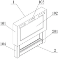
Fig. 1 is a schematic view of the overall structure of the present invention;
FIG. 2 is a schematic view of the internal structure of the grip of the present invention;
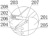
FIG. 3 is a schematic view of the structure at A of FIG. 2 according to the present invention;
fig. 4 is the utility model discloses well core rod's mounting structure schematic diagram.
In the figure: 1-armrest main body, 101-board plate, 102-advertisement groove, 103-hanging rope belt through groove, 104-connecting rod, 2-handle, 201-handle side edge, 202-center fixing block, 203-sliding side plate, 204-center rod, 205-first spring, 206-center sliding plate, 207-rotation connecting plate and 208-second spring.
Detailed Description
The technical solutions in the embodiments of the present invention will be described clearly and completely with reference to the accompanying drawings in the embodiments of the present invention, and it is obvious that the described embodiments are only some embodiments of the present invention, not all embodiments. Based on the embodiments in the present invention, all other embodiments obtained by a person skilled in the art without creative work belong to the protection scope of the present invention.
Referring to fig. 1-4, the present invention provides a technical solution:
the utility model provides a bus handrail convenient to grip, includes handrail body 1 and handle 2, the bottom of handrail body 1 is provided with handle 2, and this kind of setting realizes the fixed of user's arm through gripping to handle 2, handle 2 includes handle side 201, central fixed block 202, slip curb plate 203, well core rod 204, first spring 205, central slide 206, rotation connecting plate 207 and second spring 208, handle side 201 is symmetrical setting around being, is located both sides around being provided with central fixed block 202 between handle side 201, central fixed block 202 is setting up from top to bottom, the equal sliding connection has slip curb plate 203 in front end and the rear end inboard of central fixed block 202, and this kind of setting realizes being connected between 301 and the central fixed block 202 through slip curb plate 203, and makes handle side 201 can slide, slip curb plate 203 and handle side 201 fixed connection, the central rod 204 is fixedly connected between the central fixing blocks 202 positioned at the upper side and the lower side, the central rod 204 is fixed through the central fixing blocks 202, the outer end face of the central rod 204 is connected with a central sliding plate 206 in a sliding manner, the front end and the rear end of the central sliding plate 206 are both rotatably connected with a rotating connecting plate 207, the rotating connecting plate 207 is rotatably connected with the side edge 201 of the handle, the central sliding plate 206 and the side edge 201 of the handle are connected through the rotating connecting plate 207, and the handrail body 1 comprises a board plate 101, an advertisement groove 102, a hanging rope belt through groove 103 and a connecting rod 104.
The central fixing block 202 is fixedly connected with the connecting rod 104, the side edge 201 of the handle and the sliding side plate 203 are both connected with the connecting rod 104 in a sliding manner, and the central fixing block 202 is fixed through the connecting rod 104; the inner side of the top end of the board plate 101 is provided with a hanging rope belt through groove 103, the inner sides of the front end and the rear end of the board plate 101 are provided with advertisement grooves 102, the top end of the board plate 101 is fixedly connected with a connecting rod 104, the connecting rod 104 is arranged at the left end and the right end of the handle 2, the device can be fixed on a bus beam through a rope belt through the hanging rope belt through groove 103, and advertisements can be conveniently pasted through the advertisement grooves 102; the inner side of the central fixed block 202 is fixedly connected with a second spring 208, the other end of the second spring 208 is fixedly connected with the sliding side plate 203, and the arrangement facilitates driving the inner side of the central fixed block 202 of the sliding side plate 203 to pop up through accumulation of elastic potential energy of the second spring 208; the first spring 205 is arranged on the outer side of the central rod 204, and two ends of the first spring 205 are respectively and fixedly connected with the central sliding plates 206 positioned on the upper side and the lower side, so that elastic potential energy of the first spring 205 is accumulated, and the central sliding plates 206 are conveniently driven to enable the central sliding plates 206 to slide along the direction of the central rod 204; the central rods 204 are uniformly distributed on the inner side of the handle 2, the central rods 204 and the central fixing block 202 are arranged perpendicular to each other, the arrangement facilitates the sliding of the central sliding plate 206, and the central sliding plate 206 is always kept at the middle position of the handle side edges 201 on the front side and the rear side after sliding.
The working process is as follows: in the utility model, the device can be fixed on the bus beam through the rope belt by hanging the rope belt through the hanging rope belt through the groove 103, the advertisement can be conveniently pasted through the advertisement groove 102, when the device is used, the user can fix the arm of the user by holding the handle 2, the toppling of the user in the starting process of the bus is avoided, when part of women or underdeveloped users use the device, because the palm is smaller, the handle side edges 201 at the front and the back can be pressed relatively in the holding process of the handle 2, so that the handle side edges 201 are close to each other, the length of the outer peripheral surface of the handle 2 is reduced, the holding of the user with smaller palm is facilitated, after the handle side edges 201 are pressed, the handle side edges 201 can drive the sliding side plate 203 to slide into the inner side of the central fixed block 202, on one hand, the reduction of the top end and the bottom end surface of the handle 2 is realized, on the other hand, the second spring 208 is pressed, the elastic potential energy of the second spring 208 is accumulated, the sliding side plate 203 and the handle side 201 are conveniently driven to reset, the movement of the handle side 201 can also drive the central sliding plate 206 to move by rotating the connecting plate 207, the central sliding plate 206 slides along the direction of the central rod 204, the handle sides 201 on the front side and the rear side can simultaneously move in the sliding process, the movement distance is away from the box body, the phenomenon that the handle sides 201 on the front side and the rear side are staggered is avoided, the central sliding plate 206 can extrude the first spring 205 after sliding, the elastic potential energy of the first spring 205 is accumulated, the central sliding plate 206 is conveniently driven to reset the central sliding plate 206, and therefore the handle sides 201 reset when the handle sides 201 are not pressed.
Although embodiments of the present invention have been shown and described, it will be appreciated by those skilled in the art that changes, modifications, substitutions and alterations can be made in these embodiments without departing from the principles and spirit of the invention, the scope of which is defined in the appended claims and their equivalents.
Claims (6)
1. The utility model provides a bus handrail convenient to grip, includes handrail body (1) and handle (2), its characterized in that: the handle (2) is arranged at the bottom end of the handrail body (1), the handle (2) comprises handle side edges (201), a central fixing block (202), sliding side plates (203), a central rod (204), a first spring (205), a central sliding plate (206), a rotating connecting plate (207) and a second spring (208), the handle side edges (201) are symmetrically arranged in the front and back direction, the central fixing block (202) is arranged between the handle side edges (201) positioned at the front side and the back side, the central fixing block (202) is arranged up and down, the sliding side plates (203) are respectively connected to the inner sides of the front end and the back end of the central fixing block (202) in a sliding manner, the sliding side plates (203) are fixedly connected with the handle side edges (201), the central rod (204) is fixedly connected between the central fixing blocks (202) positioned at the upper side and the lower side, the outer end surface of the central rod (204) is connected with the central sliding plate (206) in a sliding manner, the front end and the rear end of the central sliding plate (206) are rotatably connected with a rotating connecting plate (207), the rotating connecting plate (207) is rotatably connected with the side edge (201) of the handle, and the handrail body (1) comprises a board plate (101), an advertisement groove (102), a hanging rope belt through groove (103) and a connecting rod (104).
2. A bus handrail convenient to hold as claimed in claim 1, wherein: the central fixing block (202) is fixedly connected with the connecting rod (104), and the grip side edge (201) and the sliding side plate (203) are both in sliding connection with the connecting rod (104).
3. A bus handrail convenient to hold as claimed in claim 1, wherein: the novel mahjong tile is characterized in that a hanging rope belt penetrating groove (103) is formed in the inner side of the top end of the board plate (101), advertisement grooves (102) are formed in the inner sides of the front end and the rear end of the board plate (101), a connecting rod (104) is fixedly connected to the top end of the board plate (101), and the connecting rod (104) is arranged at the left end and the right end of the handle (2).
4. A bus handrail convenient to hold as claimed in claim 1, wherein: the inner side of the central fixing block (202) is fixedly connected with a second spring (208), and the other end of the second spring (208) is fixedly connected with the sliding side plate (203).
5. A bus handrail convenient to hold as claimed in claim 1, wherein: the outer side of the central rod (204) is provided with a first spring (205), and two ends of the first spring (205) are respectively fixedly connected with a central sliding plate (206) positioned at the upper side and the lower side.
6. A bus handrail convenient to hold as claimed in claim 1, wherein: the center rod (204) is uniformly distributed on the inner side of the handle (2), and the center rod (204) and the center fixing block (202) are perpendicular to each other.
Priority Applications (1)
| Application Number | Priority Date | Filing Date | Title |
|---|---|---|---|
| CN202023289356.1U CN214267428U (en) | 2020-12-31 | 2020-12-31 | Bus handrail convenient to grip |
Applications Claiming Priority (1)
| Application Number | Priority Date | Filing Date | Title |
|---|---|---|---|
| CN202023289356.1U CN214267428U (en) | 2020-12-31 | 2020-12-31 | Bus handrail convenient to grip |
Publications (1)
| Publication Number | Publication Date |
|---|---|
| CN214267428U true CN214267428U (en) | 2021-09-24 |
Family
ID=77785912
Family Applications (1)
| Application Number | Title | Priority Date | Filing Date |
|---|---|---|---|
| CN202023289356.1U Active CN214267428U (en) | 2020-12-31 | 2020-12-31 | Bus handrail convenient to grip |
Country Status (1)
| Country | Link |
|---|---|
| CN (1) | CN214267428U (en) |
-
2020
- 2020-12-31 CN CN202023289356.1U patent/CN214267428U/en active Active
Similar Documents
| Publication | Publication Date | Title |
|---|---|---|
| CN210297090U (en) | Damage-proof adjustable power cable stripper | |
| CN209754781U (en) | Aluminum alloy window frame corner grinding device | |
| CN213259433U (en) | Hardware tool storage rack with adjusting function | |
| CN210710014U (en) | Small-size protective film sticky tape cutting machine structure | |
| CN215605422U (en) | Ground gap cleaning device | |
| CN217497761U (en) | Feeding device in steel processing equipment | |
| CN217924780U (en) | Personal safety device for exterior wall coating construction | |
| CN209110803U (en) | A kind of aluminium profile polishing machine | |
| CN212732793U (en) | Rolling type glass edge sealing auxiliary device with good edge sealing effect | |
| CN212944217U (en) | Wall brushing device special for self-cleaning of I-shaped steel joint | |
| CN210975682U (en) | Road surface cleaning device is used in municipal administration road bridge construction | |
| CN212638776U (en) | Feeding device before printing of hose bottle body | |
| CN213849242U (en) | An electric pickle jar cleaning brush | |
| CN205493722U (en) | Novel stair are clean device | |
| CN215940916U (en) | Hanger cleaning equipment for aluminum profile production | |
| CN216802910U (en) | Angle grinder for polishing rusted steel | |
| CN214107712U (en) | Elevator balancing weight roller coating device with good positioning effect | |
| CN217836452U (en) | Place stable antiskid type pottery emulsion bottle | |
| CN221537766U (en) | Forming machine for double-layer color steel | |
| CN215873761U (en) | Water-beating rod for makeup | |
| CN215205009U (en) | Material handling equipment that stability is good | |
| CN212123144U (en) | Stone breaking hammer with labor-saving structure for construction tool | |
| CN204580290U (en) | A kind of portable stretchable toothbrush | |
| CN213173506U (en) | Cleaning device for bridge pavement | |
| CN217268645U (en) | A whitewash device for interior decoration engineering |
Legal Events
| Date | Code | Title | Description |
|---|---|---|---|
| GR01 | Patent grant | ||
| GR01 | Patent grant |