CN214263566U - High-strength compound die of expansion water tank - Google Patents
High-strength compound die of expansion water tank Download PDFInfo
- Publication number
- CN214263566U CN214263566U CN202023264967.0U CN202023264967U CN214263566U CN 214263566 U CN214263566 U CN 214263566U CN 202023264967 U CN202023264967 U CN 202023264967U CN 214263566 U CN214263566 U CN 214263566U
- Authority
- CN
- China
- Prior art keywords
- die
- fixedly connected
- compound die
- expansion tank
- cushion block
- Prior art date
- Legal status (The legal status is an assumption and is not a legal conclusion. Google has not performed a legal analysis and makes no representation as to the accuracy of the status listed.)
- Active
Links
- 150000001875 compounds Chemical class 0.000 title claims abstract description 20
- XLYOFNOQVPJJNP-UHFFFAOYSA-N water Substances O XLYOFNOQVPJJNP-UHFFFAOYSA-N 0.000 title description 6
- 230000006835 compression Effects 0.000 claims abstract description 18
- 238000007906 compression Methods 0.000 claims abstract description 18
- 238000005520 cutting process Methods 0.000 claims abstract description 17
- 239000000758 substrate Substances 0.000 claims abstract description 8
- 238000004140 cleaning Methods 0.000 claims description 23
- 238000003825 pressing Methods 0.000 claims description 9
- 239000002131 composite material Substances 0.000 claims description 6
- 238000009966 trimming Methods 0.000 claims description 5
- 230000000149 penetrating effect Effects 0.000 claims description 3
- 229910000831 Steel Inorganic materials 0.000 abstract description 19
- 239000010959 steel Substances 0.000 abstract description 19
- 238000004519 manufacturing process Methods 0.000 abstract description 9
- 239000000463 material Substances 0.000 abstract description 5
- 238000004080 punching Methods 0.000 abstract description 2
- 238000000034 method Methods 0.000 description 6
- 230000009471 action Effects 0.000 description 3
- 230000008569 process Effects 0.000 description 3
- 230000004075 alteration Effects 0.000 description 1
- 230000009286 beneficial effect Effects 0.000 description 1
- 230000008901 benefit Effects 0.000 description 1
- 244000309464 bull Species 0.000 description 1
- 230000000694 effects Effects 0.000 description 1
- 239000007788 liquid Substances 0.000 description 1
- 239000002184 metal Substances 0.000 description 1
- 230000004048 modification Effects 0.000 description 1
- 238000012986 modification Methods 0.000 description 1
- 230000002035 prolonged effect Effects 0.000 description 1
- 125000003003 spiro group Chemical group 0.000 description 1
- 238000006467 substitution reaction Methods 0.000 description 1
Images


Landscapes
- Perforating, Stamping-Out Or Severing By Means Other Than Cutting (AREA)
Abstract
The utility model relates to a plate heat exchanger technical field just discloses an expansion tank's high strength compound die, including lower base, the compound die under the top fixedly connected with of base down, a plurality of fixed slots have been seted up at the top of compound die down, the top fixedly connected with of compound die is located the compression spring of diapire in the fixed slot down, compression spring's top fixed mounting has the gyro wheel. This expansion tank's high strength compound die, through placing the steel sheet at lower compound die, the top of gyro wheel and lower cushion, die mould hydraulic telescoping rod drive upper substrate downwardly moving, make upper die mould press the steel sheet to the compound die of lower compound die, carry out the die mould to the steel sheet and bend, through two cutting plates downward punching press steel sheets of side cut hydraulic telescoping rod drive and cut edge to the steel sheet, accomplish the die mould and cut edge the back, upper die mould breaks away from lower compound die along with upper substrate rebound, compression spring promotes the gyro wheel and then promotes the steel sheet and breaks away from lower compound die, the person of facilitating the use gets the material, the efficiency of production has been improved, and the time is saved.
Description
Technical Field
The utility model relates to a plate heat exchanger technical field specifically is an expansion tank's high strength compound die.
Background
The plate heat exchanger is an efficient heat exchanger formed by stacking a series of metal sheets with certain corrugated shapes, thin rectangular channels are formed among various plates, heat exchange is carried out through the plates, the plate heat exchanger is an ideal device for carrying out heat exchange on liquid-liquid or liquid-vapor, and the plate heat exchanger has the characteristics of high heat exchange efficiency, small heat loss, compact and light structure, small occupied area, wide application, long service life and the like.
An expansion tank is generally installed on a plate heat exchanger, so that water is prevented from being thermally expanded to affect normal operation of the heat exchanger, the expansion tank is generally made of steel plates, but when the expansion tank is produced at present, a die has an independent function, production efficiency is greatly affected, production time is prolonged, and the expansion tank is inconvenient to use, so that the high-strength composite die of the expansion tank is provided.
SUMMERY OF THE UTILITY MODEL
Technical problem to be solved
The utility model provides a not enough to prior art, the utility model provides an expansion tank's high strength compound die possesses die mould side cut integrative, conveniently gets the material, and advantage such as clean convenient have solved when present expansion tank produces, and the mould all is an solitary function, very influence production efficiency, has increased the time of production, the problem of inconvenient use.
(II) technical scheme
For realizing that above-mentioned die mould is cut edge integrative, conveniently get the material, clean convenient purpose, the utility model provides a following technical scheme: a high-strength compound die of an expansion water tank comprises a lower base, wherein the top of the lower base is fixedly connected with a lower die, the top of the lower die is provided with a plurality of fixing grooves, the top of the lower die is fixedly connected with a compression spring positioned on the inner bottom wall of the fixing grooves, the top end of the compression spring is fixedly provided with a roller, the top of the lower base is fixedly connected with two lower cushion blocks positioned on the left side and the right side of the lower die, the front side of each lower cushion block is provided with a fixing hole, the inside of each lower cushion block is fixedly connected with a cleaning stud positioned in the fixing hole through a bearing, the front end of the cleaning stud is fixedly connected with a rotating rod, the outer side of the cleaning stud is in threaded connection with a spiral ring, one side of the spiral ring, which is close to the lower die, is fixedly connected with a cleaning block penetrating through the lower cushion block, the four corners of the top of the lower base are fixedly connected with fixing seats, and the tops of the fixing seats are fixedly connected with positioning columns, the upper base plate is arranged above the lower base, positioning holes matched with the positioning columns are formed in four corners of the upper base plate, the profiling hydraulic telescopic rods are fixedly connected to the top of the upper base plate, an upper pressing die is fixedly connected to the bottom of the upper base plate, two strip holes which are located on the left side and the right side of the upper pressing die respectively are formed in the top of the upper base plate, a cutting plate is inserted into the top of each strip hole, and a trimming hydraulic telescopic rod is fixedly connected to the top of each cutting plate.
Preferably, the lower base and the upper substrate are the same in size, the left side and the right side of the lower die are tilted upwards, and the upper pressing die is matched with the lower die.
Preferably, the number of the fixing grooves is at least four and the fixing grooves are distributed in a square shape, and the normal height of the compression spring is equal to the depth of the fixing grooves.
Preferably, the roller is fixedly connected with the compression spring through a support, the top of the roller and the tops of the left end and the right end of the lower die are in the same level, and the fixing hole penetrates through one side, close to the lower die, of the lower cushion block.
Preferably, the distance between the lower cushion block and the lower die is matched with the width of the cutting plate, and the side of the cutting plate close to the upper die is at a thirty-degree tip.
Preferably, the size of the cleaning block is matched with the distance between the lower cushion block and the lower mold, and the bottom of the cleaning block is in contact with the lower base.
(III) advantageous effects
Compared with the prior art, the utility model provides an expansion tank's high strength compound die possesses following beneficial effect:
this expansion tank's high strength compound die, through placing the steel sheet at the lower mould clamping, the top of gyro wheel and lower cushion, die mould hydraulic telescoping rod drive upper substrate downwardly moving, make the upper die mould clamping down press the steel sheet, carry out the die mould to the steel sheet and bend, through two cutting plates of side cut hydraulic telescoping rod drive punching down steel sheet and cut edge to the steel sheet, accomplish the die mould and cut edge the back, the upper die breaks away from the lower mould clamping along with upper substrate rebound, compression spring promotes the gyro wheel and then promotes the steel sheet and breaks away from the lower mould clamping, the person of facilitating the use gets the material, the efficiency of production has been improved, save time, utilize the bull stick to rotate clean double-screw bolt and drive the spiral ring and remove, can drive the debris between clean piece and will lower mould clamping and release, convenient clearance.
Drawings
FIG. 1 is a schematic structural view of the present invention;
FIG. 2 is an enlarged schematic view of the structure at the position A of the present invention;
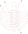
fig. 3 is an enlarged schematic view of the structure at the position B of the present invention.
In the figure: 1. a lower base; 2. lower die assembly; 3. fixing grooves; 4. a compression spring; 5. a roller; 6. a lower cushion block; 7. a fixing hole; 8. cleaning the stud; 9. a rotating rod; 10. a spiro ring; 11. a cleaning block; 12. a fixed seat; 13. a positioning column; 14. an upper substrate; 15. positioning holes; 16. profiling hydraulic telescopic rods; 17. pressing the die; 18. a bar hole; 19. cutting a plate; 20. and (5) trimming hydraulic telescopic rods.
Detailed Description
The technical solutions in the embodiments of the present invention will be described clearly and completely with reference to the accompanying drawings in the embodiments of the present invention, and it is obvious that the described embodiments are only some embodiments of the present invention, not all embodiments. Based on the embodiments in the present invention, all other embodiments obtained by a person skilled in the art without creative work belong to the protection scope of the present invention.
Referring to fig. 1-3, a high-strength compound die of an expansion water tank comprises a lower base 1, a lower die 2 is fixedly connected to the top of the lower base 1, a plurality of fixing grooves 3 are formed in the top of the lower die 2, compression springs 4 located on the inner bottom walls of the fixing grooves 3 are fixedly connected to the top of the lower die 2, rollers 5 are fixedly mounted at the top ends of the compression springs 4, the number of the fixing grooves 3 is at least four and the fixing grooves are distributed in a square shape, the normal height of each compression spring 4 is equal to the depth of each fixing groove 3, two lower cushion blocks 6 located on the left side and the right side of the lower die 2 are fixedly connected to the top of the lower base 1, fixing holes 7 are formed in the front surfaces of the lower cushion blocks 6, cleaning studs 8 located in the fixing holes 7 are fixedly connected to the inside of each lower cushion block 6 through a bearing, the rollers 5 are fixedly connected to the compression springs 4 through a support, the tops of the rollers 5 are at the same level with the tops of the left end and the right end of the lower die 2, the fixed hole 7 penetrates through one side of the lower cushion block 6 close to the lower die 2, the front end of the cleaning stud 8 is fixedly connected with a rotating rod 9, the outer side of the cleaning stud 8 is in threaded connection with a spiral ring 10, one side of the spiral ring 10 close to the lower die 2 is fixedly connected with a cleaning block 11 penetrating through the lower cushion block 6, the size of the cleaning block 11 is matched with the distance between the lower cushion block 6 and the lower die 2, the bottom of the cleaning block 11 is in contact with the lower base 1, four corners of the top of the lower base 1 are fixedly connected with fixed seats 12, the top of the fixed seats 12 is fixedly connected with a positioning column 13, an upper base plate 14 is arranged above the lower base 1, the sizes of the lower base 1 and the upper base plate 14 are the same, four corners of the upper base plate 14 are respectively provided with positioning holes 15 matched with the positioning columns 13, the top of the upper base plate 14 is fixedly connected with a profiling hydraulic telescopic rod 16, the bottom of the upper base plate 14 is fixedly connected with an upper pressing die 17, the distance between the lower cushion block 6 and the lower die 2 is matched with the width of the cutting plate 19, one side that cutting plate 19 is close to last moulding-die 17 is thirty degrees most advanced, and the left and right sides that closes mould 2 makes progress the perk down, goes up moulding-die 17 and closes mould 2 phase-match down, and two strip holes 18 that are located the last moulding-die 17 left and right sides respectively are seted up to the top of upper substrate 14, and the top in strip hole 18 is pegged graft there is cutting plate 19, and the top fixedly connected with side cut hydraulic telescoping rod 20 of cutting plate 19.
In conclusion, according to the high-strength compound die of the expansion water tank, a steel plate is placed on the tops of the lower die 2, the roller 5 and the lower cushion block 6, the profiling hydraulic telescopic rod 16 drives the upper base plate 14 to move downwards, so that the upper die 17 presses the steel plate towards the lower die 2, the steel plate is profiled and bent, the trimming hydraulic telescopic rod 20 drives the two cutting plates 19 to punch the steel plate downwards and trim the steel plate, after the profiling trimming is completed, the upper die 17 moves upwards along with the upper base plate 14 to be separated from the lower die 2, the compression spring 4 pushes the roller 5 to push the steel plate to be separated from the lower die 2, a user can take materials conveniently, the production efficiency is improved, the time is saved, the rotating rod 9 is used for rotating the cleaning stud 8 to drive the spiral ring 10 to move, the cleaning block 11 can be driven to push out sundries between the lower die 2 and the lower cushion block 6, the cleaning is convenient, the mould is an independent function, influences production efficiency very much, has increased the time of production, inconvenient problem of using.
It is noted that, herein, relational terms such as first and second, and the like may be used solely to distinguish one entity or action from another entity or action without necessarily requiring or implying any actual such relationship or order between such entities or actions. Also, the terms "comprises," "comprising," or any other variation thereof, are intended to cover a non-exclusive inclusion, such that a process, method, article, or apparatus that comprises a list of elements does not include only those elements but may include other elements not expressly listed or inherent to such process, method, article, or apparatus. Without further limitation, an element defined by the phrase "comprising an … …" does not exclude the presence of other identical elements in a process, method, article, or apparatus that comprises the element.
Although embodiments of the present invention have been shown and described, it will be appreciated by those skilled in the art that changes, modifications, substitutions and alterations can be made in these embodiments without departing from the principles and spirit of the invention, the scope of which is defined in the appended claims and their equivalents.
Claims (6)
1. The utility model provides an expansion tank's high strength compound die, includes lower base (1), its characterized in that: the top of the lower base (1) is fixedly connected with a lower die (2), the top of the lower die (2) is provided with a plurality of fixing grooves (3), the top of the lower die (2) is fixedly connected with compression springs (4) positioned on the inner bottom walls of the fixing grooves (3), the top ends of the compression springs (4) are fixedly provided with rollers (5), the top of the lower base (1) is fixedly connected with two lower cushion blocks (6) positioned on the left side and the right side of the lower die (2), the front of each lower cushion block (6) is provided with a fixing hole (7), the inner part of each lower cushion block (6) is fixedly connected with a cleaning stud (8) positioned in the fixing hole (7) through a bearing, the front end of each cleaning stud (8) is fixedly connected with a rotating rod (9), the outer side of each cleaning stud (8) is in threaded connection with a spiral ring (10), one side of each spiral ring (10) close to the lower die (2) is fixedly connected with a cleaning block (11) penetrating through the lower cushion block (6), the improved structure of the hydraulic telescopic cutting die is characterized in that fixing seats (12) are fixedly connected to four corners of the top of the lower base (1), positioning columns (13) are fixedly connected to the top of the fixing seats (12), an upper base plate (14) is arranged above the lower base (1), positioning holes (15) matched with the positioning columns (13) are formed in the four corners of the upper base plate (14), profiling hydraulic telescopic rods (16) are fixedly connected to the top of the upper base plate (14), an upper pressing die (17) is fixedly connected to the bottom of the upper base plate (14), two strip holes (18) which are located on the left side and the right side of the upper pressing die (17) are formed in the top of the upper base plate (14), cutting plates (19) are inserted into the tops of the strip holes (18), and trimming hydraulic telescopic rods (20) are fixedly connected to the tops of the cutting plates (19).
2. The high-strength composite die for the expansion tank as claimed in claim 1, wherein: the size of the lower base (1) is the same as that of the upper substrate (14), the left side and the right side of the lower die assembly (2) are tilted upwards, and the upper pressing die (17) is matched with the lower die assembly (2).
3. The high-strength composite die for the expansion tank as claimed in claim 1, wherein: the number of fixed slot (3) is four at least and be square distribution, the normal height of compression spring (4) equals with the degree of depth of fixed slot (3).
4. The high-strength composite die for the expansion tank as claimed in claim 1, wherein: the roller (5) is fixedly connected with the compression spring (4) through a support, the top of the roller (5) and the tops of the left end and the right end of the lower die assembly (2) are in the same level, and the fixing hole (7) penetrates through the lower cushion block (6) and is close to one side of the lower die assembly (2).
5. The high-strength composite die for the expansion tank as claimed in claim 1, wherein: the distance between the lower cushion block (6) and the lower die closing (2) is matched with the width of the cutting plate (19), and one side of the cutting plate (19) close to the upper pressing die (17) is at a thirty-degree tip.
6. The high-strength composite die for the expansion tank as claimed in claim 1, wherein: the size of the cleaning block (11) is matched with the distance between the lower cushion block (6) and the lower mold closing (2), and the bottom of the cleaning block (11) is contacted with the lower base (1).
Priority Applications (1)
| Application Number | Priority Date | Filing Date | Title |
|---|---|---|---|
| CN202023264967.0U CN214263566U (en) | 2020-12-30 | 2020-12-30 | High-strength compound die of expansion water tank |
Applications Claiming Priority (1)
| Application Number | Priority Date | Filing Date | Title |
|---|---|---|---|
| CN202023264967.0U CN214263566U (en) | 2020-12-30 | 2020-12-30 | High-strength compound die of expansion water tank |
Publications (1)
| Publication Number | Publication Date |
|---|---|
| CN214263566U true CN214263566U (en) | 2021-09-24 |
Family
ID=77785453
Family Applications (1)
| Application Number | Title | Priority Date | Filing Date |
|---|---|---|---|
| CN202023264967.0U Active CN214263566U (en) | 2020-12-30 | 2020-12-30 | High-strength compound die of expansion water tank |
Country Status (1)
| Country | Link |
|---|---|
| CN (1) | CN214263566U (en) |
-
2020
- 2020-12-30 CN CN202023264967.0U patent/CN214263566U/en active Active
Similar Documents
| Publication | Publication Date | Title |
|---|---|---|
| CN103223436B (en) | Shrapnel die trimming device of assembly machine with shrapnel being automatically mounted on cap | |
| CN210497770U (en) | Metal stamping die side-cut structure | |
| CN212469734U (en) | Die casting side cut mould | |
| CN209773245U (en) | Side pushes away slider forming structure | |
| CN111604994A (en) | High-precision die cutting machine and die cutting method for honeycomb paperboard | |
| CN217070339U (en) | Stamping forming integration mould | |
| CN214321478U (en) | Numerical control punch press is used in perforated plate production | |
| CN222790426U (en) | Hook punching machine | |
| CN216150812U (en) | Middle plate small hole punching device | |
| CN117718382B (en) | A door sill middle section forming mold and forming method thereof | |
| CN221493835U (en) | Self-cleaning computer cooling fin stamping device | |
| CN210647954U (en) | Case backplate punching press subassembly | |
| CN211101125U (en) | Punch forming module of box shell die | |
| CN210702008U (en) | Radiator main fin cut-out press | |
| CN107521142B (en) | A kind of Sheet Metal Forming Technology | |
| CN218168375U (en) | Multi-layer multi-region cold punching die | |
| CN221912339U (en) | Aluminum foil punching machine | |
| CN220445202U (en) | Steel plate shearing device | |
| CN212397805U (en) | Novel sheet metal punching device | |
| CN214686918U (en) | Spare tire cover folded and traceless eager cutting device | |
| CN210475357U (en) | Novel split heads production facility | |
| CN218804227U (en) | Waste material device is cut to cylinder type | |
| CN213613643U (en) | A composite die for trimming and punching for automotive sheet metal stamping parts | |
| CN220092844U (en) | Blanking die convenient for material taking | |
| CN222343937U (en) | Multichannel cutting die |
Legal Events
| Date | Code | Title | Description |
|---|---|---|---|
| GR01 | Patent grant | ||
| GR01 | Patent grant |