CN214253522U - High school mathematics plane geometry teaching board - Google Patents
High school mathematics plane geometry teaching board Download PDFInfo
- Publication number
- CN214253522U CN214253522U CN202022573989.9U CN202022573989U CN214253522U CN 214253522 U CN214253522 U CN 214253522U CN 202022573989 U CN202022573989 U CN 202022573989U CN 214253522 U CN214253522 U CN 214253522U
- Authority
- CN
- China
- Prior art keywords
- fixed
- plate body
- teaching board
- auxiliary rod
- blocks
- Prior art date
- Legal status (The legal status is an assumption and is not a legal conclusion. Google has not performed a legal analysis and makes no representation as to the accuracy of the status listed.)
- Expired - Fee Related
Links
- 238000000034 method Methods 0.000 description 5
- 238000001125 extrusion Methods 0.000 description 2
- 230000004048 modification Effects 0.000 description 2
- 238000012986 modification Methods 0.000 description 2
- 230000009286 beneficial effect Effects 0.000 description 1
- 238000004891 communication Methods 0.000 description 1
- 238000010276 construction Methods 0.000 description 1
- 230000000694 effects Effects 0.000 description 1
- 239000007787 solid Substances 0.000 description 1
Images



Landscapes
- Purses, Travelling Bags, Baskets, Or Suitcases (AREA)
Abstract
The application discloses a high school mathematics plane geometry teaching board, which comprises a board body, a rotating structure and an auxiliary structure, wherein the middle positions of two sides of the board body are rotatably connected with a supporting frame; the rotating structure comprises fixed blocks and two moving rods, wherein the moving rods penetrate through the supporting frames, and the fixed blocks are fixed on the moving rods. Through the carriage release lever, spring and stopper cooperation, can rotate the plate body after spacing fixed, thereby it is more convenient to make the plate body rotate when using, the comparatively inconvenient problem of current teaching board rotation when using has been solved, the convenience when having improved the teaching board and using, assist through sharp auxiliary rod, make things convenient for the mr to carry out sharp drawing when the lecture, and through deflector and spout cooperation, guarantee that sharp auxiliary rod is in the level all the time and place, and can fix sharp auxiliary rod at the plate body side through the rubber piece, thereby avoid sharp auxiliary rod to influence the normal use of plate body, the practicality of plate body has been improved.
Description
Technical Field
The application relates to a teaching board, in particular to a high school mathematics plane geometry teaching board.
Background
The content of high school mathematics study is more extensive, like plane geometry, solid geometry and function etc. when the teacher explains, need draw and assist, for the convenience of teacher's explanation on the current teaching board, is provided with coordinate line and bevel protractor at the plate body rear side.
Teaching board when needs are drawn, because be fixed connection between current teaching board and the support frame, need wholly rotate the teaching board, because teaching board and support frame all have certain weight, comparatively hard when rotating, the convenient rotation of pulley is passed through to some support frame bottom, but its rotation is accomplished the back, and is fixed comparatively inconvenient, the convenience when reducing the teaching board and using.
But still need carry out the straight line drawing according to actual conditions when the mr is drawing, and do not set up the straight line on the current teaching board and draw auxiliary structure, lead to the mr to need with the help of outside instrument drawing, reduced the practicality of teaching board. Therefore, a high school mathematics plane geometry teaching board is proposed to address the above problems.
Disclosure of Invention
The high school mathematics plane geometry teaching board comprises a board body, a rotating structure and an auxiliary structure, wherein the middle positions of two sides of the board body are rotatably connected with a supporting frame;
the rotating structure comprises fixed blocks, moving rods penetrate through the two support frames, the moving rods are fixed on the fixed blocks, springs are sleeved on the moving rods on the inner sides of the fixed blocks, one ends of the springs are fixed on the fixed blocks, moving blocks are sleeved on the moving rods on the other ends of the springs, the other ends of the springs are fixed on the moving blocks, fixed grooves matched with the moving rods are formed in the upper ends and the lower ends of the plate bodies, limiting blocks are fixed on the moving rods on the outer sides of the fixed blocks, limiting grooves matched with the limiting blocks are formed in the support frames, and movable cavities matched with the fixed blocks and the moving blocks are formed in the support frames;
the auxiliary structure comprises a linear auxiliary rod, the rear side of the plate body is clamped with the linear auxiliary rod, two sides of the linear auxiliary rod are connected with guide plates in a sliding mode through sliding grooves, the guide plates are all fixed on the plate body, and rubber blocks are glued to the upper end and the lower end of one side, opposite to the guide plates.
Further, plate body front side top and rear side bottom all are fixed with the handle, the one end that the carriage release lever extends to the plate body outside all sets up to the arc.
Furthermore, the fixed block, the moving block and the movable cavity are all set to be circular and matched with each other, and the top ends of the limiting blocks are all set to be arc-shaped.
Furthermore, the limiting grooves are all arranged in an L shape, and the length of the limiting grooves is larger than that of the fixing grooves.
Furthermore, arc-shaped grooves are symmetrically formed in the middle of the linear auxiliary rod, and the length between the two guide plates is smaller than that of the linear auxiliary rod.
Further, the rubber blocks are all set to be arc-shaped, and the thickness of each rubber block is larger than the thickness from the sliding groove to the guide plate.
The beneficial effect of this application is: the application provides a high school mathematics plane geometry teaching board.
Drawings
In order to more clearly illustrate the embodiments of the present application or the technical solutions in the prior art, the drawings needed to be used in the description of the embodiments or the prior art will be briefly introduced below, and it is obvious that the drawings in the following description are only some embodiments of the present application, and it is obvious for those skilled in the art that other drawings can be obtained according to the drawings without inventive exercise.
FIG. 1 is a schematic cross-sectional elevation view of an embodiment of the present application;
FIG. 2 is a schematic structural rear view of an embodiment of the present application;
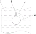
FIG. 3 is a schematic top view cross-section of a portion of an embodiment of the present application;
FIG. 4 is a schematic side cross-sectional view of a portion of one embodiment of the present application;
FIG. 5 is a schematic cross-sectional side view of a partial structure of an embodiment of the present application;
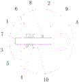
fig. 6 is an enlarged schematic view of a structure at a in fig. 1 according to an embodiment of the present application.
In the figure: 1. plate body, 2, support frame, 3, carriage release lever, 4, fixed block, 5, movable block, 6, spring, 7, fixed slot, 8, stopper, 9, spacing groove, 10, activity chamber, 11, handle, 12, sharp auxiliary rod, 13, deflector, 14, spout, 15, block rubber.
Detailed Description
In order to make the technical solutions better understood by those skilled in the art, the technical solutions in the embodiments of the present application will be clearly and completely described below with reference to the drawings in the embodiments of the present application, and it is obvious that the described embodiments are only partial embodiments of the present application, but not all embodiments. All other embodiments, which can be derived by a person skilled in the art from the embodiments given herein without making any creative effort, shall fall within the protection scope of the present application.
It should be noted that the terms "first," "second," and the like in the description and claims of this application and in the drawings described above are used for distinguishing between similar elements and not necessarily for describing a particular sequential or chronological order. It should be understood that the data so used may be interchanged under appropriate circumstances such that embodiments of the application described herein may be used. Furthermore, the terms "comprises," "comprising," and "having," and any variations thereof, are intended to cover a non-exclusive inclusion, such that a process, method, system, article, or apparatus that comprises a list of steps or elements is not necessarily limited to those steps or elements expressly listed, but may include other steps or elements not expressly listed or inherent to such process, method, article, or apparatus.
In this application, the terms "upper", "lower", "left", "right", "front", "rear", "top", "bottom", "inner", "outer", "middle", "vertical", "horizontal", "lateral", "longitudinal", and the like indicate orientations or positional relationships based on the orientations or positional relationships shown in the drawings. These terms are used primarily to better describe the present application and its embodiments, and are not used to limit the indicated devices, elements or components to a particular orientation or to be constructed and operated in a particular orientation.
Moreover, some of the above terms may be used to indicate other meanings besides the orientation or positional relationship, for example, the term "on" may also be used to indicate some kind of attachment or connection relationship in some cases. The specific meaning of these terms in this application will be understood by those of ordinary skill in the art as appropriate.
Furthermore, the terms "mounted," "disposed," "provided," "connected," and "sleeved" are to be construed broadly. For example, it may be a fixed connection, a removable connection, or a unitary construction; can be a mechanical connection, or an electrical connection; may be directly connected, or indirectly connected through intervening media, or may be in internal communication between two devices, elements or components. The specific meaning of the above terms in the present application can be understood by those of ordinary skill in the art as appropriate.
It should be noted that the embodiments and features of the embodiments in the present application may be combined with each other without conflict. The present application will be described in detail below with reference to the embodiments with reference to the attached drawings.
Referring to fig. 1-6, the teaching board for high school mathematics plane geometry comprises a board body 1, a rotating structure and an auxiliary structure, wherein a supporting frame 2 is rotatably connected to the middle position of two sides of the board body 1;
the rotating structure comprises fixed blocks 4, moving rods 3 penetrate through two support frames 2, the moving rods 3 are fixed with the fixed blocks 4, springs 6 are sleeved on the moving rods 3 on the inner sides of the fixed blocks 4, one ends of the springs 6 are fixed on the fixed blocks 4, moving blocks 5 are sleeved on the moving rods 3 on the other ends of the springs 6, the other ends of the springs 6 are fixed on the moving blocks 5, fixing grooves 7 matched with the moving rods 3 are formed in the upper end and the lower end of a plate body 1, limiting blocks 8 are fixed on the moving rods 3 on the outer sides of the fixed blocks 4, limiting grooves 9 matched with the limiting blocks 8 are formed in the support frames 2, and movable cavities 10 matched with the fixed blocks 4 and the moving blocks 5 are formed in the support frames 2;
the auxiliary structure comprises a linear auxiliary rod 12, the rear side of the plate body 1 is clamped with the linear auxiliary rod 12, two sides of the linear auxiliary rod 12 are connected with guide plates 13 in a sliding mode through sliding grooves 14, the guide plates 13 are fixed on the plate body 1, and rubber blocks 15 are glued to the upper end and the lower end of one side, opposite to the guide plates 13, of each guide plate 13.
The handles 11 are fixed at the top end of the front side and the bottom end of the rear side of the plate body 1, and the ends of the movable rods 3 extending to the outer side of the plate body 1 are all arc-shaped; the fixed block 4, the moving block 5 and the movable cavity 10 are all arranged into mutually matched circles, and the top ends of the limiting blocks 8 are all arranged into arcs; the limiting grooves 9 are all arranged in an L shape, and the length of the limiting grooves 9 is larger than that of the fixing grooves 7; arc-shaped grooves are symmetrically formed in the middle of the linear auxiliary rod 12, and the length between the two guide plates 13 is smaller than that of the linear auxiliary rod 12; the rubber blocks 15 are all arranged in an arc shape, and the thickness of each rubber block 15 is larger than the thickness between the sliding chute 14 and the guide plate 13.
When the plate body drawing device is used, when drawing is needed through the back of the plate body 1, the moving rods 3 on two sides are respectively rotated to drive the limiting blocks 8 to rotate to the limiting grooves 9 and the transverse sections, the moving rods 3 are loosened to enable the moving rods 3 to move outwards under the pushing of the springs 6, meanwhile, the limiting blocks 8 are driven to slide in the limiting grooves 9, at the moment, the moving rods 3 move out of the fixing grooves 7, the fixing of the plate body 1 can be released, the plate body 1 is pulled through the handle 11, after the plate body 1 rotates and turns over under the supporting matching of the supporting frame 2, the moving rods 3 are pushed to enable the moving rods 3 to be inserted into the other fixing grooves 7, then the moving rods 3 are rotated to enable the moving rods 3 to drive the limiting blocks 8 to rotate to the vertical sections of the limiting grooves 9, the plate body can be limited and fixed through the limiting grooves 9, when linear drawing is needed, the linear auxiliary rods 12 are pulled through the arc-shaped grooves, so that the linear auxiliary rods 12 slide up and down under the matching of the guide plates 13, after sharp auxiliary rod 12 slided to misplacing with block rubber 15, block rubber 15 relieved the spacing of block rubber 12, can assist the marking off through sharp auxiliary rod 12, after the completion of marking off of sharp auxiliary rod 12, with sharp auxiliary rod 12 pulling to plate body 1 top or bottom to make sharp auxiliary rod 12 both ends extrusion block rubber 15, thereby the extrusion force through block rubber 15 is fixed with sharp auxiliary rod 12.
The application has the advantages that:
1. the utility model has simple structure and convenient operation, and can limit and fix the plate body 1 after rotating through the matching of the moving rod 3, the spring 6 and the limiting block 8, thereby leading the plate body 1 to rotate more conveniently when in use, solving the problem that the prior teaching board rotates more inconveniently when in use, and improving the convenience when in use;
2. this application is rational in infrastructure, assists through sharp auxiliary rod 12, makes things convenient for the mr to carry out sharp drawing when the lecture, and through deflector 13 and the cooperation of spout 14, guarantees that sharp auxiliary rod 12 is in the level all the time and places, and can fix sharp auxiliary rod 12 at plate body 1 side through block rubber 15 to avoid sharp auxiliary rod 12 to influence the normal use of plate body 1, improved plate body 1's practicality.
It is well within the skill of those in the art to implement, without undue experimentation, the present application is not directed to software and process improvements, as they relate to circuits and electronic components and modules.
The above description is only a preferred embodiment of the present application and is not intended to limit the present application, and various modifications and changes may be made by those skilled in the art. Any modification, equivalent replacement, improvement and the like made within the spirit and principle of the present application shall be included in the protection scope of the present application.
Claims (6)
1. High school mathematics plane geometry teaching board, its characterized in that: the novel board comprises a board body (1), a rotating structure and an auxiliary structure, wherein a support frame (2) is rotatably connected to the middle positions of two sides of the board body (1);
the rotating structure comprises fixed blocks (4), moving rods (3) penetrate through the two supporting frames (2), the movable rods (3) are all fixed with fixed blocks (4), the movable rods (3) at the inner sides of the fixed blocks (4) are all sleeved with springs (6), one end of a spring (6) is fixed on the fixed block (4), moving blocks (5) are sleeved on the moving rods (3) at the other end of the spring (6), the other end of the spring (6) is fixed on the movable block (5), the upper end and the lower end of the plate body (1) are provided with fixed grooves (7) matched with the movable rod (3), a limiting block (8) is fixed on the moving rod (3) at the outer side of the fixed block (4), the supporting frame (2) is internally provided with a limit groove (9) matched with the limit block (8), a movable cavity (10) matched with the fixed block (4) and the moving block (5) is formed in the support frame (2);
the auxiliary structure comprises a linear auxiliary rod (12), the rear side of the plate body (1) is clamped with the linear auxiliary rod (12), two sides of the linear auxiliary rod (12) are connected with guide plates (13) in a sliding mode through sliding grooves (14), the guide plates (13) are all fixed on the plate body (1), and rubber blocks (15) are glued to the upper end and the lower end of one side, opposite to the guide plates (13).
2. The high school mathematics plane geometry teaching board of claim 1, wherein: plate body (1) front side top and rear side bottom all are fixed with handle (11), the one end that carriage release lever (3) extended to the plate body (1) outside all sets up to the arc.
3. The high school mathematics plane geometry teaching board of claim 1, wherein: the fixed block (4), the moving block (5) and the movable cavity (10) are all set to be circular and matched with each other, and the top ends of the limiting blocks (8) are all set to be arc-shaped.
4. The high school mathematics plane geometry teaching board of claim 1, wherein: the limiting grooves (9) are L-shaped, and the length of the limiting grooves (9) is larger than that of the fixing grooves (7).
5. The high school mathematics plane geometry teaching board of claim 1, wherein: arc-shaped grooves are symmetrically formed in the middle of the linear auxiliary rod (12), and the length between the two guide plates (13) is smaller than that of the linear auxiliary rod (12).
6. The high school mathematics plane geometry teaching board of claim 1, wherein: the rubber blocks (15) are all arranged in an arc shape, and the thickness of each rubber block (15) is larger than the thickness between the sliding groove (14) and the guide plate (13).
Priority Applications (1)
| Application Number | Priority Date | Filing Date | Title |
|---|---|---|---|
| CN202022573989.9U CN214253522U (en) | 2020-11-09 | 2020-11-09 | High school mathematics plane geometry teaching board |
Applications Claiming Priority (1)
| Application Number | Priority Date | Filing Date | Title |
|---|---|---|---|
| CN202022573989.9U CN214253522U (en) | 2020-11-09 | 2020-11-09 | High school mathematics plane geometry teaching board |
Publications (1)
| Publication Number | Publication Date |
|---|---|
| CN214253522U true CN214253522U (en) | 2021-09-21 |
Family
ID=77731739
Family Applications (1)
| Application Number | Title | Priority Date | Filing Date |
|---|---|---|---|
| CN202022573989.9U Expired - Fee Related CN214253522U (en) | 2020-11-09 | 2020-11-09 | High school mathematics plane geometry teaching board |
Country Status (1)
| Country | Link |
|---|---|
| CN (1) | CN214253522U (en) |
Cited By (1)
| Publication number | Priority date | Publication date | Assignee | Title |
|---|---|---|---|---|
| CN115072607A (en) * | 2022-06-30 | 2022-09-20 | 扬州市伏尔坎机械制造有限公司 | Make things convenient for hoisting device for wind power equipment transportation of centre gripping |
-
2020
- 2020-11-09 CN CN202022573989.9U patent/CN214253522U/en not_active Expired - Fee Related
Cited By (1)
| Publication number | Priority date | Publication date | Assignee | Title |
|---|---|---|---|---|
| CN115072607A (en) * | 2022-06-30 | 2022-09-20 | 扬州市伏尔坎机械制造有限公司 | Make things convenient for hoisting device for wind power equipment transportation of centre gripping |
Similar Documents
| Publication | Publication Date | Title |
|---|---|---|
| CN110338562A (en) | A kind of multifunctional artistic design drawing device | |
| CN107443965A (en) | A kind of English teaching board | |
| CN201761229U (en) | Multi-function line drawer | |
| CN202242612U (en) | Four-line three-cell scribing device for English teaching | |
| CN209552826U (en) | A kind of fine arts drawing boards height adjustment device | |
| CN209869862U (en) | Multipurpose die for mathematical drawing | |
| CN207867749U (en) | A kind of novel Chinese literature comparison learning device | |
| CN203888477U (en) | Simple mark scraper for English four-line grid | |
| CN218004248U (en) | a teaching aid | |
| CN211390755U (en) | English scriber | |
| CN213441816U (en) | Object moving curve demonstration device for mathematical education | |
| CN203511082U (en) | Scriber for English teaching | |
| CN202378564U (en) | Mathematics teaching tool | |
| CN208881439U (en) | A kind of Higher Mathematics Teaching drawing board | |
| CN211335310U (en) | Blackboard convenient for drawing lines | |
| CN204360656U (en) | Economical management teaching plotting sheet | |
| CN218138020U (en) | A marking device for BIM steel parts | |
| CN215126261U (en) | A pinyin explanation device for primary school Chinese classrooms | |
| CN201506159U (en) | Parallel line drawing tool | |
| CN206633663U (en) | A kind of space multistory figure drawing instrument for being easy to Higher Mathematics Teaching | |
| CN210983907U (en) | Portable colleges and universities are teaching aid for english teaching | |
| CN218702400U (en) | Multifunctional mathematical drawing tool | |
| CN220808978U (en) | Curve drawing device | |
| CN220242866U (en) | Mathematical drawing device | |
| CN211730825U (en) | Teaching tool of convenient transportation |
Legal Events
| Date | Code | Title | Description |
|---|---|---|---|
| GR01 | Patent grant | ||
| GR01 | Patent grant | ||
| CF01 | Termination of patent right due to non-payment of annual fee | ||
| CF01 | Termination of patent right due to non-payment of annual fee |
Granted publication date: 20210921 |