CN214244653U - Automobile electrophoresis energy-saving device - Google Patents
Automobile electrophoresis energy-saving device Download PDFInfo
- Publication number
- CN214244653U CN214244653U CN202120225084.4U CN202120225084U CN214244653U CN 214244653 U CN214244653 U CN 214244653U CN 202120225084 U CN202120225084 U CN 202120225084U CN 214244653 U CN214244653 U CN 214244653U
- Authority
- CN
- China
- Prior art keywords
- pipeline
- tank
- degreasing
- degreasing tank
- flood
- Prior art date
- Legal status (The legal status is an assumption and is not a legal conclusion. Google has not performed a legal analysis and makes no representation as to the accuracy of the status listed.)
- Active
Links
Images
Landscapes
- Electrostatic Separation (AREA)
Abstract
The utility model discloses an automobile electrophoresis energy-saving device, which comprises a first degreasing tank, a second degreasing tank and a flood washing tank which are connected in sequence through pipelines; the device is characterized by further comprising a degreasing tank, wherein a liquid outlet of the flood flushing tank is communicated with a liquid inlet of the degreasing tank through a pipeline, the liquid outlet of the degreasing tank is communicated with a liquid inlet of the flood discharging tank through a pipeline, and a control valve is arranged on the pipeline. The utility model discloses a newly-increased degreasing is equipped with the groove, flows the groove liquor in the flood flow groove to being equipped with the groove, deposits through being equipped with the groove and reduces the groove liquor and discharge, reaches energy saving and emission reduction's effect.
Description
Technical Field
The utility model belongs to the technical field of the electrophoresis application technique and specifically relates to an automobile electrophoresis economizer is related to.
Background
The existing automobile part electrophoretic coating production equipment mainly comprises a workpiece conveying device, a driving device, a degreasing device, a phosphating device and an electrophoresis device, wherein the workpiece conveying device sequentially conveys automobile parts to the degreasing device for degreasing, the phosphating device for phosphating and the electrophoresis device for electrophoresis through the driving device so as to finish the electrophoretic coating of the automobile parts, enhance the corrosion resistance and the rust resistance of the automobile parts and ensure the service life of the automobile. In the processing and manufacturing of the automobile body, the electrophoresis of the automobile body is an important step, and the electrophoresis of the automobile body is also an important protection means, so that the service life of the automobile body can be greatly prolonged, and the long-term use reliability of the automobile body is ensured.
In the automobile pretreatment electrophoresis process, in order to maintain the stability of bath solution, ensure the degreasing and scrap iron capacity of pretreatment and improve the quality of an electrophoretic paint film, the bath body and joint equipment need to be cleaned regularly, the bath solution needs to be updated, and a groove inversion process needs to be carried out; therefore, not only is the time of the working personnel wasted, but also the production efficiency is not high.
SUMMERY OF THE UTILITY MODEL
The to-be-solved technical problem of the utility model is: overcome prior art's not enough, provide one kind and deposit, filter and cyclic utilization's the liquid in the flood flushing tank device, wash the work piece with filterable liquid again, prevent to cause the waste of water resource.
The utility model provides a technical scheme that its technical problem adopted is: an automobile electrophoresis energy-saving device comprises a first degreasing tank, a second degreasing tank and a flood washing tank which are sequentially connected through pipelines; the method is characterized in that: the device is characterized by further comprising a standby degreasing tank, wherein a liquid outlet of the flood flushing tank is communicated with a liquid inlet of the standby degreasing tank through a pipeline, and a liquid outlet of the standby degreasing tank is communicated with a liquid inlet of the flood discharging tank through a pipeline.
The utility model discloses a further technical scheme is: the liquid outlet of the flood flushing tank is communicated with the liquid inlet of the standby degreasing tank through a first pipeline, and the first pipeline is provided with a first valve.
The utility model discloses a further technical scheme is: the liquid outlet of the degreasing tank is communicated with the liquid inlet of the flood flushing tank through a second pipeline, and a second valve is arranged on the second pipeline.
The utility model discloses a further technical scheme is: the first pipeline and the second pipeline are both connected to the side wall of the standby degreasing tank and communicated with the inner cavity of the standby degreasing tank, and the first pipeline is higher than the second pipeline.
The utility model discloses a further technical scheme is: the degreasing tank is cylindrical and is provided with an inner cavity inside the side wall, and the bottom of the degreasing tank is inverted cone-shaped.
The utility model discloses a further technical scheme is: a drain outlet is formed in the bottom of the degreasing tank; the sewage draining outlet is connected with one end of a sewage draining pipeline, and the other end of the sewage draining pipeline is communicated with the inner cavity of the sewage collecting groove.
The utility model discloses a further technical scheme is: and a filter is arranged on the second pipeline.
The utility model discloses a further technical scheme is: the device also comprises a controller; the first valve and the second valve are electrically connected with the controller.
The utility model has the advantages that: the utility model discloses an automobile electrophoresis energy-saving device, which is additionally provided with a degreasing preparation tank on the basis of the traditional pretreatment electrophoresis tank-reversing process; the opening of the valve on the pipeline is controlled by the controller, so that the waste liquid is precipitated and circularly treated, the consumption of deionized water and the cost of wastewater treatment are reduced, and the production efficiency is improved.
Drawings
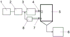
FIG. 1 is a schematic view of an energy-saving device for automobile electrophoresis;
in the figure: 1-first degreasing tank, 2-second degreasing tank, 3-flood flushing tank, 4-first valve, 5-standby degreasing tank, 6-dirt collecting tank, 7-second valve, and 8-filter.
Detailed Description
The present invention will be further explained with reference to the drawings and examples.
Example 1: the pretreatment electrophoresis tank inverting device comprises a first degreasing tank, a second degreasing tank and a flood washing tank which are sequentially connected through a pipeline; and when the regional tank dumping is carried out every week, discharging 30 tons of tank liquor in the flood washing area, pouring the degreasing 1 area into the flood washing area, and pouring the degreasing 2 area into the degreasing 1 area.
The degreasing wastewater is produced by adopting the device every year: 30 x 52=1560 ton; consumption of deionized water every year: 30 x 52=1560 ton.
Example 2: an automobile electrophoresis energy-saving device comprises a first degreasing tank 1, a second degreasing tank 2 and a flood washing tank 3 which are sequentially connected through pipelines; still including being equipped with degrease groove 5, the liquid outlet of flood flushing tank 3 is equipped with the inlet of degrease groove 5 through the pipeline intercommunication, the liquid outlet of being equipped with degrease groove 5 is through the inlet of pipeline intercommunication flood effluent groove 3.
In this embodiment, the liquid outlet of the flood washing tank 3 is communicated with the liquid inlet of the standby degreasing tank 5 through a first pipeline, and the first pipeline is provided with a first valve 4; the liquid outlet of the standby degreasing tank 5 is communicated with the liquid inlet of the flood flushing tank 3 through a second pipeline, and a second valve 7 is arranged on the second pipeline.
In this embodiment, the first pipeline and the second pipeline are both connected to a sidewall of the standby degreasing tank 5 and communicated with an inner cavity of the standby degreasing tank 5, and a connection position of the first pipeline is higher than that of the second pipeline; a filter 8 is arranged on the second pipeline; and a water pump is arranged at the end part of the second pipeline. In the specific working process, liquid discharged by the flood washing tank 3 is converged into the standby degreasing tank 5 through a first pipeline; after 12 hours of standing in the degreasing tank 5, the upper clear liquid flows out through a second pipeline communicated with the side wall, and returns to the flood washing area after primary filtration.
In this embodiment, the degreasing preparation tank 5 is cylindrical, an inner cavity is formed in the side wall of the degreasing preparation tank, and the bottom of the degreasing preparation tank is inverted cone-shaped; a sewage draining outlet is arranged at the position of the conical end of the device; the sewage draining port is connected with one end of a sewage draining pipeline, and the other end of the sewage draining pipeline is communicated with the inner cavity of the sewage collecting groove; in the specific working process, after the settled upper clear liquid flows out through the second pipeline, the residual tank liquid is discharged to the sewage collection tank through the sewage discharge pipeline for treatment.
In this embodiment, operating personnel can regularly change the liquid to the whole evacuation of tank liquor, prevents that the too much unable filterable residue or rotten that can appear of tank liquor use number of times from causing the influence to the life of electrophoresis effect or equipment.
In the embodiment, the device further comprises a controller; the first valve 4 and the second valve 7 are both electrically connected with the controller; the controller can control the opening and closing of the valve. Degreasing wastewater was produced annually in this example: 10 x 52=520 tons; consumption of deionized water every year: 10 × 52=520 tons.
The cost of disposing waste water is 10 yuan per ton, deionized water is 16 yuan per ton, and the comparison between the embodiment 1 and the embodiment 2 shows that the embodiment 2 saves 1040 x 10+1040 x 16=27040 yuan in total year, not only filters the liquid in the flood rinsing tank 3, but also rinses the workpiece, thus not causing waste of water resource and reducing the workload of tank switching.
The above are only embodiments of the present invention, and are not intended to limit the present invention, and to those skilled in the art, the present invention can have the combination and modification of the above various technical features, and those skilled in the art can replace the modifications, equivalents, or use the structure or method of the present invention in other fields to achieve the same effect without departing from the spirit and scope of the present invention, and all belong to the protection scope of the present invention.
Claims (8)
1. An automobile electrophoresis energy-saving device comprises a first degreasing tank, a second degreasing tank and a flood washing tank which are sequentially connected through pipelines; the method is characterized in that: the device is characterized by further comprising a degreasing tank, wherein a liquid outlet of the flood flushing tank is communicated with a liquid inlet of the degreasing tank through a pipeline, the liquid outlet of the degreasing tank is communicated with a liquid inlet of the flood discharging tank through a pipeline, and a control valve is arranged on the pipeline.
2. The automotive electrophoresis energy-saving device of claim 1, wherein: the liquid outlet of the flood washing tank is communicated with the liquid inlet of the degreasing tank through a first pipeline; and the liquid outlet of the degreasing tank is communicated with the liquid inlet of the flood flushing tank through a second pipeline.
3. The automotive electrophoresis energy-saving device of claim 2, wherein: the control valve comprises a first valve and a second valve, and the first valve is arranged on the first pipeline; the second valve is arranged on the second pipeline.
4. The automotive electrophoresis energy-saving device of claim 3, wherein: the first pipeline and the second pipeline are both connected to the side wall of the standby degreasing tank and communicated with the inner cavity of the standby degreasing tank, and the first pipeline is higher than the second pipeline.
5. The automotive electrophoresis energy-saving device of claim 3, wherein: the control valve further comprises a controller; the first valve and the second valve are electrically connected with the controller.
6. The automotive electrophoresis energy-saving device of claim 1, wherein: the degreasing tank is cylindrical and is provided with an inner cavity inside the side wall, and the bottom of the degreasing tank is inverted cone-shaped.
7. The automotive electrophoresis energy-saving device of claim 1, wherein: a drain outlet is formed in the bottom of the degreasing tank; the sewage draining outlet is connected with one end of a sewage draining pipeline, and the other end of the sewage draining pipeline is communicated with the inner cavity of the sewage collecting groove.
8. The automotive electrophoresis energy-saving device of claim 2, wherein: and a filter is arranged on the second pipeline.
Priority Applications (1)
| Application Number | Priority Date | Filing Date | Title |
|---|---|---|---|
| CN202120225084.4U CN214244653U (en) | 2021-01-27 | 2021-01-27 | Automobile electrophoresis energy-saving device |
Applications Claiming Priority (1)
| Application Number | Priority Date | Filing Date | Title |
|---|---|---|---|
| CN202120225084.4U CN214244653U (en) | 2021-01-27 | 2021-01-27 | Automobile electrophoresis energy-saving device |
Publications (1)
| Publication Number | Publication Date |
|---|---|
| CN214244653U true CN214244653U (en) | 2021-09-21 |
Family
ID=77796216
Family Applications (1)
| Application Number | Title | Priority Date | Filing Date |
|---|---|---|---|
| CN202120225084.4U Active CN214244653U (en) | 2021-01-27 | 2021-01-27 | Automobile electrophoresis energy-saving device |
Country Status (1)
| Country | Link |
|---|---|
| CN (1) | CN214244653U (en) |
Cited By (1)
| Publication number | Priority date | Publication date | Assignee | Title |
|---|---|---|---|---|
| CN114653556A (en) * | 2022-03-16 | 2022-06-24 | 岚图汽车科技有限公司 | Novel flood hot washing process for pretreatment before coating and multifunctional tank |
-
2021
- 2021-01-27 CN CN202120225084.4U patent/CN214244653U/en active Active
Cited By (1)
| Publication number | Priority date | Publication date | Assignee | Title |
|---|---|---|---|---|
| CN114653556A (en) * | 2022-03-16 | 2022-06-24 | 岚图汽车科技有限公司 | Novel flood hot washing process for pretreatment before coating and multifunctional tank |
Similar Documents
| Publication | Publication Date | Title |
|---|---|---|
| CN217069899U (en) | Workpiece water circulation flushing device of electroplating equipment | |
| CN202270453U (en) | Waste gas purifying system in metal acid cleaning | |
| CN104959337A (en) | Coating workpiece reverse backflow cleaning method | |
| CN103055683A (en) | Electroplating acid-base waste gas treatment device based on treating waste with waste | |
| CN216825077U (en) | Alkali liquor purification and recovery device based on cluster filtration method | |
| CN105063733B (en) | A kind of vertical electroplating production facility | |
| CN216737903U (en) | High-pressure automatic descaling device | |
| CN101869893A (en) | Pulsating cleaning method | |
| CN105040078B (en) | A kind of vertical electroplating cleaning system | |
| CN212669284U (en) | Membrane pool with sludge concentration function | |
| CN215924610U (en) | Car washing wastewater purification system of car washer | |
| CN110590004A (en) | Industrial water treatment device and self-cleaning mechanism thereof | |
| CN218232038U (en) | A wastewater biochemical MBR treatment system | |
| CN107020265A (en) | A kind of high-efficiency washing device | |
| CN223674463U (en) | A treatment device for removing heavy metals from leachate | |
| CN104907277B (en) | Cleaning by degreasing mechanism | |
| CN111014141A (en) | Cleaning equipment for remanufacturing of automobile engine cylinder cover | |
| CN203270081U (en) | Electroplating liquid filtering device | |
| CN205216406U (en) | Active carbon belt cleaning device and active carbon water purification system that can on -line regeneration | |
| CN114653556B (en) | A new torrent hot water washing process and multi-functional tank body for pre-painting treatment | |
| CN220223952U (en) | Multi-region joint transportation structure for sludge dewatering | |
| CN219861631U (en) | Electrophoretic coating impurity removing mechanism | |
| CN215161640U (en) | Pickling bonderizing waste water treatment equipment | |
| CN211386066U (en) | Treatment equipment for reducing emission | |
| CN201519520U (en) | Dirty alkali liquor recovery unit |
Legal Events
| Date | Code | Title | Description |
|---|---|---|---|
| GR01 | Patent grant | ||
| GR01 | Patent grant |