CN214242836U - A door panel feeding device - Google Patents

A door panel feeding device Download PDF

Info

Publication number
CN214242836U
CN214242836U CN202022691080.3U CN202022691080U CN214242836U CN 214242836 U CN214242836 U CN 214242836U CN 202022691080 U CN202022691080 U CN 202022691080U CN 214242836 U CN214242836 U CN 214242836U
Authority
CN
China
Prior art keywords
guide rod
suction cup
guide
mounting seat
suction cups
Prior art date
Legal status (The legal status is an assumption and is not a legal conclusion. Google has not performed a legal analysis and makes no representation as to the accuracy of the status listed.)
Expired - Fee Related
Application number
CN202022691080.3U
Other languages
Chinese (zh)
Inventor
赵文华
王志强
Current Assignee (The listed assignees may be inaccurate. Google has not performed a legal analysis and makes no representation or warranty as to the accuracy of the list.)
Foshan Wharton Equipment Technology Co ltd
Original Assignee
Foshan Wharton Equipment Technology Co ltd
Priority date (The priority date is an assumption and is not a legal conclusion. Google has not performed a legal analysis and makes no representation as to the accuracy of the date listed.)
Filing date
Publication date
Application filed by Foshan Wharton Equipment Technology Co ltd filed Critical Foshan Wharton Equipment Technology Co ltd
Priority to CN202022691080.3U priority Critical patent/CN214242836U/en
Application granted granted Critical
Publication of CN214242836U publication Critical patent/CN214242836U/en
Expired - Fee Related legal-status Critical Current
Anticipated expiration legal-status Critical

Links

Images

Landscapes

  • Manipulator (AREA)

Abstract

一种门板上料装置,包括龙门架,龙门架上设置有一横梁;活动座,活动座由第一驱动单元带动可沿横梁的长度方向运动;立柱,立柱由第二驱动单元带动可沿龙门架的高度方向相对于活动座运动;安装座,该安装座上设置有两第一吸盘、两第二吸盘,两第二吸盘分布于两第一吸盘的外侧,第一吸盘和第二吸盘上均固定有沿龙门架高度方向延伸的导向杆,导向杆活动的穿接在安装座上,且安装座与导向杆之间设置有将导向杆向下顶推的弹性元件;安装座上设置有第三驱动单元,第三驱动单元用于将第一吸盘上固定的导向杆向上顶推。本实用新型可根据门板的尺寸大小,对应的选择吸盘,在满足门板上料的前提下,减小工作时候吸盘的数量,从而降低气泵的负荷。

Figure 202022691080

A door plate feeding device, comprising a gantry frame on which a beam is arranged; a movable seat, which is driven by a first driving unit and can move along the length of the beam; a column, which is driven by a second driving unit and can move along the gantry frame The height direction of the movable seat moves relative to the movable seat; the mounting seat is provided with two first suction cups and two second suction cups, and the two second suction cups are distributed on the outside of the two first suction cups, and the first suction cup and the second suction cup are both A guide rod extending along the height direction of the gantry is fixed, the guide rod is movably connected to the mounting seat, and an elastic element that pushes the guide rod downward is arranged between the mounting seat and the guide rod; Three drive units, the third drive unit is used to push up the guide rod fixed on the first suction cup. The utility model can select the suction cups correspondingly according to the size of the door panel, and on the premise of satisfying the door panel material, the number of the suction cups during operation is reduced, thereby reducing the load of the air pump.

Figure 202022691080

Description

Door plant loading attachment
Technical Field
The utility model relates to a door plant processing technology field, concretely relates to door plant loading attachment.
Background
Door plant adds man-hour, need shift to the transport mechanism on the production line in proper order with the door plant of range upon range of placing, this often accomplishes through loading attachment, traditional loading attachment is the both sides through the tight door plant of tongs clamp, move the door plant to transport mechanism on, when the door plant piles up, just need reserve the clearance between adjacent door plant to ensure that the tongs can be by the side centre gripping door plant of door plant, consequently, lead to in certain height within range, the quantity that piles up the door plant reduces, the space that occupies is great. At present, some of the panels adopt sucking discs to suck the door plates and then feed the door plates, but the sucking discs are more, the requirement on an air pump is higher, and the door plates cannot be adjusted according to different sizes.
SUMMERY OF THE UTILITY MODEL
Not enough to prior art, the utility model aims at providing a door plant loading attachment, it can select corresponding sucking disc to the door plant of equidimension not, reduces the load of air pump.
In order to achieve the above purpose, the utility model adopts the following technical scheme:
a door panel loading device, comprising:
the portal frame is provided with a beam;
the movable seat is arranged on the cross beam and is driven by a first driving unit to move along the length direction of the cross beam;
the upright post is arranged on the movable seat and is driven by a second driving unit to move relative to the movable seat along the height direction of the portal frame;
the device comprises a mounting seat fixed on an upright post, wherein two opposite first suckers and two opposite second suckers are arranged on the mounting seat, the two second suckers are distributed on the outer sides of the two first suckers, guide rods extending along the height direction of a portal frame are fixed on the first suckers and the second suckers, the guide rods movably penetrate through the mounting seat, and an elastic element for pushing the guide rods downwards is arranged between the mounting seat and the guide rods;
the mounting seat is provided with a third driving unit which is used for pushing the guide rod fixed on the first sucker upwards.
The two ends of the first sucker are respectively fixed with a guide rod, a connecting plate is fixedly connected to the tops of the guide rods at the two ends of the first sucker, the third driving unit is an air cylinder, the cylinder body of the air cylinder is fixedly connected to the mounting seat, and the telescopic rod extends upwards and is connected to the middle of the connecting plate.
The elastic element is a spring sleeved outside the guide rod.
The two sides of the mounting seat are respectively provided with a longitudinal beam, the longitudinal beam is fixedly connected with a plurality of guide blocks, and the guide rods on the first suction cup and the second suction cup are correspondingly penetrated in guide holes formed in the guide blocks one to one.
The lateral surface of longeron is provided with the draw-in groove that extends along its length direction, and the draw-in groove is gliding to be provided with the joint piece, and the cross-under has fixing bolt on the guide block, and fixing bolt's inboard end spiro union is on the joint piece, and the both sides butt of joint piece is at the internal surface of the both sides edge of draw-in groove.
The beam is provided with a first linear guide rail and a first rack which extend along the length direction of the beam, the movable seat is slidably arranged on the first linear guide rail, the first driving unit is a first motor, and the output end of the first motor is provided with a first gear which is meshed with the first rack; the upright post is provided with a second linear guide rail and a second rack, the second linear guide rail extends along the height direction of the portal frame, the movable seat is fixed with a slide block in sliding fit with the second linear guide rail, the second driving unit is a second motor, and a second gear meshed with the second rack is installed at the output end of the second motor.
The beneficial effects of the utility model reside in that:
compared with the prior art, the utility model discloses can be according to the size of door plant, the selection sucking disc that corresponds reduces the quantity of during operation sucking disc under the prerequisite that satisfies the door plant material loading to reduce the load of air pump.
Drawings
Fig. 1 is a schematic structural view of the present invention;
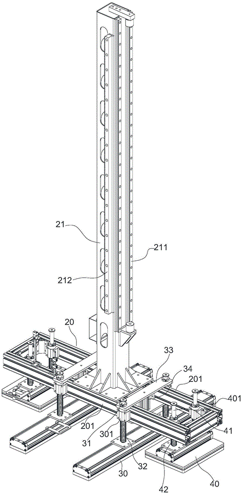
FIG. 2 is a schematic structural view of the mounting base of FIG. 1;
fig. 3 is a schematic view of the connection between the guide block and the longitudinal beam in fig. 2.
Detailed Description
The invention will be further described with reference to the accompanying drawings and specific embodiments:
as shown in fig. 1, 2, and 3, for the utility model discloses a door plate feeding device, it includes portal frame, sliding seat 22, stand 21, mount pad 20, wherein, the portal frame includes the crossbeam 10 that is located its top, and sliding seat 22 is installed on crossbeam 10, specifically, is provided with first linear guide 101 on crossbeam 10, and sliding seat 22 is installed on this first linear guide 101, is provided with first drive unit on sliding seat 22, is used for driving sliding seat 22 to follow first linear guide 101 reciprocating motion, namely moves along the length direction of crossbeam 10; the stand 21 is movably installed on the movable seat 22, and it can be along extending the direction of height of portal frame for the up-and-down motion of movable seat 22, specifically, be provided with the second linear guide 211 that extends along the direction of height of portal frame on stand 21, be provided with on the movable seat 22 with second linear guide 211 sliding fit's slider, be provided with a second drive unit on the movable seat 22, this second drive unit is used for driving stand 21 along the extending direction reciprocating motion of second linear guide 211, follows the direction of height motion of portal frame promptly. The mounting base 20 is fixedly connected to the bottom end part of the upright post 21, two first suction cups 30 and two second suction cups 40 are connected below the mounting base 20, the two first suction cups 30 are oppositely arranged, and the two second suction cups 40 are respectively positioned at the outer sides of the two first suction cups 30 and oppositely arranged; the guide rod 31 is fixedly connected to the first suction cup 30, the guide rod 41 is fixed to the second suction cup 40, the guide rod 31 and the guide rod 41 both extend in the height direction of the portal frame, and the guide rod 31 and the guide rod 41 both extend upwards and then slidably penetrate through the mounting base 20, that is, the first suction cup 30 and the second suction cup 40 are both floatingly mounted on the mounting base 20, and elastic elements are arranged among the guide rod 31, the guide rod 41 and the mounting base 20 and used for pushing the guide rod 31 and the guide rod 41 downwards all the time. A third driving unit is further disposed on the mounting base 20, and the third driving unit is configured to push the guide rod 31 of the first suction cup 30 upward.
The utility model discloses during the material loading, mount pad 20 is downward in the area of stand 21, and the downstream makes the upper surface of first sucking disc 30 and the contact door plant of second sucking disc 40, utilizes elastic element to play the effect of buffering, prevents that the upper surface rigidity of first sucking disc 30 and second sucking disc 40 and door plant from colliding, after adsorbing the door plant, utilizes first drive unit and second drive unit to drive movable seat 22 and removes, places the door plant on the conveying mechanism on the production line. When the door panels with different sizes are used, the third driving unit can be selectively used for driving the first suction cup 30 to ascend or descend, for example, when the door panels with larger sizes are used, the first suction cup 30 can be descended to the same height as the second suction cup 40, when the door panels are sucked, the first suction cup 30 and the second suction cup 40 work simultaneously, when the door panels with smaller sizes are used, the first suction cup 30 is lifted, only the second suction cup 40 is used for lifting the door panels, and at the moment, the two second suction cups 40 are respectively used for lifting one door panel with smaller sizes. Compared with the prior art, the utility model discloses can be according to the size of door plant, the selection sucking disc that corresponds reduces the quantity of during operation sucking disc under the prerequisite that satisfies the door plant material loading to reduce the load of air pump.
The utility model discloses in, a guide bar 31 is fixed respectively at the both ends of first sucking disc 30, is fixed with a connecting plate 33 between the top portion of these two guide bars 31, and this connecting rod 33 is located the top of mount pad 20, and foretell third drive unit is a cylinder 34, and the cylinder body of this cylinder 34 is fixed on mount pad 20, and the telescopic link upwards extends and is connected at the middle part of connecting plate 33, utilizes this cylinder 34, can be with first sucking disc 30 lifting. Of course, the third driving unit may be an oil cylinder or the like.
The elastic element is a spring, and specifically, a spring 32 is sleeved outside the guide rod 31, and a spring 42 is sleeved outside the guide rod 41.
A longitudinal beam 201 is respectively arranged on two sides of the mounting seat 20, a plurality of guide blocks 301 and guide blocks 401 are fixedly connected to the longitudinal beam 201, wherein the guide rod 31 is movably inserted into a guide hole of the guide block 301 upwards, and the guide rod 41 is movably inserted into a guide hole of the guide block 401 upwards, so that the first suction cup 30 and the second suction cup 40 are prevented from deflecting when moving upwards and downwards; the longitudinal beam 201 is an aluminum profile, a clamping groove 202 extending along the length direction of the longitudinal beam is formed in the outer side face of the longitudinal beam, a plurality of clamping blocks 203 are embedded in the clamping groove 202, bolt holes are formed in the clamping blocks 203, fixing bolts 204 are arranged on the guide block 301 and the guide block 401 in a penetrating mode, inner side ends of the fixing bolts 204 correspondingly penetrate through bolt holes in one clamping block 203, two sides of each clamping block 203 respectively abut against the inner surfaces of two side edges of the clamping groove 202, when the fixing bolts 204 are screwed down, the clamping blocks 203 tightly press two sides of the clamping groove 202, the guide block 301 and the guide block 401 are fixed on the longitudinal beam 201, when the positions of the first suction disc 30 and the second suction disc 40 need to be adjusted, the fixing bolts 204 are unscrewed, the positions of the clamping blocks 203 are adjusted along the length direction of the longitudinal beam 201, and the fixing bolts 204 are locked again
In the present invention, the first rack 102 is disposed on the beam 10, the first driving unit is a first motor 23 mounted on the movable seat 22, a first gear is mounted at an output end of the first motor 23, and the first gear is engaged with the first rack 102, so that the motor 23 can drive the movable seat 22 to slide along the length direction of the beam 10; set up the second rack 212 that extends along portal frame direction of height on stand 21, second drive unit is for installing second motor 24 on sliding seat 22, and a second gear is installed to the output of second motor 24, and this second gear and the meshing of second rack 212 start second motor 24, can make stand 21 for sliding seat 22 up-and-down motion, drive mount pad 20 up-and-down motion then.
The foregoing is merely a preferred embodiment of the present invention, and further details of the present invention are described in conjunction with specific preferred embodiments, which should not be construed as limiting the practice of the invention to these descriptions. Any modification, equivalent replacement, and improvement made within the spirit and principle of the present invention should be included in the protection scope of the present invention.

Claims (6)

1.一种门板上料装置,其特征在于,包括:1. a door plate feeding device, is characterized in that, comprises: 龙门架,该龙门架上设置有一横梁;a gantry, a beam is arranged on the gantry; 安装在横梁上的活动座,该活动座由一第一驱动单元带动可沿横梁的长度方向运动;a movable seat installed on the beam, the movable seat is driven by a first drive unit to move along the length of the beam; 安装在活动座上的立柱,该立柱由一第二驱动单元带动可沿龙门架的高度方向相对于活动座运动;a column installed on the movable seat, the column is driven by a second drive unit to move relative to the movable seat along the height direction of the gantry; 固定在立柱上的安装座,该安装座上设置有两个相对的第一吸盘、以及两个相对的第二吸盘,两第二吸盘分布于两第一吸盘的外侧,第一吸盘和第二吸盘上均固定有沿龙门架高度方向延伸的导向杆,导向杆活动的穿接在安装座上,且安装座与导向杆之间设置有将导向杆向下顶推的弹性元件;The mounting seat fixed on the column, the mounting seat is provided with two opposite first suction cups and two opposite second suction cups, the two second suction cups are distributed on the outside of the two first suction cups, the first suction cup and the second suction cup A guide rod extending along the height direction of the gantry is fixed on the suction cups, the guide rod is movably connected to the mounting seat, and an elastic element that pushes the guide rod downward is arranged between the mounting seat and the guide rod; 其中,在安装座上设置有一第三驱动单元,该第三驱动单元用于将第一吸盘上固定的导向杆向上顶推。Wherein, a third driving unit is arranged on the mounting seat, and the third driving unit is used to push upward the guide rod fixed on the first suction cup. 2.如权利要求1所述的门板上料装置,其特征在于,第一吸盘的两端分别固定有一导向杆,位于第一吸盘两端的导向杆的顶部固定连接有一连接板,第三驱动单元为一气缸,该气缸的缸体固定连接在安装座上、伸缩杆向上延伸并连接在连接板的中部。2 . The door panel feeding device according to claim 1 , wherein a guide rod is fixed at both ends of the first suction cup, a connecting plate is fixedly connected to the top of the guide rod at both ends of the first suction cup, and the third driving unit It is a cylinder, the cylinder body of the cylinder is fixedly connected to the mounting seat, and the telescopic rod extends upward and is connected to the middle of the connecting plate. 3.如权利要求1所述的门板上料装置,其特征在于,弹性元件为套设在导向杆外部的弹簧。3 . The door panel feeding device according to claim 1 , wherein the elastic element is a spring sleeved on the outside of the guide rod. 4 . 4.如权利要求1所述的门板上料装置,其特征在于,安装座的两侧分别设置有一纵梁,纵梁上固定连接有多个导向块,第一吸盘和第二吸盘上的导向杆一一对应的穿接在导向块上开设的导向孔中。4 . The door panel feeding device according to claim 1 , wherein a longitudinal beam is respectively provided on both sides of the mounting seat, and a plurality of guide blocks are fixedly connected to the longitudinal beam, and the guide blocks on the first suction cup and the second suction cup are fixedly connected. 5 . The rods are threaded through the guide holes provided on the guide blocks in a one-to-one correspondence. 5.如权利要求4所述的门板上料装置,其特征在于,纵梁的外侧面设置有沿其长度方向延伸的卡槽,卡槽滑动的设置有卡接块,导向块上穿接有固定螺栓,固定螺栓的内侧端螺接在卡接块上,卡接块的两侧抵接在卡槽的两侧边缘的内表面。5 . The door panel feeding device according to claim 4 , wherein the outer side of the longitudinal beam is provided with a card slot extending along its length direction, the card slot is slidably provided with a snap block, and the guide block is penetrated with a card slot. 6 . A fixing bolt, the inner end of the fixing bolt is screwed on the clamping block, and the two sides of the clamping block abut on the inner surfaces of the two sides of the clamping slot. 6.如权利要求1所述的门板上料装置,其特征在于,横梁上设置有沿其长度方向延伸的第一直线导轨、以及第一齿条,活动座滑动的安装在第一直线导轨上,第一驱动单元为第一电机,第一电机的输出端安装有与第一齿条啮合的第一齿轮;立柱上设置沿龙门架的高度方向延伸的第二直线导轨、以及第二齿条,活动座固定有与第二直线导轨滑动配合的滑块,第二驱动单元为第二电机,第二电机的输出端安装有与第二齿条啮合的第二齿轮。6 . The door panel feeding device according to claim 1 , wherein the beam is provided with a first linear guide rail extending along its length direction, and a first rack, and the movable seat is slidably installed on the first straight line. 7 . On the guide rail, the first drive unit is a first motor, and the output end of the first motor is installed with a first gear that meshes with the first rack; The rack, the movable seat is fixed with a sliding block slidingly matched with the second linear guide rail, the second driving unit is a second motor, and the output end of the second motor is installed with a second gear meshing with the second rack.
CN202022691080.3U 2020-11-19 2020-11-19 A door panel feeding device Expired - Fee Related CN214242836U (en)

Priority Applications (1)

Application Number Priority Date Filing Date Title
CN202022691080.3U CN214242836U (en) 2020-11-19 2020-11-19 A door panel feeding device

Applications Claiming Priority (1)

Application Number Priority Date Filing Date Title
CN202022691080.3U CN214242836U (en) 2020-11-19 2020-11-19 A door panel feeding device

Publications (1)

Publication Number Publication Date
CN214242836U true CN214242836U (en) 2021-09-21

Family

ID=77733265

Family Applications (1)

Application Number Title Priority Date Filing Date
CN202022691080.3U Expired - Fee Related CN214242836U (en) 2020-11-19 2020-11-19 A door panel feeding device

Country Status (1)

Country Link
CN (1) CN214242836U (en)

Cited By (1)

* Cited by examiner, † Cited by third party
Publication number Priority date Publication date Assignee Title
CN115255182A (en) * 2022-08-08 2022-11-01 山东北辰机电设备股份有限公司 A cantilever type automatic loading and unloading device for pressing heat exchange plates

Cited By (1)

* Cited by examiner, † Cited by third party
Publication number Priority date Publication date Assignee Title
CN115255182A (en) * 2022-08-08 2022-11-01 山东北辰机电设备股份有限公司 A cantilever type automatic loading and unloading device for pressing heat exchange plates

Similar Documents

Publication Publication Date Title
CN110436193B (en) Whole row transfer robot of strip timber
CN107934544B (en) A kind of plate automatic feeding equipment and using method thereof
CN213084717U (en) A plate feeding device and conveying line
CN108544882A (en) A kind of engraving machine of automatic loading/unloading
CN206306123U (en) A kind of two-pass sucker manipulator
CN105855979B (en) Intelligent workpiece processing equipment
CN210237453U (en) A super thick glass plate cutting machine
CN205187345U (en) Vacuum suction board machine
CN120326168A (en) Laser marking device and method thereof
CN211969886U (en) Packaging bag feeding device
CN220840221U (en) Clamp
CN219170909U (en) A manipulator with auxiliary lift
CN217920348U (en) Automatic plate picking and stacking machine
CN209794838U (en) Efficient automatic screen printing machine
CN216807270U (en) Steel plate sucker gripper
CN114275572B (en) Automatic feeding device and automatic feeding and discharging method for PET (polyethylene terephthalate) film
CN215710013U (en) Metal cap adsorption transfer device
CN110834316A (en) Forming manipulator
CN216444556U (en) An automatic loading and unloading machine for melamine veneer with efficient circulation operation
CN210732534U (en) Vacuum film self-adsorption box film pressing cutting mechanism
CN213562621U (en) A installation fixing device for curved surface glass processing's manipulator
CN211680612U (en) Welding machine equipment for photovoltaic module battery string bus bar
CN210260308U (en) Workpiece transfer device of glass screen printing machine
CN211255129U (en) A feed bin elevating gear for circuit board automated production
CN222485001U (en) A feeding mechanism for circuit board edge grinding processing to prevent material stacking

Legal Events

Date Code Title Description
GR01 Patent grant
GR01 Patent grant
CF01 Termination of patent right due to non-payment of annual fee

Granted publication date: 20210921