CN214238299U - Manipulator device of automatic equipment - Google Patents
Manipulator device of automatic equipment Download PDFInfo
- Publication number
- CN214238299U CN214238299U CN202120188533.2U CN202120188533U CN214238299U CN 214238299 U CN214238299 U CN 214238299U CN 202120188533 U CN202120188533 U CN 202120188533U CN 214238299 U CN214238299 U CN 214238299U
- Authority
- CN
- China
- Prior art keywords
- fixedly connected
- slider
- inverted
- motor
- vacuum pump
- Prior art date
- Legal status (The legal status is an assumption and is not a legal conclusion. Google has not performed a legal analysis and makes no representation as to the accuracy of the status listed.)
- Expired - Fee Related
Links
- 230000006978 adaptation Effects 0.000 claims description 3
- 238000001125 extrusion Methods 0.000 abstract description 9
- 238000003825 pressing Methods 0.000 abstract description 6
- 238000005096 rolling process Methods 0.000 abstract description 6
- 238000000034 method Methods 0.000 abstract description 5
- 230000008569 process Effects 0.000 abstract description 5
- 230000008859 change Effects 0.000 abstract description 4
- 230000004075 alteration Effects 0.000 description 1
- 230000008485 antagonism Effects 0.000 description 1
- 230000009286 beneficial effect Effects 0.000 description 1
- 230000000694 effects Effects 0.000 description 1
- 238000012986 modification Methods 0.000 description 1
- 230000004048 modification Effects 0.000 description 1
- 230000009467 reduction Effects 0.000 description 1
- 238000006467 substitution reaction Methods 0.000 description 1
Images


Landscapes
- Manipulator (AREA)
Abstract
The utility model discloses an automatic change manipulator device of equipment, the on-line screen storage device comprises a base, the interior diapire fixedly connected with gear motor of base, gear motor's output fixedly connected with rolling disc, the last fixed surface of rolling disc is connected with the support that appears of falling L, the surface sliding connection who falls the support that appears of L has the slip pipe that appears of falling L, the inner wall sliding connection who falls the L slip pipe has the lift post, the bottom fixedly connected with fixed block of lift post, the spout has been seted up to the lower surface of fixed block, and the inner wall sliding connection of spout has the slider. This automation equipment's manipulator device through setting up accommodate motor, positive and negative tooth screw rod, slider, pressing from both sides tight piece, vacuum pump and sucking disc, and the start-up of the accommodate motor of being convenient for makes positive and negative tooth screw rod drive two sliders and removes, and the vacuum pump takes the inside air of sucking disc out simultaneously, utilizes two supplementary tight pieces of clamp of sucking disc to press from both sides the work piece tightly to effectively avoid the phenomenon that the work piece moving process that anti extrusion ability is poor drops.
Description
Technical Field
The utility model relates to a manipulator technical field specifically is a manipulator device of automation equipment.
Background
Since the 21 st century, with the development of economy and social progress, the countries in the world increasingly attach importance to the development of science and technology. Since our country has developed science and technology rapidly since the strategy of science and education, the number of industrial manipulators replacing manpower is gradually increased.
When a workpiece with poor anti-extrusion capacity is clamped, in order to protect the workpiece, the clamping force of a common manipulator is reduced, the clamping force is insufficient, and the workpiece is easy to drop and damage in the moving process.
We therefore propose a robot device for an automated apparatus.
Disclosure of Invention
An object of the utility model is to provide an automation equipment's manipulator device to solve the problem that proposes among the above-mentioned background art.
In order to achieve the above object, the utility model provides a following technical scheme: the utility model provides an automatic change manipulator device of equipment, includes the base, the interior diapire fixedly connected with gear motor of base, gear motor's output fixedly connected with rolling disc, the last fixed surface of rolling disc is connected with the support that appears of falling L, the surface sliding connection who falls the L shape support has the slip pipe that appears of falling L, the inner wall sliding connection who falls the L shape slip pipe has the lift post, the bottom fixedly connected with fixed block of lift post, the spout has been seted up to the lower surface of fixed block, and the inner wall sliding connection of spout has the slider, the recess has been seted up to the lower surface of slider, and the inner wall of recess rotates through the bearing and is connected with the axis of rotation, the tight piece of bottom fixedly connected with clamp of axis of rotation, the standing groove has been seted up to the side of pressing from both sides tight piece, and the inner wall of standing groove is provided with sucking disc and vacuum pump respectively.
Preferably, the outer surface of the inverted L-shaped sliding pipe is fixedly connected with two hydraulic telescopic rods, and the telescopic ends of the two hydraulic telescopic rods are respectively fixedly connected with the outer surfaces of the inverted L-shaped support and the lifting column.
Preferably, the quantity of slider is two, the side fixedly connected with accommodate motor of fixed block, accommodate motor's the positive and negative tooth screw rod of output fixedly connected with, two the screw hole with positive and negative tooth screw rod adaptation is all seted up to the side of slider.
Preferably, the cavity has been seted up to the inside of slider, the top of axis of rotation extends to the inside of cavity and fixedly connected with driven gear, the lower fixed surface of slider is connected with servo motor, servo motor's output fixedly connected with and driven gear engaged with driving gear.
Preferably, one end of the suction cup is connected with an output end pipeline of the vacuum pump.
Preferably, one side of the clamping block, which is far away from the placing groove, is fixedly connected with a rubber block.
Advantageous effects
The utility model provides an automatic change manipulator device of equipment possesses following beneficial effect:
1. this automation equipment's manipulator device through setting up accommodate motor, positive and negative tooth screw rod, slider, pressing from both sides tight piece, vacuum pump and sucking disc, and the start-up of the accommodate motor of being convenient for makes positive and negative tooth screw rod drive two sliders and removes, and the vacuum pump takes the inside air of sucking disc out simultaneously, utilizes two supplementary tight pieces of clamp of sucking disc to press from both sides the work piece tightly to effectively avoid the phenomenon that the work piece moving process that anti extrusion ability is poor drops.
2. This automation equipment's manipulator device through setting up servo motor, driving gear, driven gear, axis of rotation, pressing from both sides tight piece and block rubber, and the servo motor's of being convenient for start-up makes the driving gear drive driven gear and rotates to make and press from both sides tight piece and rotate, thereby convenient confrontation extrusion ability strong work piece presss from both sides and gets, and the practicality is stronger.
Drawings
FIG. 1 is a schematic view of a front cross-sectional structure of the present invention;
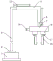
FIG. 2 is a schematic front view of the present invention;
fig. 3 is an enlarged schematic view of a portion a in fig. 1 according to the present invention.
In the figure: the device comprises a base 1, a speed reducing motor 2, a rotating disc 3, an inverted L-shaped support 4, an inverted L-shaped sliding tube 5, a lifting column 6, a fixed block 7, a sliding block 8, a rotating shaft 9, a clamping block 10, a sucking disc 11, a vacuum pump 12, a hydraulic telescopic rod 13, an adjusting motor 14, a screw rod with 15 positive and negative teeth, a driven gear 16, a servo motor 17, a driving gear 18 and a rubber block 19.
Detailed Description
The technical solutions in the embodiments of the present invention will be described clearly and completely with reference to the accompanying drawings in the embodiments of the present invention, and it is obvious that the described embodiments are only some embodiments of the present invention, not all embodiments. Based on the embodiments in the present invention, all other embodiments obtained by a person skilled in the art without creative work belong to the protection scope of the present invention.
Referring to fig. 1-3, the present invention provides a technical solution: the utility model provides an automatic change manipulator device of equipment, the on-line screen storage device comprises a base 1, inner diapire fixedly connected with gear motor 2 of base 1, gear motor 2's output fixedly connected with rolling disc 3, the last fixed surface of rolling disc 3 is connected with down L shape support 4, the surface sliding connection of the support 4 that falls L shape has the slip tube 5 that falls L shape, the inner wall sliding connection of the slip tube 5 that falls L shape has lift post 6, two hydraulic telescoping rod 13 of the outer fixed surface of the slip tube 5 that falls L shape, the flexible end of two hydraulic telescoping rod 13 respectively with the outer fixed surface of the support 4 that falls L shape and lift post 6 is connected, the bottom fixedly connected with fixed block 7 of lift post 6.
The spout has been seted up to the lower surface of fixed block 7, and the inner wall sliding connection of spout has slider 8, and the quantity of slider 8 is two, and the side fixedly connected with adjusting motor 14 of fixed block 7, adjusting motor 14's the positive and negative tooth screw rod 15 of output fixedly connected with, the screw hole with the 15 adaptations of positive and negative tooth screw rod is all seted up to the side of two sliders 8.
The lower surface of slider 8 is seted up flutedly, and the inner wall of recess rotates through the bearing and is connected with axis of rotation 9, and the cavity has been seted up to slider 8's inside, and the top of axis of rotation 9 extends to the inside and the fixedly connected with driven gear 16 of cavity, and slider 8's lower fixed surface is connected with servo motor 17, and servo motor 17's output fixedly connected with and driven gear 16 meshed driving gear 18.
The tight piece 10 of bottom fixedly connected with clamp of axis of rotation 9, the standing groove has been seted up to the side of pressing from both sides tight piece 10, and the inner wall of standing groove is provided with sucking disc 11 and vacuum pump 12 respectively, press from both sides tight piece 10 one side fixedly connected with rubber block 19 of keeping away from the standing groove, the one end of sucking disc 11 and vacuum pump 12's output pipe connection, through setting up accommodate motor 14, positive and negative tooth screw rod 15, slider 8, press from both sides tight piece 10, vacuum pump 12 and sucking disc 11, it makes two slider 8 of positive and negative tooth screw rod 15 drive to be convenient for accommodate motor 14's start-up, vacuum pump 12 takes out sucking disc 11 inside air simultaneously, utilize sucking disc 11 to assist two tight pieces 10 of clamp and press from both sides the work piece tightly, thereby effectively avoid the phenomenon that the poor work piece moving process of anti-extrusion ability drops.
This automation equipment's manipulator device through setting up servo motor 17, driving gear 18, driven gear 16, axis of rotation 9, pressing from both sides tight piece 10 and block rubber 19, the start-up of servo motor 17 of being convenient for makes driving gear 18 drive driven gear 16 and rotates to make and press from both sides tight piece 10 and rotate, thereby the work piece that convenient antagonism extrusion capacity is strong is got, and the practicality is stronger.
The working principle is as follows: when the manipulator device of the automatic equipment is used, the reduction motor 2 is started to drive the device to rotate, the two hydraulic telescopic rods 13 stretch and retract to adjust the transverse position and the height of the manipulator, when a workpiece with poor extrusion resistance is clamped, the positive and negative threaded screws 15 are driven to move by the aid of the starting of the adjusting motor 14 to clamp the workpiece, the vacuum pump 12 is started to enable the suction disc 11 to be adsorbed with the workpiece, then the workpiece is moved, when the workpiece with high extrusion resistance is clamped, the servo motor 17 is started to enable the driving gear 18 to drive the driven gear 16 to rotate, the two rubber blocks 19 are rotated to the inner side to clamp the workpiece, and the phenomenon that the workpiece with poor extrusion resistance falls off in the moving process is effectively avoided by means of the manipulator device of the automatic equipment.
Although embodiments of the present invention have been shown and described, it will be appreciated by those skilled in the art that changes, modifications, substitutions and alterations can be made in these embodiments without departing from the principles and spirit of the invention, the scope of which is defined in the appended claims and their equivalents.
Claims (6)
1. The utility model provides an automation equipment's manipulator device, includes base (1), its characterized in that: the inner bottom wall of the base (1) is fixedly connected with a speed reducing motor (2), the output end of the speed reducing motor (2) is fixedly connected with a rotating disc (3), the upper surface of the rotating disc (3) is fixedly connected with an inverted L-shaped support (4), the outer surface of the inverted L-shaped support (4) is slidably connected with an inverted L-shaped sliding tube (5), the inner wall of the inverted L-shaped sliding tube (5) is slidably connected with a lifting column (6), the bottom end of the lifting column (6) is fixedly connected with a fixed block (7), the lower surface of the fixed block (7) is provided with a sliding groove, the inner wall of the sliding groove is slidably connected with a sliding block (8), the lower surface of the sliding block (8) is provided with a groove, the inner wall of the groove is rotatably connected with a rotating shaft (9) through a bearing, the bottom end of the rotating shaft (9) is fixedly connected with a clamping block (10), and the side surface of the clamping block (10) is provided with a placing groove, and the inner wall of the placing groove is respectively provided with a suction cup (11) and a vacuum pump (12).
2. The robot device of an automated apparatus according to claim 1, wherein: the outer fixed surface of the inverted L-shaped sliding pipe (5) is connected with two hydraulic telescopic rods (13), and the telescopic ends of the two hydraulic telescopic rods (13) are respectively fixedly connected with the outer surfaces of the inverted L-shaped support (4) and the lifting column (6).
3. The robot device of an automated apparatus according to claim 1, wherein: the quantity of slider (8) is two, the side fixedly connected with adjusting motor (14) of fixed block (7), the positive and negative tooth screw rod (15) of output fixedly connected with of adjusting motor (14), two the screw hole with positive and negative tooth screw rod (15) adaptation is all seted up to the side of slider (8).
4. The robot device of an automated apparatus according to claim 1, wherein: the cavity has been seted up to the inside of slider (8), the top of axis of rotation (9) extends to the inside and fixedly connected with driven gear (16) of cavity, the lower fixed surface of slider (8) is connected with servo motor (17), the output fixedly connected with of servo motor (17) and driven gear (16) engaged with driving gear (18).
5. The robot device of an automated apparatus according to claim 1, wherein: one end of the sucking disc (11) is connected with an output end pipeline of the vacuum pump (12).
6. The robot device of an automated apparatus according to claim 1, wherein: and a rubber block (19) is fixedly connected to one side of the clamping block (10) far away from the placing groove.
Priority Applications (1)
| Application Number | Priority Date | Filing Date | Title |
|---|---|---|---|
| CN202120188533.2U CN214238299U (en) | 2021-01-25 | 2021-01-25 | Manipulator device of automatic equipment |
Applications Claiming Priority (1)
| Application Number | Priority Date | Filing Date | Title |
|---|---|---|---|
| CN202120188533.2U CN214238299U (en) | 2021-01-25 | 2021-01-25 | Manipulator device of automatic equipment |
Publications (1)
| Publication Number | Publication Date |
|---|---|
| CN214238299U true CN214238299U (en) | 2021-09-21 |
Family
ID=77751964
Family Applications (1)
| Application Number | Title | Priority Date | Filing Date |
|---|---|---|---|
| CN202120188533.2U Expired - Fee Related CN214238299U (en) | 2021-01-25 | 2021-01-25 | Manipulator device of automatic equipment |
Country Status (1)
| Country | Link |
|---|---|
| CN (1) | CN214238299U (en) |
Cited By (1)
| Publication number | Priority date | Publication date | Assignee | Title |
|---|---|---|---|---|
| CN114654485A (en) * | 2022-03-30 | 2022-06-24 | 李俊标 | Manipulator device with adjustable manipulator distance |
-
2021
- 2021-01-25 CN CN202120188533.2U patent/CN214238299U/en not_active Expired - Fee Related
Cited By (2)
| Publication number | Priority date | Publication date | Assignee | Title |
|---|---|---|---|---|
| CN114654485A (en) * | 2022-03-30 | 2022-06-24 | 李俊标 | Manipulator device with adjustable manipulator distance |
| CN114654485B (en) * | 2022-03-30 | 2023-11-03 | 北京鼎元霖环保科技有限公司 | Manipulator device with adjustable manipulator spacing |
Similar Documents
| Publication | Publication Date | Title |
|---|---|---|
| CN209190296U (en) | Clamping device is used in a kind of machining | |
| CN211073594U (en) | A regulation formula manipulator for work piece processing | |
| CN220612164U (en) | Blank processing device for aluminum alloy forging and pressing piece | |
| CN211276815U (en) | Thin-wall face gear machining clamp | |
| CN112846728A (en) | Typical part assembly device based on industry vision | |
| CN210705559U (en) | Plastic mold convenient for replacing lower mold | |
| CN214490578U (en) | Workpiece transposition manipulator of hydraulic stretching machine | |
| CN223264989U (en) | Laser blanking production line | |
| CN220131042U (en) | Automatic material returning device for pipe end forming machine | |
| CN218947718U (en) | Top clamping jaw structure of mechanical arm of robot | |
| CN220177939U (en) | Stamping feeding device | |
| CN221313101U (en) | Metal material frame welding clamping device | |
| CN213858705U (en) | Inner side wall polishing equipment for processing metal structure of cleaning brush barrel | |
| CN218695853U (en) | Deep-well pump accessory assembly quality | |
| CN216463322U (en) | Tongs part machining device convenient to adjust | |
| CN212217281U (en) | Cutting device for aluminum profile machining | |
| CN213795651U (en) | Clamping device for bakelite plate processing | |
| CN210789185U (en) | A wheel hub pick-up gripper | |
| CN215699298U (en) | Special fixture for rear apron board welding assembly | |
| CN221853306U (en) | Automatic tilting mechanism of assembly line | |
| CN112453512A (en) | Automatic processing equipment and processing technology for expansion valve body | |
| CN216776288U (en) | Energy-concerving and environment-protective automatic side cut equipment of thermoplasticity rubber sole | |
| CN213011878U (en) | An open flip frame for aluminum plate processing with multi-suction cup structure | |
| CN221247814U (en) | Fixed frock is used in machining that conveniently fixes | |
| CN223700341U (en) | Wire drawing device is used in chain accessory production |
Legal Events
| Date | Code | Title | Description |
|---|---|---|---|
| GR01 | Patent grant | ||
| GR01 | Patent grant | ||
| CF01 | Termination of patent right due to non-payment of annual fee |
Granted publication date: 20210921 |
|
| CF01 | Termination of patent right due to non-payment of annual fee |