SUMMERY OF THE UTILITY MODEL
The utility model discloses to prior art's not enough, provide a half initiative hydraulic suspension of automatically controlled runner variable.
The utility model discloses a following technical means realizes solving above-mentioned technical problem:
an electric control runner variable semi-active hydraulic suspension comprises an inner core, wherein a rubber main spring is coated on the periphery of the bottom of the inner core, a runner cover plate is arranged at the bottom of the rubber main spring, a decoupling film is arranged on the lower surface of the runner cover plate, and an upper liquid chamber is formed in an area formed by the lower surface of an inner cavity of the rubber main spring, the runner cover plate and the upper surface of the decoupling film in a surrounding manner;
a runner plate is arranged below the runner cover plate, a short orifice channel is arranged at the central part of the runner plate, a bottom diaphragm is arranged at the bottom of the runner plate, a lower liquid chamber is formed in an area formed by the lower surface of the runner plate and the upper surface of the bottom diaphragm in a surrounding mode, and the upper liquid chamber is communicated with the lower liquid chamber through the short orifice channel;
and the periphery of the rubber main spring and the periphery of the bottom diaphragm are provided with mounting brackets, and the inner cavity of the bottom of each mounting bracket is provided with an electric control flow channel adjusting mechanism.
Furthermore, the electronic control flow channel adjusting mechanism comprises an electromagnet, an electromagnet push rod and a bottom membrane framework, the bottom membrane framework is arranged below the short orifice channel, the electromagnet push rod penetrates through the axis of the electromagnet and extends upwards, the top end of the electromagnet push rod extends into the bottom membrane framework, and the top of the bottom membrane framework is provided with a liquid sealing spherical surface; the electromagnet drives the electromagnet push rod to enable the basement membrane framework to move in the vertical direction.
Further, the upper liquid chamber and the lower liquid chamber are filled with mixed liquid of glycol and water; the bottom film framework moves vertically upwards to enable the liquid sealing spherical surface to seal the short orifice channel, and the mixed liquid in the upper liquid chamber is prevented from flowing into the lower liquid chamber through the short orifice channel.
Furthermore, an electromagnet cover plate is mounted at the top of the electromagnet, and the contact part of the electromagnet cover plate and the electromagnet push rod is sealed through an O-shaped vibration damping ring; the inner wall of the inner cavity at the bottom of the mounting bracket, the upper surface of the electromagnet cover plate and the lower surface of the bottom diaphragm enclose an area to form an air chamber communicated with the atmosphere.
Furthermore, the basement membrane skeleton is connected with the bottom diaphragm through vulcanization, the basement membrane skeleton is connected with the electromagnet through threads, and the mounting support is connected with the electromagnet through interference press fitting.
Furthermore, a long inertia channel is formed between the runner plate and the runner cover plate through press fitting, one end of the long inertia channel is communicated with the upper liquid chamber, and the other end of the long inertia channel is communicated with the lower liquid chamber.
Furthermore, a vertical threaded hole is formed in the inner core and connected with the engine support through a bolt, the bottom of the threaded hole is connected with the liquid feeding chamber through a connecting column, and a liquid sealing marble is arranged in the cavity of the connecting column.
Furthermore, the peripheries of the inner core and the rubber main spring are provided with an upper cover, the top of the upper cover is positioned at the periphery of the inner core and is provided with an anti-collision pad, the periphery of the bottom of the rubber main spring is provided with a main spring vulcanization framework, and the periphery of the main spring vulcanization framework is wrapped by the mounting support.
Furthermore, the extending parts at two sides of the mounting bracket are provided with mounting bolt holes, and the mounting bolt holes are connected with the frame through bolts.
The utility model has the advantages that:
the utility model discloses a half initiative hydraulic suspension of automatically controlled runner variable, it communicates through short drill way passageway with lower liquid chamber to go up the liquid chamber, adjust the liquid flow between liquid chamber and the lower liquid chamber through automatically controlled runner adjustment mechanism, different liquid flow extrudees the decoupling zero membrane and produces different rigidity, make damping coefficient obtain changing, realize reducing the transmission vibration that arouses because the engine excitation under multiple operating mode, improve the effect of making an uproar under idling operating mode and the operating mode of cruising simultaneously, the performance of making an uproar falls in this hydraulic suspension's damping has been improved.
Detailed Description
In order to make the objects, technical solutions and advantages of the embodiments of the present invention clearer, the embodiments of the present invention will be clearly and completely described below with reference to the accompanying drawings in the embodiments of the present invention, and it is obvious that the described embodiments are some, but not all, embodiments of the present invention. Based on the embodiments in the present invention, all other embodiments obtained by a person skilled in the art without creative efforts belong to the protection scope of the present invention.
It will be understood that when an element is referred to as being "secured to" another element, it can be directly on the other element or intervening elements may also be present. When an element is referred to as being "connected" to another element, it can be directly connected to the other element or intervening elements may also be present.
Examples
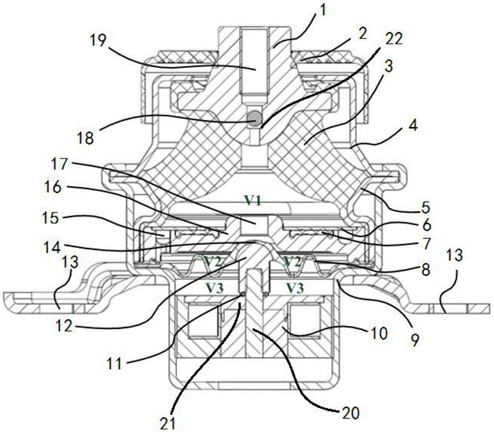
As shown in fig. 1-2, the electronic control flow channel variable semi-active hydraulic suspension of the embodiment includes an inner core 1, a rubber main spring 3 is wrapped around the bottom of the inner core 1, a flow channel cover plate 6 is arranged at the bottom of the rubber main spring 3, a decoupling film 7 is arranged on the lower surface of the flow channel cover plate 6, and an upper liquid chamber V1 is formed in an area enclosed by the lower surface of an inner cavity of the rubber main spring 3, the flow channel cover plate 6 and the upper surface of the decoupling film 7;
a runner plate 16 is arranged below the runner cover plate 6, a short orifice channel 17 is arranged at the central part of the runner plate 16, a bottom diaphragm 8 is arranged at the bottom of the runner plate 16, a lower liquid chamber V2 is formed in an area formed by the lower surface of the runner plate 16 and the upper surface of the bottom diaphragm 8 in a surrounding mode, and the upper liquid chamber V1 is communicated with the lower liquid chamber V2 through the short orifice channel 17;
the periphery of the rubber main spring 3 and the periphery of the bottom diaphragm 8 are provided with mounting brackets 9, and the inner cavity of the bottom of each mounting bracket 9 is provided with an electric control flow channel adjusting mechanism.
The electric control flow channel variable type semi-active hydraulic mount is used as a vibration damping device in vehicle engines, navigation and aviation engines, a decoupling film 7 is arranged on the lower surface of a flow channel cover plate 6, an upper liquid chamber V1 is formed in an area formed by the lower surface of an inner cavity of a rubber main spring 3 and the upper surface of the decoupling film 7, a lower liquid chamber V2 is formed in an area formed by the lower surface of a flow channel plate 16 and the upper surface of a bottom diaphragm 8, the upper liquid chamber V1 is communicated with the lower liquid chamber V2 through a short orifice channel 17, the liquid flow between the upper liquid chamber V1 and the lower liquid chamber V2 is adjusted through an electric control flow channel adjusting mechanism, different liquid flows extrude the decoupling film 7 to generate different rigidity, so that the damping coefficient is changed, the vibration absorption capability of the hydraulic mount is improved, the vibration damping and sound insulation purposes are achieved, and the transfer vibration caused by engine excitation is reduced under various working conditions, meanwhile, the noise reduction effect under the idling working condition and the cruising working condition is improved, and the vibration reduction and noise reduction performance of the hydraulic mount is improved.
The electronic control flow channel adjusting mechanism comprises an electromagnet 10, an electromagnet push rod 20 and a bottom membrane framework 12, wherein the bottom membrane framework 12 is arranged below a short orifice channel 17, the electromagnet push rod 20 penetrates through the axis of the electromagnet 10 and extends upwards, the top end of the electromagnet push rod 20 extends into the bottom membrane framework 12, and a liquid sealing spherical surface 14 is arranged at the top of the bottom membrane framework 12; the electromagnet 10 moves the base film bobbin 12 in the vertical direction by pushing the electromagnet push rod 20.
The upper liquid chamber V1 and the lower liquid chamber V2 are filled with mixed liquid of glycol and water, and the volume ratio of the glycol to the water is 8: 2; the vertical upward movement of the bottom film framework 12 causes the liquid sealing spherical surface 14 to seal the short orifice passage 17, and prevents the mixed liquid in the upper liquid chamber V1 from flowing into the lower liquid chamber V2 through the short orifice passage 17.
An electromagnet cover plate 21 is arranged at the top of the electromagnet 10, and the contact part of the electromagnet cover plate 21 and the electromagnet push rod 20 is sealed by an O-shaped damping ring 11; an air chamber V3 communicated with the atmosphere is formed in an area formed by enclosing the inner wall of the inner cavity at the bottom of the mounting bracket 9, the upper surface of the electromagnet cover plate 21 and the lower surface of the bottom diaphragm 8.
The basement membrane skeleton 12 is connected with the bottom diaphragm 8 through vulcanization, the basement membrane skeleton 12 is connected with the electromagnet 10 through threads, the mounting support 9 is connected with the electromagnet 10 through interference press fitting, and the connection mode is not limited to connection modes such as ultrasonic welding and injection molding.
The runner plate 16 and the runner cover plate 6 are pressed to form a long inertia channel 15, one end of the long inertia channel 15 is communicated with the upper liquid chamber V1, and the other end is communicated with the lower liquid chamber V2. The long inertia track 15 and the short orifice track 17 are independent of each other, and the cross-sectional shapes of the long inertia track 15 and the short orifice track 17 are preferably circular or square, although not limited to other shapes. The ratio of the cross-sectional area a1 of long inertia track 15 to the length L1, a1/L1, is less than the ratio of the cross-sectional area a2 to the length L2 of short orifice track 17. The design of the long inertia channel 15 and the short orifice channel 17 increases the resistance coefficient of the liquid, provides smaller dynamic stiffness in a specific frequency range, improves the vibration absorption capability of the hydraulic suspension, and increases the vibration absorption effect.
The structural design of the electric control flow channel adjusting mechanism ensures that under the cruising working condition of an engine, the electromagnet 10 is electrified, the bottom membrane framework 12 moves upwards, the mixed liquid is sealed by the liquid sealing spherical surface 14, no liquid passes through the short orifice channel 17, and the variable semi-active hydraulic suspension of the electric control flow channel can provide larger damping under the large amplitude and cruising working condition; when the engine is in an idling working condition, small-amplitude middle-high-frequency vibration can be generated due to unbalance of a crankshaft, the electromagnet 10 is not electrified, the bottom membrane framework 12 moves downwards, the liquid sealing spherical surface 14 does not seal mixed liquid, the short orifice channel 17 is opened, the mixed liquid between the upper liquid chamber V1 and the lower liquid chamber V2 flows back and forth between the V1 and the lower liquid chamber V2 through the long inertia channel 15 and the short orifice channel 17, the resistance coefficient is increased, the dynamic characteristic of the variable semi-active hydraulic suspension of the electric control flow channel is changed, small dynamic stiffness with the dynamic-static ratio being less than or equal to 0.8 is generated, the vibration absorption capacity of the variable semi-active hydraulic suspension of the electric control flow channel is improved, and the purposes of vibration absorption and sound insulation are achieved.
A vertical threaded hole 19 is formed in the inner core 1, the threaded hole 19 is connected with an engine support through a bolt, the bottom of the threaded hole 19 is connected with a liquid feeding chamber V1 through a connecting column 22, and a liquid sealing marble 18 is arranged in a cavity of the connecting column 22. The liquid sealing marble 18 can prevent mixed liquid in the upper liquid chamber V1 from entering the threaded hole 19 through the connecting column 22, and the stability of the circulation of the mixed liquid between the upper liquid chamber V1 and the lower liquid chamber V2 is guaranteed.
The periphery of inner core 1 and rubber master spring 3 is equipped with upper cover lid 4, and the top of upper cover lid 4 is located the inner core periphery and is equipped with crashproof pad 2, and the bottom periphery of rubber master spring 3 is equipped with master spring vulcanization skeleton 5, and installing support 9 wraps up the periphery of master spring vulcanization skeleton 5, and the both sides of installing support 9 are stretched out and are had installation bolt hole 13, and installation bolt hole 13 passes through bolt and connected to the frame.
The crash pad 2, the rubber main spring 3, the bottom diaphragm 8, the O-shaped vibration damping ring 11 and the decoupling film 7 in the embodiment are all prepared from natural rubber NR.
As shown in fig. 1 to 4, the working principle of the electric control flow channel variable semi-active hydraulic suspension of the present embodiment includes the following steps:
a. the female terminal of the electromagnet 10 is connected with a special socket of the whole vehicle through a male terminal on a controller, and an engine controls a whole vehicle signal received by a singlechip;
b. under the cruising working condition of the engine, the electromagnet 10 is electrified, the electromagnet 10 pushes the bottom membrane framework 12 to move upwards through the electromagnet push rod 20, the short orifice channel 17 is blocked by the liquid sealing spherical surface 14, the mixed liquid in the upper liquid chamber V1 is prevented from flowing into the lower liquid chamber V2 through the short orifice channel 17, and the variable semi-active hydraulic suspension of the electric control flow channel is ensured to provide larger damping under the large-amplitude cruising working condition;
c. when the engine is in an idling working condition, the small-amplitude middle-high-frequency vibration is generated due to the unbalance of a crankshaft, the electromagnet 10 is powered off, the electromagnet 10 pushes the bottom membrane framework 12 to move downwards through the electromagnet push rod 20, the liquid sealing spherical surface 14 does not seal mixed liquid, the short orifice channel 17 is opened, the mixed liquid between the upper liquid chamber V1 and the lower liquid chamber V2 flows back and forth between the V1 and the lower liquid chamber V2 through the long inertia channel 15 and the short orifice channel 17, the resistance coefficient is increased, the dynamic characteristic of the hydraulic suspension is changed, the dynamic stiffness with the dynamic-static ratio being less than or equal to 0.8 is generated, the vibration absorption capacity of the electric control flow channel variable type semi-active hydraulic suspension is improved, the purposes of vibration absorption and sound insulation are achieved, and the active hydraulic suspension can generate two notch frequency sections and two peak frequency sections to isolate various unbalanced excitations.
It is noted that, in this document, relational terms such as first and second, and the like, if any, are used solely to distinguish one entity or action from another entity or action without necessarily requiring or implying any actual such relationship or order between such entities or actions. Also, the terms "comprises," "comprising," or any other variation thereof, are intended to cover a non-exclusive inclusion, such that a process, method, article, or apparatus that comprises a list of elements does not include only those elements but may include other elements not expressly listed or inherent to such process, method, article, or apparatus. Without further limitation, an element defined by the phrase "comprising an … …" does not exclude the presence of other identical elements in a process, method, article, or apparatus that comprises the element.
The above embodiments are only used to illustrate the technical solution of the present invention, and not to limit it; although the present invention has been described in detail with reference to the foregoing embodiments, it should be understood by those skilled in the art that: the technical solutions described in the foregoing embodiments may still be modified, or some technical features may be equivalently replaced; such modifications and substitutions do not depart from the spirit and scope of the present invention in its corresponding aspects.