Automatic collecting device of fibre cloth limit waste material
Technical Field
The utility model relates to a collection device especially relates to an automatic collection device of fibre cloth limit waste material.
Background
The fiber cloth can produce raw material waste in the production process, and the existing collection method for the raw material waste in the fiber cloth production process comprises the following two methods: firstly, manual collection, namely arranging two persons to manually take off the scrap materials cut off by the production line and put the scrap materials into a waste box at two sides of a fiber cloth production machine; the method has the disadvantages of high labor cost and high labor intensity; secondly, the material edge waste is collected by adopting the existing collecting mechanism with a simpler structure, and the method has the defects that the speed of collecting the material edge of the existing collecting device is constant, and the collecting speed cannot automatically compensate and feed along with the production change, so that the speed of collecting the material edge waste cannot be automatically consistent with the production speed; and the existing collecting device is difficult to adjust when the fiber cloth production machine produces products with different widths, and the adaptability adjustment can not be well carried out so as to collect the material edge waste materials generated when the fiber cloth production machine produces different width products.
SUMMERY OF THE UTILITY MODEL
In order to solve the defects of the prior art, the utility model provides an automatic collecting device for fiber cloth edge waste.
In order to solve the technical problem, the utility model discloses a technical scheme is: an automatic collecting device for fiber cloth edge waste comprises a rack, wherein a motor and a collecting mechanism are arranged on the rack, and the motor is fixed at the front part of the rack; the output end of the motor is connected with a driving shaft, the number of the collecting mechanisms is two, the two collecting mechanisms are symmetrically arranged, and the two collecting mechanisms are connected through the driving shaft;
the collecting mechanism comprises a driving mechanism, a driven mechanism, a moving mechanism and a winding mechanism, wherein the driving mechanism comprises a driving wheel and a driving shaft, and the driving wheel is arranged on the driving shaft through a friction clutch; the driven mechanism comprises a driven wheel and a driven shaft, the driven wheel is fixedly sleeved on one end of the driven shaft, and the driven wheel is connected with the driving wheel through a transmission belt; the other end of the driven shaft is connected with an output shaft through a coupling A, and the winding mechanism is fixedly arranged at the other end of the output shaft; the moving mechanism is matched with the output shaft and is positioned below the output shaft.
Furthermore, the friction clutch comprises a clutch body which is fixedly sleeved on the driving shaft; a clutch friction plate, a check washer and a nut are sequentially sleeved on the clutch body from the head end to the tail end; the clutch friction plates are two, and the driving wheel is rotatably sleeved on the clutch body and is positioned between the two clutch friction plates.
The moving mechanism comprises a slide rail and a slide block, the slide block and the slide rail are arranged in a sliding fit manner, and the slide rail is transversely arranged on the rack; a support table is fixedly arranged on the sliding block; bearings are arranged at two ends of the output shaft, the bearings are arranged in bearing seats, and the bearing seats are fixedly arranged on the supporting table; and a locking mechanism which can be matched and locked with the rack is arranged on the sliding block.
The first coupler body is fixedly sleeved at the end part of the output shaft, and the second coupler body is fixedly sleeved at the end part of the driven shaft; the guide shaft is fixedly arranged on one side of the first coupler body, and the second coupler body is slidably sleeved on the guide shaft.
Furthermore, the anti-loosening gasket is provided with a bending piece.
Furthermore, the output end of the motor is connected with the driving shaft through a coupling B.
Furthermore, the driving wheel is a triangular belt wheel.
Furthermore, four guide shafts are arranged and are respectively fixedly connected with the first coupling body through hexagon socket head cap screws.
The automatic collecting device of the utility model is provided with the friction clutch, the edge collecting speed of the collecting device can be automatically adjusted, the edge collecting speed can automatically compensate and feed along with the production change of the fiber cloth production machine, and thus the speed of collecting the waste materials at the edge of the material is automatically consistent with the production speed; the cooperation setting of shaft coupling A and moving mechanism can freely adjust the receipts limit width of collection device, and the adjustment is simple and convenient when the different broad width products of fibre cloth production machine production, can carry out the adaptability adjustment well in order to be competent in collecting the material limit waste material that produces when the different broad width products of fibre cloth production machine production, has strengthened automatic collection device's suitability and practicality greatly, has improved the effect of collecting of material limit waste material.
Drawings
Fig. 1 is a schematic view of the position relationship when the waste material collecting range of the automatic collecting device of the present invention is in the minimum range.
Fig. 2 is a top view of fig. 1.
Fig. 3 is a schematic diagram of the position relationship of the automatic collecting device when the waste material collecting range is in the maximum range.
Fig. 4 is a top view of fig. 3.
Fig. 5 is a left side view of fig. 1.
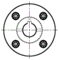
Fig. 6 is a side view of the coupling a.
Fig. 7 is a schematic diagram of the position relationship of the coupling a in fig. 1.
Fig. 8 is a schematic diagram of the position relationship of the coupling a in fig. 3.
FIG. 9 is a side view of the friction clutch.
Fig. 10 is a sectional view taken along line a-a of fig. 9.
In the figure: 1. a frame; 2. a motor; 3. a drive shaft; 4. a coupler B; 5. a driving wheel; 6. a friction clutch; 7. a coupler A; 8. a driven wheel; 9. a driven shaft; 10. a transmission belt; 11. an output shaft; 12. A winding mechanism; 13. a slide rail; 14. a slider; 15. a support table; 16. a bearing seat;
61. a clutch body; 62. a clutch friction plate; 63. a lock washer; 64. a nut; 65. bending the sheet;
71. a first shaft coupling body; 72. a second coupler body; 73. a guide shaft; 74. a hexagon socket head cap screw.
Detailed Description
The present invention will be described in further detail with reference to the accompanying drawings and specific embodiments.
As shown in fig. 1, an automatic collecting device for fiber cloth edge waste comprises a frame 1, wherein a motor 2 and a collecting mechanism are arranged on the frame 1, and the motor 2 is fixed at the front part of the frame; the output end of the motor 2 is connected with a driving shaft 3, and the driving shaft are connected through a coupler B4. The two collecting mechanisms are symmetrically arranged and connected through a driving shaft 3;
the collecting mechanism comprises a driving mechanism, a driven mechanism, a moving mechanism and a winding mechanism 12, the driving mechanism comprises a driving wheel 5 and a driving shaft 3, and the driving wheel 5 is arranged on the driving shaft 3 through a friction clutch 6; as shown in fig. 9 and 10, the friction clutch 6 includes a clutch body 61, and the clutch body 61 is fixedly sleeved on the driving shaft 3; a clutch friction plate 62, a check washer 63 and a nut 64 are sequentially sleeved on the clutch body 61 from the head end to the tail end; the clutch friction plates 62 are two pieces, and the driving wheel 5 is rotatably sleeved on the clutch body 61 and located between the two clutch friction plates. The anti-loosening gasket 63 is provided with a bending piece 65. The friction force of the clutch friction plate to the driving wheel is adjusted through the adjusting nut 64; when the friction force is adjusted, the bending piece 65 of the anti-loosening gasket is bent to ensure that the nut 64 cannot be loosened.
The driven mechanism comprises a driven wheel 8 and a driven shaft 9, the driven wheel 8 is fixedly sleeved on one end of the driven shaft 9, and the driven wheel 8 is connected with the driving wheel 5 through a transmission belt 10; the driving wheel 5 can be a triangular belt wheel.
The other end of the driven shaft 9 is connected with an output shaft 11 through a coupler A7, and a winding mechanism 12 is fixedly arranged on the other end of the output shaft 11.
As shown in fig. 7 and 8, the coupling a7 includes a first coupling body 71, a second coupling body 72, and a guide shaft 73, wherein the first coupling body 71 is fixedly sleeved on the end of the output shaft 11, and the second coupling body 72 is fixedly sleeved on the end of the driven shaft 9; the guide shaft 73 is fixedly arranged on one side of the first coupling body 71, and the second coupling body 72 is slidably sleeved on the guide shaft 73. Four guide shafts 73 are fixedly connected with the first coupling body 71 through hexagon socket screws 74, and the torque transmission effect of the coupling A is better due to the arrangement of the four guide shafts.
The moving mechanism is arranged in a matching way with the output shaft 11, and the moving mechanism is positioned below the output shaft 11. The moving mechanism comprises a slide rail 13 and a slide block 14, the slide block 14 is arranged in a sliding fit with the slide rail 13, and the slide rail 13 is transversely arranged on the rack 1; a support table 15 is fixedly arranged on the slide block 14; bearings are arranged at two ends of the output shaft 11, the bearings are arranged in bearing seats 16, and the bearing seats 16 are fixedly arranged on the supporting platform 15; the slide block 14 is provided with a locking mechanism which can be matched and locked with the frame 1.
As shown in fig. 1 and 3, when the fiber cloth production machine is producing products with different widths, the range of the automatic collecting device for collecting the waste materials at the material collecting side is adjusted by adjusting the shaft coupling a and the moving mechanism; when the adjusting is carried out, the locking mechanism is loosened, and the locking mechanism can move relative to the rack along with the sliding block; the output shaft is pulled to adjust the position of the winding mechanism 12, the output shaft 11 moves to drive the first coupler body to move, the first coupler body drives the guide shaft to move relative to the second coupler body, meanwhile, the output shaft moves to drive the bearing blocks at the two ends of the output shaft to move, the bearing blocks move to drive the supporting table fixed below the bearing blocks to move, and the supporting table drives the sliding block to slide on the sliding rail; the moving mechanism is matched with the output shaft 11, so that when the locking mechanism is loosened, the moving output shaft can realize stepless adjustment of the range of collecting the waste materials while the materials are collected from the minimum range to the maximum range; locking mechanism when the scope regulation of material limit waste material reaches the requirement, locking mechanism of locking locks the slider for the position of frame, and the slider that is locked can't continue to slide along the slide rail, and then through brace table, bearing frame locking output shaft's position to locking winding mechanism makes winding mechanism can accomplish in the task of drawing the limit of the different broad width product productions of fibre cloth production machine for the position of automatic collection device's frame, has improved greatly the utility model discloses an automatic collection device's suitability and practicality.
The utility model discloses an automatic collect device during operation, the motor drives the driving shaft and rotates, and the driving shaft passes through friction clutch and drives the action wheel and rotate, and the action wheel passes through the drive belt and drives from the driving wheel rotation, drives the driven shaft rotation from the driving wheel, and the driven shaft passes through shaft coupling A and drives the output shaft rotation, and then drives winding mechanism and rotate and collect the material limit waste material that produces in the fibre cloth production machine production process.
Because the friction clutch is arranged on the driving shaft of the automatic collecting device, when the collecting speed of the automatic collecting device for collecting the material edge waste is greater than the production line production speed of the fiber cloth production machine, the external force applied by the material edge waste received when the winding mechanism collects the edge is greater, the force transmitted to the driving wheel by the winding mechanism is greater, the force is greater than the maximum static friction force between the clutch friction plate and the driving wheel, the friction clutch begins to slip, and the collecting edge of the winding mechanism is temporarily slowed down; when the friction clutch slips, the driving wheel and the friction clutch slide relatively, the sliding friction force between the driving wheel and the friction clutch reduces the speed of the driving wheel, the difference value between the edge folding speed of the winding mechanism and the production speed of the fiber cloth production machine is smaller and smaller along with the reduction of the rotating speed of the driving wheel, the external force exerted on the winding mechanism by the material edge waste is also reduced, the force transmitted to the driving wheel by the winding mechanism is also reduced along with the reduction of the external force, when the force is less than or equal to the maximum static friction force between the friction plate of the clutch and the driving wheel, the friction clutch recovers to work normally and does not slip any more, the edge folding speed of the winding mechanism of the automatic take-up device is consistent with the production speed of the fiber cloth production machine, the automatic compensation feeding of the edge folding speed of the winding mechanism along with the production change is realized, this has strengthened automatic harvesting device's suitability and practicality greatly, has improved the effect of collecting of material limit waste material.
The above embodiments are not intended to limit the present invention, and the present invention is not limited to the above examples, and the technical personnel in the technical field are in the present invention, which can also belong to the protection scope of the present invention.