Rectifying column for chemical production
Technical Field
The utility model relates to a chemical production technical field specifically is a rectifying column for chemical production.
Background
The rectifying tower is a tower type vapor-liquid contact device for rectification, and utilizes the property that each component in a mixture has different volatility, namely the vapor pressure of each component is different at the same temperature, so that light components (low-boiling-point substances) in a liquid phase are transferred into a gas phase, and heavy components (high-boiling-point substances) in the gas phase are transferred into the liquid phase, thereby realizing the purpose of separation.
The existing rectifying tower has the following defects:
1. after the rectifying tower is used for a long time, the inner wall of the rectifying tower is easy to scale, and the existing rectifying tower is inconvenient to clean the inner wall of the rectifying tower;
2. the sewage after the inner wall of the rectifying tower for chemical production is cleaned has a plurality of chemical components, and is directly discharged to easily pollute a water source.
SUMMERY OF THE UTILITY MODEL
Technical problem to be solved
The utility model provides a not enough to prior art, the utility model provides a rectifying column for chemical production has solved current rectifying column for chemical production and has been not convenient for wash the problem that pollutes the water source easily with the sewage direct discharge after wasing the tower inner wall.
(II) technical scheme
In order to achieve the above object, the utility model provides a following technical scheme: a rectifying tower for chemical production comprises a tower body, wherein the top of the tower body is communicated with a first connecting pipe, the bottom of the tower body is fixedly connected with a supporting leg, the side wall of the tower body is communicated with a second connecting pipe, a water tank is installed on the side wall of the tower body, a water pump is arranged on the side wall of the tower body, the top of the water tank is communicated with a water inlet at the bottom of the water pump through a pipe, a motor is arranged at the bottom of the tower body, an inner bottom wall of the tower body is rotatably connected with a vertical pipe, an output shaft of the motor penetrates through the bottom of the tower body and is fixedly connected with the lower end of the vertical pipe, a bearing is rotatably connected to the surface of the vertical pipe, an L-shaped pipe is rotatably connected to the inner wall of the bearing, one end of the L-shaped pipe penetrates through and extends out of the tower body, a conveying pipe is fixedly connected to the end of the L-shaped pipe, the lower end of the conveying pipe is communicated with a water outlet hole at the top of the water pump, two L-shaped rods which are symmetrically distributed are fixedly connected to the surface of the vertical pipe, one side fixedly connected with brush of L shape pole, one side of L shape pole is provided with the shower nozzle, the opposite side intercommunication of L shape pole has violently the pipe, the lateral wall intercommunication of tower body has the drain pipe, the bottom intercommunication of drain pipe has the rose box, the surface of drain pipe is provided with sealing valve.
As a preferred technical scheme of the utility model, one side of rose box sets up to the opening, the inner wall of rose box is pegged graft and is had the rectangle case, one side fixedly connected with L shape inserted bar of rectangle case, the slot has been seted up to one side of rose box, the jack has all been seted up at the top of rose box and L shape inserted bar, the top of rose box is pegged graft and is had the U-shaped pole.
As a preferred technical scheme of the utility model, the inner wall of rectangle case is seted up flutedly, the interior roof fixedly connected with montant of recess, the surface sliding of montant is connected with the filter screen, the bottom butt of filter screen has the activated carbon plate.
As an optimized technical scheme of the utility model, one side intercommunication of rose box has the blow off pipe, the through-hole has been seted up on the surface of rectangle case.
As an optimized technical scheme of the utility model, the upper surface of rectangle case is provided with sealed the pad.
As an optimized technical scheme of the utility model, the surface of first connecting pipe and second connecting pipe all is provided with check valve.
(III) advantageous effects
Compared with the prior art, the utility model provides a rectifying column for chemical production possesses following beneficial effect:
1. this rectifying column for chemical production, water tank through setting up, a water pump, including a motor, an end cap, a controller, and a cover plate, standpipe and brush cooperate, the setting of water pump can be taken out the water in the water tank and carry to L shape intraductally, hydroenergy can flow in the inside of standpipe along the L venturi tube, the lateral wall intercommunication of standpipe has violently the pipe, hydroenergy can flow to the tip of violently managing, and supply water for the shower nozzle, under the effect of bearing, the motor can drive the standpipe and rotate, the standpipe can drive the brush when rotating and rotate, the brush distributes between the shower nozzle, can wash the inner wall of tower when rotating, be convenient for wash the inner wall of rectifying column from this, and convenient for operation, can guarantee the precision of production product, can prolong the life of rectifying column simultaneously.
2. This rectifying column for chemical production cooperatees through rose box, rectangle case, filter screen and the activated carbon board that sets up, and wherein the filter screen can filter the large granule impurity that emits into in the rose box, and the peculiar smell in the active carbon can adsorb sewage, can tentatively handle discharged sewage from this, avoids sewage direct discharge sewer pipe, corrodes or blocks up sewer pipe.
Drawings
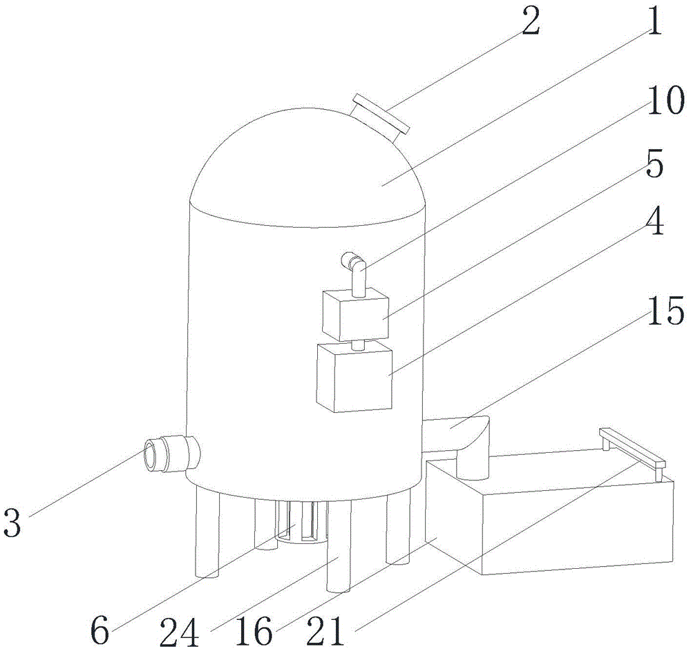
FIG. 1 is a schematic structural view of the present invention;
fig. 2 is a sectional view of the present invention;
FIG. 3 is an enlarged view of the point A in FIG. 2 according to the present invention;
FIG. 4 is a schematic view of the connection structure of the filtering box and the rectangular box of the present invention;
fig. 5 is a schematic diagram of the internal structure of the rectangular box of the present invention.
In the figure: 1. a tower body; 2. a first connecting pipe; 3. a second connecting pipe; 4. a water tank; 5. a water pump; 6. a motor; 7. a vertical tube; 8. a bearing; 9. an L-shaped tube; 10. a delivery pipe; 11. an L-shaped rod; 12. a brush; 13. a spray head; 14. a transverse tube; 15. a drain pipe; 16. a filter box; 17. a rectangular box; 18. a vertical rod; 19. a filter screen; 20. an L-shaped insert rod; 21. a U-shaped rod; 22. a blow-off pipe; 23. an activated carbon plate; 24. and (5) supporting legs.
Detailed Description
The technical solutions in the embodiments of the present invention will be described clearly and completely with reference to the accompanying drawings in the embodiments of the present invention, and it is obvious that the described embodiments are only some embodiments of the present invention, not all embodiments. Based on the embodiments in the present invention, all other embodiments obtained by a person skilled in the art without creative work belong to the protection scope of the present invention.
Examples
Referring to fig. 1-5, the present invention provides the following technical solutions: a rectifying tower for chemical production comprises a tower body 1, the top of the tower body 1 is communicated with a first connecting pipe 2, the bottom of the tower body 1 is fixedly connected with a supporting leg 24, the side wall of the tower body 1 is communicated with a second connecting pipe 3, the side wall of the tower body 1 is provided with a water tank 4, the side wall of the tower body 1 is provided with a water pump 5, the top of the water tank 4 is communicated with a water inlet at the bottom of the water pump 5 through a guide pipe, the bottom of the tower body 1 is provided with a motor 6, the inner bottom wall of the tower body 1 is rotatably connected with a vertical pipe 7, an output shaft of the motor 6 penetrates through the bottom of the tower body 1 and is fixedly connected with the lower end of the vertical pipe 7, the surface of the vertical pipe 7 is rotatably connected with a bearing 8, the inner wall of the bearing 8 is rotatably connected with an L-shaped pipe 9, one end of the L-shaped pipe 9 penetrates through and extends out of the tower body 1, the end part of the L-shaped pipe 9 is fixedly connected with a conveying pipe 10, the lower end of the conveying pipe is communicated with a water outlet hole at the top of the water pump 5, the surface of the vertical pipe 7 is fixedly connected with two L-shaped rods 11 which are symmetrically distributed, one side of each L-shaped rod 11 is fixedly connected with a brush 12, one side of each L-shaped rod 11 is provided with a spray head 13, the other side of each L-shaped rod 11 is communicated with a transverse pipe 14, the side wall of the tower body 1 is communicated with a drain pipe 15, the bottom of each drain pipe 15 is communicated with a filter box 16, and the surface of each drain pipe 15 is provided with a sealing valve.
In this embodiment, the water source can be stored in the setting of water tank 4, the setting of water pump 5 can take the water in the water tank 4 out and carry to the L venturi tube 9 in, the rotation of standpipe 7 can be realized in the setting of bearing 8, the setting of conveyer pipe 10 can communicate L venturi tube 9 and water pump 5, shower nozzle 13 is provided with a plurality ofly, and evenly distributed is between brush 12, shower nozzle 13's setting can be towards the inner wall of tower water spray or spray chemical liquid, the scale removal of being convenient for, the inner wall of the brush tower is convenient for to sweep in the setting of brush 12, make the cleaning performance better, drain pipe 15 set up can be with the sewage after the washing discharge to the rose box 16 in the rectifying column, sealing valve's the discharge of being convenient for control sewage of establishing.
Specifically, one side of filter box 16 sets up to the opening, and the inner wall of filter box 16 is pegged graft and is had rectangle case 17, and one side fixedly connected with L shape inserted bar 20 of rectangle case 17, the slot has been seted up to one side of filter box 16, and the jack has all been seted up at the top of filter box 16 and L shape inserted bar 20, and the top of filter box 16 is pegged graft and is had U-shaped pole 21.
In this embodiment, the rectangular box 17 is convenient for take out the large granule impurity that is arranged into in the rose box 16, is convenient for change filter screen 19 and active carbon board 23 simultaneously, and L shape inserted bar 20 can insert in the slot that rose box 16 one side was seted up, and the jack that the top of filter box 16 and L shape inserted bar 20 was seted up can be run through to U-shaped pole 21, from the position that can fix rectangular box 17.
Specifically, the inner wall of rectangle case 17 is seted up flutedly, and the interior roof fixedly connected with montant 18 of recess, the surperficial sliding connection of montant 18 have a filter screen 19, and the bottom butt of filter screen 19 has activated carbon plate 23.
In this embodiment, the vertical rod 18 is convenient for fixing the positions of the filter screen 19 and the activated carbon plate 23, and is convenient for taking out the filter screen 19 and the activated carbon plate 23 for cleaning or replacement.
Specifically, one side of the filter box 16 is communicated with a sewage discharge pipe 22, and the surface of the rectangular box 17 is provided with a through hole.
In this embodiment, the sewage drain pipe 22 is provided so that sewage in the filter tank 16 can be drained.
Specifically, the upper surface of the rectangular tank 17 is provided with a gasket.
In this embodiment, the provision of the gasket can prevent water leakage.
Specifically, the surfaces of the first connecting pipe 2 and the second connecting pipe 3 are both provided with one-way valves.
In this embodiment, the setting of check valve is convenient for control feeding and ejection of compact.
The utility model discloses a theory of operation and use flow: after the rectifying tower is used for a period of time, the inner wall of the rectifying tower can be condensed with a large amount of dirt, the inner wall of the rectifying tower needs to be cleaned, at the moment, a switch of a water pump 5 is turned on, the water pump 5 can pump out water or chemical liquid in a water tank 4 and convey the water into an L-shaped pipe 9, the water can flow into the interior of a vertical pipe 7 along the L-shaped pipe 9, the side wall of the vertical pipe 7 is communicated with a transverse pipe 14, the water can flow to the end part of the transverse pipe 14 and supply water to a spray head 13, at the moment, a motor 6 is started, the motor 6 can drive the vertical pipe 7 to rotate under the action of a bearing 8, the vertical pipe 7 can drive a brush 12 to rotate when rotating, as a plurality of spray heads 13 are arranged between the brushes 12, the inner wall of the tower can be cleaned when rotating, therefore, the inner wall of the rectifying tower is convenient to clean, the operation can ensure the precision of product production, meanwhile, the service life of the rectifying tower can be prolonged, the cleaned sewage can be discharged from a drain pipe 15 and enter a filter tank 16, large granule impurity in the sewage is at first filtered by filter screen 19, activated carbon plate 23 can adsorb the peculiar smell in the sewage, and then, sewage can be by preliminary treatment between the discharge entering sewer pipe, harmful smell and large granule impurity in the sewage have been reduced, avoid blockking up and corrode sewer pipe, when needs wash or change filter screen 19 and activated carbon plate 23 to rectangle case 17 in, upwards stimulate U-shaped pole 21 and make U-shaped pole 21 and jack separation, can take rectangle case 17 out outside rose box 16, slide filter screen 19 and activated carbon plate 23 along montant 18's surface from top to bottom in proper order, can take out filter screen 19 and activated carbon plate 23 and wash or change.
Finally, it should be noted that: although the present invention has been described in detail with reference to the foregoing embodiments, it will be apparent to those skilled in the art that modifications may be made to the embodiments described in the foregoing embodiments, or equivalents may be substituted for elements thereof. Any modification, equivalent replacement, or improvement made within the spirit and principle of the present invention should be included in the protection scope of the present invention.