SUMMERY OF THE UTILITY MODEL
The utility model provides a to prior art not enough, provide a supplementary device of changing dressings for ordinary surgery nursing, solved present patient that need change dressings to low limbs effectively and raised the problem of unstable, the easy contaminated bed clothes of back location of suffering from the limb that exists when changing dressings.
In order to solve the above problems, the utility model adopts the following technical proposal:
an auxiliary dressing change device for general surgical nursing comprises a base with universal wheels, wherein a seat plate is arranged at the top of the base, a backup plate capable of adjusting a front and back inclination angle is arranged at the rear side of the seat plate, and a left leg lifting plate and a right leg lifting plate capable of adjusting the front and back inclination angle are arranged at the front side of the seat plate; the tail end of the leg lifting plate is respectively provided with an adjusting plate capable of adjusting the relative position of the leg lifting plate and the leg lifting plate; the front sides of the adjusting plates are respectively provided with a front lifting plate capable of adjusting the front and rear positions; a rear lifting plate capable of adjusting the front and rear positions is arranged on the front side of the head end of the leg lifting plate; two bandages on the left and right are arranged on the front side of the front lifting plate.
Preferably, the head end of the leg lifting plate is hinged to the front side of the seat plate; the middle part of the rear side of the leg lifting plate is respectively provided with an extension rod, and the tail ends of the extension rods are respectively hinged with a leg lifting support rod;
the left side and the right side of the base are respectively and rotatably connected with a leg lifting screw rod, the leg lifting screw rods are respectively in threaded connection with leg lifting screw blocks, the left side and the right side of each leg lifting screw block are respectively and slidably connected with leg lifting slide rods, and the leg lifting slide rods are fixedly connected with the base; the rear ends of the leg lifting screw rods are respectively and fixedly connected with leg lifting wheels; the leg lifting support rods are respectively hinged to the tops of the leg lifting screw blocks at corresponding positions.
Preferably, a rotating shaft is arranged at the bottom of the backup plate, and the backup plate is hinged with the seat plate through the rotating shaft; the rotating shaft is coaxially and fixedly connected with an angle worm gear; the side end of the seat plate is rotatably connected with an angle worm, and the angle worm is meshed with the angle worm wheel; the rear end of the angle worm is coaxially and fixedly connected with an angle wheel.
Preferably, a guide plate is arranged at the top of the adjusting plate and is connected in the leg lifting plate in a sliding manner; and a locking screw is in threaded connection with the rear side of the tail end of the leg lifting plate and the front side of the tail end of the leg lifting plate, and the locking screw is screwed to form a structure with fixed positions of the adjusting plate and the leg lifting plate.
Preferably, the right side of the front end of the adjusting plate is hinged with a right support rod; the left side of the front end of the adjusting plate is slidably connected with a bottom sliding plate capable of moving left and right; the front end of the bottom sliding plate is hinged with a left stay bar; the tail end of the left support rod is hinged to the right side of the rear end of the front lifting plate;
the left side of the rear end of the front lifting plate is slidably connected with a top sliding plate capable of moving left and right, and the tail end of the right stay bar is hinged with the top sliding plate; the middle parts of the left stay bar and the right stay bar are hinged with each other;
the middle part of the bottom sliding plate is connected with a positioning screw in a backward threaded manner; a plurality of positioning holes are formed in the front end of the adjusting plate from left to right; and the positioning screw is screwed into any positioning hole to form a structure for fixing the positions of the bottom sliding plate and the adjusting plate.
Preferably, the rear side of the upper part of the leg lifting plate is rotatably connected with a bidirectional screw, and the screw threads on the left side and the right side of the bidirectional screw are opposite in rotation direction; the bidirectional screw rod is coaxially and fixedly connected with a supporting wheel; the left side and the right side of the bidirectional screw are respectively in threaded connection with a right screw block and a left screw block; the bottoms of the left screw block and the right screw block are both connected with limiting rods in a sliding manner; the limiting rod is fixedly connected with the leg lifting plate;
the left screw block front side is hinged with a left swing rod, the right screw block front side is hinged with a right swing rod, the tail end of the left swing rod is hinged to the left side of the rear end of the rear lifting plate, and the tail end of the right swing rod is hinged to the right side of the rear end of the rear lifting plate.
Preferably, the head ends of the binding bands are respectively and fixedly connected to the left side and the right side of the front lifting plate; the left bandage tail end fixedly connected with is the connector link of day font, and the right side bandage tail end outside has set gradually thorn face magic subsides and hair side magic subsides along length direction.
The utility model discloses novel structure, think about ingenious, easy operation is convenient, compares with prior art and has following advantage:
1. this device is through setting up about two adjustable front and back swing angle lift the leg board to set up adjustable front and back and vertical position's preceding liter board on it, the back of adjustable front and back position rises the board, thereby can raise patient's affected limb and lift the separation of leg board (keep out the space of changing dressings), and then can be convenient for medical personnel to change dressings the operation, reduced the operation degree of difficulty effectively, improved operator's the efficiency of changing dressings.
2. This device is through setting up backup plate, the base that can freely remove at adjustable inclination, cooperates the leg raising version of adjustable front and back pivot angle to can remove this device to suitable position, be convenient for change dressings to the patient, improve the rate of adaptation of changing dressings of this device effectively, reduce the degree of difficulty of operation, and can reduce patient's misery and uncomfortable and feel.
Drawings
Fig. 1 is a first axis mapping diagram of an auxiliary dressing change device for general surgical nursing of the utility model.
Fig. 2 is a second axial view of the auxiliary dressing change device for general surgical nursing of the present invention.
Fig. 3 is an axonometric view of the base of the auxiliary dressing change device for general surgical nursing and the upper part thereof.
Fig. 4 is an axonometric view of the seat plate and its backup plate of the auxiliary dressing change device for general surgical nursing of the present invention.
Fig. 5 is a first perspective view of a leg-lifting plate of an auxiliary dressing change device for general surgical nursing according to the present invention.
Fig. 6 is a second axial view of the leg lifting plate of the auxiliary dressing change device for general surgical nursing of the present invention.
Fig. 7 is a first perspective view of a front lifting plate of an auxiliary dressing change device for general surgical nursing according to the present invention.
Fig. 8 is a second axial view of the front lifting plate of the auxiliary dressing change device for general surgical nursing according to the present invention.
Fig. 9 is an isometric view of a rear lifting plate of the auxiliary dressing change device for general surgical nursing of the present invention.
In the drawings: 1-base, 2-universal wheel, 3-base plate, 4-backing plate, 5-leg lifting plate, 6-adjusting plate, 7-rear lifting plate, 8-front lifting plate, 9-binding band, 10-leg lifting screw, 11-leg lifting slide rod, 12-leg lifting wheel, 13-leg lifting screw block, 14-leg lifting support rod, 15-rotating shaft, 16-angle worm wheel, 17-angle worm, 18-angle wheel, 19-connecting buckle, 20-locking screw, 21-guide plate, 22-extension rod, 23-left support rod, 24-right support rod, 25-top sliding plate, 26-bottom sliding plate, 27-positioning screw, 28-positioning hole, 29-left swinging rod, 30-right swinging rod, 31-left screw block, 32-right screw block, 24-left screw block, 33-a bidirectional screw, 34-a limiting rod and 35-a supporting wheel.
Detailed Description
The following are specific embodiments of the present invention, and the technical solutions of the present invention will be further described with reference to the accompanying drawings, but the present invention is not limited to these embodiments.
As shown in fig. 1-9, the utility model provides an auxiliary dressing change device for general surgical nursing, which comprises a base 1 with universal wheels 2, a seat plate 3 is arranged on the top of the base 1, a back plate 4 with adjustable front and back inclination angles is arranged on the rear side of the seat plate 3, and two leg lifting plates 5 with adjustable front and back inclination angles are arranged on the front side of the seat plate 3; the tail end of the leg lifting plate 5 is respectively provided with an adjusting plate 6 which can adjust the relative position of the leg lifting plate 5; the front sides of the adjusting plates 6 are respectively provided with a front lifting plate 8 with adjustable front and back positions; a rear lifting plate 7 with adjustable front and rear positions is arranged on the front side of the head end of the leg lifting plate 5; the front side of the front lifting plate 8 is provided with a left binding band and a right binding band 9.
This device is through setting up about two adjustable front and back swing angles lift leg board 5 to set up adjustable front and back and the preceding board 8 that rises of vertical position on it, the back board 7 that rises of position around adjustable, thereby can raise patient's affected limb and lift leg board 5 separation (keep out the space of changing dressings), and then can be convenient for medical personnel to change dressings the operation, reduced the operation degree of difficulty effectively, improved operator's the efficiency of changing dressings.
This device is through setting up backup plate 4, the base 1 that can freely remove at adjustable inclination, cooperates the leg raising version 5 of adjustable front and back pivot angle to can remove this device to suitable position, be convenient for change dressings to the patient, improve the rate of adaptation of changing dressings of this device effectively, reduce the degree of difficulty of operation, and can reduce patient's misery and uncomfortable sense.
As shown in fig. 1, 2, 3 and 5, the head end of the leg raising plate 5 is hinged to the front side of the seat plate 3; the middle part of the rear side of the leg lifting plate 5 is respectively provided with an extension rod 22, and the tail ends of the extension rods 22 are respectively hinged with a leg lifting brace 14;
the left side and the right side of the base 1 are respectively and rotatably connected with a leg lifting screw rod 10, the leg lifting screw rods 10 are respectively in threaded connection with leg lifting screw blocks 13, the left side and the right side of each leg lifting screw block 13 are respectively and slidably connected with leg lifting slide rods 11, and the leg lifting slide rods 11 are all fixedly connected with the base 1; the rear ends of the leg lifting screw rods 10 are respectively and fixedly connected with leg lifting wheels 12; the leg lifting support rods 14 are respectively hinged to the tops of the leg lifting screw blocks 13 at corresponding positions.
The affected limb which needs to be changed is the left lower limb or the right lower limb, so that the leg lifting plates 5 at different positions are lifted, and the medicine changing operation is convenient.
The principle of the adjustment of the inclination angle of the leg raising plate 5 is as follows:
the leg lifting wheel 12 is rotated, so that the leg lifting screw rod 10 rotates, the leg lifting screw rod 10 drives the leg lifting screw block 13 in threaded connection with the leg lifting screw rod to move back and forth along the axial direction of the leg lifting slide rod 11, the leg lifting stay bar 14 swings, the leg lifting stay bar 14 drives the leg lifting plate 5 connected with the leg lifting stay bar 14 to rotate around the hinge shaft of the leg lifting plate 5 and the seat plate 3, the inclination angle adjustment is realized, and the affected limb of a patient is conveniently lifted.
As shown in fig. 4, a rotating shaft 15 is arranged at the bottom of the backup plate 4, and the backup plate 4 is hinged with the seat plate 3 through the rotating shaft 15; the rotating shaft 15 is coaxially and fixedly connected with an angle worm wheel 16; an angle worm 17 is rotatably connected to the side end of the seat plate 3, and the angle worm 17 is meshed with the angle worm wheel 16; the rear end of the angle worm 17 is coaxially and fixedly connected with an angle wheel 18.
When the affected limb need be raised to the patient, medical personnel can adjust backup plate 4 to suitable inclination, and the patient of being convenient for semi-lies the posture for the patient comfort level improves when changing dressings.
The angle wheel 18 is rotated, so that the angle worm 17 rotates, the angle worm 17 drives the angle worm wheel 16 in meshed connection with the angle worm 17 to rotate, and then the angle worm wheel 16 can drive the backup plate 4 fixed with the angle worm wheel to rotate around the axial direction of the rotating shaft 15, and the inclination angle adjustment of the backup plate 4 is realized.
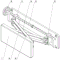
As shown in fig. 5-6, a guide plate 21 is arranged on the top of the adjusting plate 6, and the guide plate 21 is slidably connected in the leg raising plate 5; the rear side of the tail end of the leg lifting plate 5 is connected with a locking screw 20 in a threaded mode, and the locking screw 20 is screwed to form a structure with fixed positions of the adjusting plate 6 and the leg lifting plate 5.
The distance between the adjusting plate 6 and the leg lifting plate 5 is adjusted according to the leg length of the patient, and the locking screw 20 is screwed to realize positioning.
As shown in fig. 7-8, a right support rod 24 is hinged to the right side of the front end of the adjusting plate 6; a bottom sliding plate 26 capable of moving left and right is connected to the left side of the front end of the adjusting plate 6 in a sliding manner; the front end of the bottom sliding plate 26 is hinged with a left stay bar 23; the tail end of the left support rod 23 is hinged to the right side of the rear end of the front lifting plate 8;
a top sliding plate 25 capable of moving left and right is connected to the left side of the rear end of the front lifting plate 8 in a sliding manner, and the tail end of the right stay bar 24 is hinged with the top sliding plate 25; the middle parts of the left stay bar 23 and the right stay bar 24 are hinged with each other;
a positioning screw 27 is connected to the middle part of the bottom sliding plate 26 in a backward threaded manner; the front end of the adjusting plate 6 is provided with a plurality of positioning holes 28 from left to right; the positioning screw 27 is screwed into any one of the positioning holes 28 to form a structure for fixing the positions of the bottom sliding plate 26 and the adjusting plate 6.
The front lifting plate 8 can raise the lower limb (near the ankle) of the patient by changing its position. The position adjustment principle of the front lifting plate 8 is as follows:
the bottom sliding plate 26 is moved, so that the left stay bar 23 swings, and the left stay bar 23 swings with the right stay bar 24 hinged with the left stay bar, so that the left stay bar 24 can move with the top sliding plate 25 hinged with the left stay bar, and the position change of the front lifting plate 8 is realized.
As shown in fig. 9, a bidirectional screw 33 is rotatably connected to the rear side of the upper part of the leg raising plate 5, and the screw thread directions of the left and right sides of the bidirectional screw 33 are opposite; the bidirectional screw 33 is coaxially and fixedly connected with a supporting wheel 35; the left side and the right side of the bidirectional screw 33 are respectively in threaded connection with a right screw block 32 and a left screw block 31; the bottoms of the left screw block 31 and the right screw block 32 are both connected with a limiting rod 34 in a sliding manner; the limiting rod 34 is fixedly connected with the leg lifting plate 5;
the front side of the left screw block 31 is hinged with a left swing rod 29, the front side of the right screw block 32 is hinged with a right swing rod 30, the tail end of the left swing rod 29 is hinged to the left side of the rear end of the rear lifting plate 7, and the tail end of the right swing rod 30 is hinged to the right side of the rear end of the rear lifting plate 7.
Through the position control of back liter board 7, can raise patient's low limbs root (buttock downside) to cooperation front rise board 8 with patient's affected limb with lift the separation of leg board 5, be convenient for change dressings the operation.
And rotating the supporting wheel 35 to rotate the bidirectional screw 33, so that the left screw block 31 and the right screw block 32 which are in threaded connection on the bidirectional screw 33 are relatively close to or far away from each other along the axial direction of the limiting rod 34, and further the left swing rod 29 and the right swing rod 30 swing relatively to realize the position change of the rear lifting plate 7.
As shown in fig. 7 to 8, the head ends of the straps 9 are fixedly connected to the left and right sides of the front rising plate 8, respectively; the left side bandage 9 tail end fixedly connected with day font connector link 19, the right side bandage 9 tail end outside has set gradually thorn face magic subsides and hair side magic subsides along length direction.
The outer side of the front lifting plate 8 is provided with an arc-shaped recess, so that the affected limb of the patient can be conveniently positioned. The bandage 9 arranged on the front lifting plate 8 can be used as required for stabilizing the affected limb, and the tail end of the bandage 9 is inserted into the connecting buckle 19 and is positioned through the magic tape.
This device is when using, at first removes this device to suitable position to make the patient sit on bedplate 3, adjusted the inclination of backup plate 3, and raise patient's affected limb through lifting leg board 5, adjusted the position of preceding lift plate 8 and back lift plate 7, make patient's affected limb and lift leg board 5 and leave the clearance, be convenient for change dressings, carry out the operation of changing dressings immediately, convenient and stable safety.
The specific embodiments described herein are merely illustrative of the spirit of the invention. Various modifications or additions may be made to the described embodiments or alternatives may be employed by those skilled in the art without departing from the spirit or scope of the invention as defined in the appended claims.
Although the terms of the base 1, the universal wheel 2, the seat plate 3, the backup plate 4, the leg raising plate 5, the adjusting plate 6, the rear raising plate 7, the front raising plate 8, the binding band 9, the leg raising screw 10, the leg raising slide rod 11, the leg raising wheel 12, the leg raising screw block 13, the leg raising support rod 14, the rotating shaft 15, the angle worm wheel 16, the angle worm 17, the angle wheel 18, the connecting buckle 19, the locking screw 20, the guide plate 21, the extension rod 22, the left support rod 23, the right support rod 24, the top slide plate 25, the bottom slide plate 26, the positioning screw 27, the positioning hole 28, the left swing rod 29, the right swing rod 30, the left screw block 31, the right screw block 32, the bidirectional screw 33, the limiting rod 34, the support wheel 35, and the like are used more often herein, the possibility of using other terms is not excluded. These terms are used merely to more conveniently describe and explain the nature of the present invention; they are to be construed in a manner that is inconsistent with the spirit of the invention.