SUMMERY OF THE UTILITY MODEL
An object of the utility model is to provide a test fixture for checking PCB pin, the detection efficiency who aims at solving PCB circuit board pin detection tool among the prior art is low, lacks the technical problem of practicality.
In order to achieve the above object, an embodiment of the present invention provides a testing jig for inspecting a PCB pin, which includes a bottom supporting mechanism and a testing mechanism, wherein the bottom supporting mechanism is provided with an inner cavity, and a control system is arranged in the inner cavity; the testing mechanism comprises a bottom plate, a portal frame, a guide assembly and an induction assembly, wherein the bottom plate is arranged on the bottom supporting mechanism, the portal frame is arranged on the bottom plate, the guide assembly is arranged on the bottom plate and penetrates through the lower portion of a cross beam of the portal frame, the induction assembly is arranged on the portal frame, and a gap structure for a PCB to pass through is arranged between the output end of the induction assembly and the output end of the guide assembly; the sensing assembly comprises a distance sensing unit, a deflection detection plate and a rotating connecting piece, the rotating connecting piece is arranged on a cross beam of the portal frame, one end of the deflection detection plate is connected with the output end of the rotating connecting piece, the distance sensing unit is arranged on the side wall of the portal frame, the output end of the sensing unit is aligned to the free end of the deflection detection plate, and the sensing unit is electrically connected with the control system and used for feeding back a distance parameter between the free end of the deflection detection plate and the output end of the distance sensing unit to the control system.
Optionally, the rotary connecting piece comprises a connecting seat, a connecting hinge and a return spring, the connecting seat is arranged at the bottom of a cross beam of the portal frame, one end of the connecting hinge is fixedly connected with the connecting seat, the other end of the connecting hinge is fixedly connected with the upper end of the deflection detection plate, and the return spring is arranged between the connecting hinge and the connecting seat and used for returning the connecting hinge; the connecting seat is located above the output end of the distance sensing unit, the distance sensing unit is a photoelectric distance sensor, and the bottom of the deflection detection plate extends downwards and passes through an output end sensing path of the distance sensing unit.
Optionally, the deflection detection plate is arranged in a cuboid plate-shaped structure, a plurality of groups of rotating connecting pieces are distributed at intervals along the length direction of the cross beam of the portal frame, and the upper end of the deflection detection plate is connected with the output ends of all the rotating connecting pieces.
Optionally, the portal frame includes tie-beam, adjusting part and stand, the quantity of stand is two sets of, and is two sets of the stand symmetry sets up the upper end both sides of bottom plate, adjusting part's quantity is two sets of, and is two sets of adjusting part one-to-one respectively sets up two sets of the upper end of stand, the both ends of tie-beam respectively one-to-one with two sets of adjusting part's output fixed connection, swivel connected coupler sets up the bottom of tie-beam.
Optionally, the upper end of stand is provided with the opening spout, the opening spout runs through the stand is for two relative sides each other, adjusting part includes knob and pivot, the pivot is rotated and is connected the top of stand, the lower extreme of pivot extends to in the opening spout, the upper end of pivot extends to the top of stand, the knob sets up the upper end of pivot, the lower extreme of pivot is provided with first screw thread, the tip of tie-beam is provided with the connecting hole, be provided with in the connecting hole and be used for threaded connection the second screw thread of first screw thread.
Optionally, the guide assembly includes a first supporting rail and a second supporting rail, the first supporting rail and the second supporting rail are symmetrically disposed on the bottom plate, the first supporting rail and the second supporting rail are both located below the cross beam of the portal frame, the upper end surfaces of the first supporting rail and the second supporting rail are coplanar, and the upper end surfaces of the first supporting rail and the second supporting rail and the lower end of the deflection detection plate form a gap structure.
Optionally, a linear assembly is arranged on the bottom plate, the first support rail is arranged at an output end of the linear assembly, and an output direction of the output end of the linear assembly is perpendicular to a length direction of the second support rail.
The embodiment of the utility model provides an above-mentioned one or more technical scheme in the PCB circuit board pin detection tool have one of following technological effect at least: this PCB circuit board pin detection tool's theory of operation: the method comprises the steps that a PCB to be detected is prevented from being arranged at the output end of a guide assembly, the PCB is driven to move along the output direction of the guide assembly to enable the PCB to pass through the lower part of a deflection detection plate, if pins of the PCB are too long, the pins of the PCB abut against the lower end of the deflection detection plate and enable the deflection detection plate to rotate and swing, a distance sensing unit detects that the distance between the lower end of the deflection detection plate and the output end of the deflection detection plate is changed and feeds a change signal back to a control system, and the control system gives an alarm to prompt that the pins of the PCB are bad; compare PCB circuit board among the prior art and place its pin length of measuring with the slide rule after on the tool body, detection efficiency is low and need consume a large amount of manual operations, and the practicality is low, is unfavorable for the technical problem of enterprise development, the embodiment of the utility model provides a test fixture for detecting PCB pin adopts distance sensing unit and beat pick-up plate, and output distance change data collection through beat pick-up plate and distance sensing unit realizes the PCB circuit board of the bad pin of quick letter sorting, has greatly improved PCB circuit board pin detection efficiency, is favorable to enterprise development.
Detailed Description
Reference will now be made in detail to embodiments of the present invention, examples of which are illustrated in the accompanying drawings, wherein like reference numerals refer to the same or similar elements or elements having the same or similar function throughout. The embodiments described below by referring to the drawings are exemplary and intended to explain the embodiments of the present invention and are not to be construed as limiting the present invention.
In the description of the embodiments of the present invention, it should be understood that the terms "length," "width," "upper," "lower," "front," "rear," "left," "right," "vertical," "horizontal," "top," "bottom," "inner," "outer," and the like are used in the orientation or positional relationship indicated in the drawings, which is only for convenience in describing the embodiments of the present invention and simplifying the description, and do not indicate or imply that the device or element so indicated must have a particular orientation, be constructed and operated in a particular orientation, and therefore should not be construed as limiting the invention.
Furthermore, the terms "first", "second" and "first" are used for descriptive purposes only and are not to be construed as indicating or implying relative importance or implicitly indicating the number of technical features indicated. Thus, a feature defined as "first" or "second" may explicitly or implicitly include one or more of that feature. In the description of the embodiments of the present invention, "a plurality" means two or more unless specifically limited otherwise.
In the embodiments of the present invention, unless otherwise explicitly specified or limited, the terms "mounted," "connected," and "fixed" are to be construed broadly, e.g., as fixed or detachable connections or as an integral part; can be mechanically or electrically connected; either directly or indirectly through intervening media, either internally or in any other relationship. The specific meaning of the above terms in the embodiments of the present invention can be understood by those skilled in the art according to specific situations.
Example one
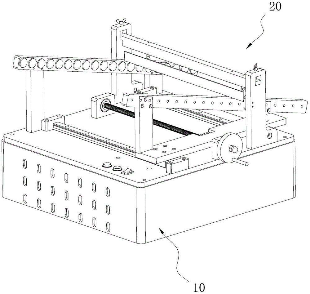
As shown in fig. 1-2, a testing fixture for inspecting a PCB pin is provided, which includes a bottom supporting mechanism 10 and a testing mechanism 20, wherein the bottom supporting mechanism 10 is provided with an inner cavity, and a control system is arranged in the inner cavity; the testing mechanism 20 comprises a bottom plate 21, a portal frame 22, a guiding assembly 23 and an induction assembly 24, wherein the bottom plate 21 is arranged on the bottom supporting mechanism 10, the portal frame 22 is arranged on the bottom plate 21, the guiding assembly 23 is arranged on the bottom plate 21 and penetrates through the lower portion of a cross beam of the portal frame 22, the induction assembly 24 is arranged on the portal frame 22, and a gap structure for a PCB to pass through is arranged between the output end of the induction assembly 24 and the output end of the guiding assembly 23; the sensing assembly 24 includes a distance sensing unit 241, a deflection detecting plate 242 and a rotating connector 243, the rotating connector 243 is disposed on a beam of the gantry 22, one end of the deflection detecting plate 242 is connected to an output end of the rotating connector 243, the distance sensing unit 241 is disposed on a side wall of the gantry 22, an output end of the sensing unit is aligned with a free end of the deflection detecting plate 242, and the sensing unit is electrically connected to the control system and is configured to feed back a distance parameter between the free end of the deflection detecting plate 242 and the output end of the distance sensing unit 241 to the control system.
Specifically, this a test fixture for checking PCB pin's theory of operation: the PCB to be detected is prevented from being arranged at the output end of the guide assembly 23, the PCB is driven to move along the output direction of the guide assembly 23 to enable the PCB to pass below the deflection detection plate 242, if the pin of the PCB is too long, the pin of the PCB abuts against the lower end of the deflection detection plate 242 and enables the deflection detection plate 242 to rotate and swing, the distance sensing unit 241 detects the change of the distance between the lower end of the deflection detection plate 242 and the output end of the deflection detection plate 242 and feeds a change signal back to the control system, and the control system gives an alarm to prompt that the pin of the PCB is bad; compare PCB circuit board in prior art and place its pin length of measuring with the slide rule after on the tool body, detection efficiency is low and need consume a large amount of manual operations, and the practicality is low, is unfavorable for the technical problem of enterprise development, the embodiment of the utility model provides a test fixture for detecting PCB pin adopts apart from sensing unit 241 and beat detection board 242, and through the output distance change data collection of beat detection board 242 and apart from sensing unit 241, realize the PCB circuit board of the bad pin of quick letter sorting, greatly improved PCB circuit board pin detection efficiency, be favorable to enterprise development.
In this embodiment, the rotating connector 243 includes a connecting seat, a connecting hinge and a return spring, the connecting seat is disposed at the bottom of the beam of the gantry 22, one end of the connecting hinge is fixedly connected to the connecting seat, the other end of the connecting hinge is fixedly connected to the upper end of the deflection detecting plate 242, and the return spring is disposed between the connecting hinge and the connecting seat and is used for returning the connecting hinge; the connecting seat is located above the output end of the distance sensing unit 241, the distance sensing unit 241 is a photoelectric distance sensor, the bottom of the deflection detecting plate 242 extends downward and passes through the output end sensing path of the distance sensing unit 241, and specifically, when the deflection detecting plate 242 is in a static state, the deflection detecting plate 242 is perpendicular to the bottom plate 21.
In this embodiment, the deflection detection plate 242 is a rectangular plate-shaped structure, and the multiple groups of the rotating connectors 243 are distributed at intervals along the length direction of the beam of the gantry 22, the upper end of the deflection detection plate 242 is connected with the output ends of all the rotating connectors 243, so that the multiple groups of the rotating connectors 243 are favorable for improving the connection effect, and the structural stability of the deflection detection plate 242 is ensured.
In this embodiment, the portal frame 22 includes the tie-beam 221, the adjusting part 222 and the column 223, the number of the column 223 is two sets of, and two sets of the column 223 symmetry sets up the upper end both sides of the bottom plate 21, the number of the adjusting part 222 is two sets of, and two sets of the adjusting part 222 one-to-one sets up respectively at two sets of the upper end of the column 223, the both ends of the tie-beam 221 one-to-one respectively with two sets of the output fixed connection of adjusting part 222, the swivel joint member 243 sets up the bottom of the tie-beam 221, adopt the adjusting part 222 to be favorable to improving the height of this tie-beam 221, make the lower extreme position of beat detection board 242 change along with it for the pin detection that the different length requirements of adaptation is favorable to improving the practicality of this test fixture.
In this embodiment, the upper end of the upright column 223 is provided with an opening sliding groove, the opening sliding groove penetrates through two opposite side surfaces of the upright column 223, the adjusting component 222 comprises a knob 224 and a rotating shaft 225, the rotating shaft 225 is rotatably connected to the top end of the upright column 223, the lower end of the rotating shaft 225 extends into the opening sliding groove, the upper end of the rotating shaft 225 extends to the upper side of the upright column 223, the knob 224 is arranged at the upper end of the rotating shaft 225, the lower end of the rotating shaft 225 is provided with a first thread, the end part of the connecting beam 221 is provided with a connecting hole, a second thread for being in threaded connection with the first thread is arranged in the connecting hole, and the position adjustment of the deflection detecting plate 242 can be realized through manual adjustment of an operator by adopting a structure similar to screw rod transmission.
In this embodiment, the guiding assembly 23 includes a first supporting rail 231 and a second supporting rail 232, the first supporting rail 231 and the second supporting rail 232 are symmetrically disposed on the bottom plate 21, the first supporting rail 231 and the second supporting rail 232 are both located under the beam of the portal frame 22, the first supporting rail 231 and the upper end surface of the second supporting rail 232 are coplanar, the gap structure is formed between the upper end surface of the first supporting rail 231 and the upper end surface of the second supporting rail 232 and the lower end of the deflection detecting plate 242, and the guiding structure for guiding the PCB circuit board to move is formed by adopting two sets of supporting rail structures, so as to be beneficial to adapting to PCB circuit boards with different shapes, and improve the practicability of the testing jig.
In this embodiment, the bottom plate 21 is provided with a linear assembly 211, the first support rail 231 is disposed at an output end of the linear assembly 211, an output direction of the output end of the linear assembly 211 is perpendicular to a length direction of the second support rail 232, and specifically, the linear assembly 211 can drive the first support rail 231 to move parallel to the second support rail 232, so as to adjust a distance between the first support rail 231 and the second support rail 232, so as to adapt to PCB circuit boards with different widths.
Example two
In this embodiment, the first supporting rail 231 and the second supporting rail 232 are rotatably connected to the opposite sidewalls of the first supporting rail 231 and the second supporting rail 232, respectively, and a first roller 234 and a second roller are rotatably connected to the opposite sidewalls of the first supporting rail 231 and the second supporting rail 232, and the upper end bearing surfaces of the first roller 234 and the first roller 234 are formed into a guide groove for guiding the PCB to slowly pass through the output end of the sensing assembly 24.
Specifically, the PCB is placed on the first roller 234 and the second roller, and when the PCB passes through the output end of the sensing assembly 24, because the first roller 234 and the second roller are respectively connected with the first support rail 231 and the second support rail 232 in a damping rotation manner, the PCB passes through the sensing assembly 24 at a slow moving speed, and the pins of the PCB cannot generate a wind breaking effect; compare in the test fixture who adopts smooth track as PCB circuit board guide structure among the prior art, when the test, smooth track can lead to the removal velocity of PCB circuit board too fast, and produced vibration effect is used in adjustable fender when the pin is broken wind, and PCB circuit board that probably leads to the pin to be normal is judged as the defective products by the mistake, seriously influences the technical problem who detects precision, the utility model provides a test fixture adopts the speed of damping connection PCB circuit board pin when response subassembly 24 through the gyro wheel of damping connection on direction subassembly 23 effectively, has avoided the condition of false retrieval to take place, and the detection precision of this test fixture of effectual improvement is favorable to enterprise's development.
In this embodiment, the circumferential side walls of the first roller 234 and the second roller are respectively provided with a silica gel layer for increasing the friction force between the first roller 234 and the end surfaces of the second roller and the PCB, and the silica gel layer structure is adopted to facilitate further controlling the moving speed of the PCB.
In this embodiment, two sets of bracket assemblies are disposed on the bottom plate 21 for mounting the first support rail 231 and the second support rail 232, respectively, each bracket assembly includes a first connecting column 235 and a second connecting column 236, the first connecting column 235 and the second connecting column 236 are vertically disposed on the bottom plate 21 and are disposed at two sides of the portal frame 22, respectively, the first connecting column 235 is lower than the second connecting column 236, the first support rail 231 and the second support rail 232 are connected to the upper ends of the first connecting column 235 and the second connecting column 236 and are disposed in an inclined state, because the heights of the first connecting column 235 and the second connecting column 236 are different, the first support rail 231 and the second support rail 232 are disposed in an inclined state, when a PCB circuit board is prevented from being at the high positions of the first support rail 231 and the second support rail 232, the PCB circuit board automatically and slowly moves along the inclined directions of the first support rail 231 and the second support rail 232 under the action of gravity, realize the automatic movement effect, be favorable to improving this test fixture's practicality.
In this embodiment, the upper ends of the first connecting column 235 and the second connecting column 236 are respectively provided with a plurality of threaded holes, and the first connecting column 235 and the second connecting column 236 are both fixedly connected with the first supporting rail 231 or the second supporting rail 232 through screws; wherein, first spliced pole 235 with the width of second spliced pole 236 is greater than first support rail 231 with the width of second support rail 232, first spliced pole 235 with the upper end shaping of second spliced pole 236 has and is used for holding first support rail 231 or the recess of second support rail 232, the cross-section of recess is the rhombus setting, adopts first support rail 231 of groove structure installation and second support rail 232 to be favorable to improving this guide assembly 23's structural stability, prevents that PCB circuit board from removing the in-process and producing vibrations and influence the test result.
In this embodiment, linear component 211 includes mounting panel 212, the vice 213 of first guide rail and driving source 214, the vice 213 of first guide rail sets up on the bottom plate 21, the length direction of the vice 213 of first guide rail with the length direction of second support rail 232 is perpendicular, mounting panel 212 is fixed to be set up on the slider of the vice 213 of first guide rail, the output of driving source 214 with the end fixing of mounting panel 212 is connected for the installation the bracket component setting of first support rail 231 is in on the mounting panel 212, adopt driving source 214 drive mounting panel 212 to remove, realize the distance of first support rail 231 and second support rail 232 and adjust, and then the PCB circuit board of the different width of adaptation, this simple structure, the installation of being convenient for is favorable to improving this test fixture's practicality.
In this embodiment, the number of the first guide rail pairs 213 is two, two sets of the first guide rail pairs 213 are located at two sides of the gantry 22, two ends of the mounting plate 212 are respectively fixedly connected with the sliding blocks of the two sets of the first guide rail pairs 213, and the two sets of the guide rails are adopted to facilitate improvement of the structural stability of the mounting plate 212.
In this embodiment, the driving source 214 includes a driving handle 215 and a screw pair 216, the driving handle 215 is disposed on the bottom plate 21, a screw of the screw pair 216 is rotatably connected to the bottom plate 21 and disposed along a length direction of the first guide rail pair 213, a nut of the screw pair 216 is fixedly disposed on the mounting plate 212, an output end of the driving handle 215 is drivingly connected to the screw of the screw pair 216, the driving handle 215 is convenient for manual operation, and compared with the expensive motor driving source 214, the driving source is beneficial to reducing the manufacturing cost of the test fixture and is beneficial to enterprise development.
The rest of this embodiment is the same as the first embodiment, and the unexplained features in this embodiment are explained by the first embodiment, which is not described herein again.
EXAMPLE III
The bottom support mechanism 10 comprises a first shell 11 and a second shell 12, the first shell 11 and the second shell 12 are respectively provided with a first opening cavity and a second opening cavity, the first shell 11 is arranged in the second opening cavity, and a control system is arranged in the first opening cavity; the PCB test fixture further comprises a heat dissipation mechanism 30, wherein the heat dissipation mechanism 30 comprises a fan assembly 31 and a mounting ring 32, the mounting ring 32 is arranged on the inner wall of the second opening cavity, a gap is formed between the mounting ring 32 and the bottom wall of the second opening cavity, the first shell 11 is arranged on the mounting ring 32, and the fan assembly 31 is arranged at the bottom of the first shell 11 and is electrically connected with the control system; the bottom plate 21 is disposed at the open ends of the first housing 11 and the second housing 12; the first casing 11 and the second casing 12 are respectively provided with a first heat dissipation hole 33 and a second heat dissipation hole 34 on the side wall thereof, the bottom wall of the first casing 11 is provided with a third heat dissipation hole 35 aligned with the fan assembly 31, a fourth heat dissipation hole 36 is arranged below the side wall of the second casing 12, the fourth heat dissipation hole 36 and the second heat dissipation hole 34 are respectively located at the upper side and the lower side of the mounting ring 32, and the output end and the input end of the fan assembly 31 are respectively aligned with the bottom wall of the second casing 12 and the third heat dissipation hole 35.
Specifically, the working principle of the test fixture is as follows: the fan assembly 31 blows air to the bottom wall of the second housing 12, external air enters the first open cavity through the first heat dissipation hole 33 and the second heat dissipation hole 34, exchanges heat with a heating element in the first open cavity, enters the second open cavity through the third heat dissipation hole 35 driven by the fan assembly 31, and is discharged out of the test fixture through the fourth heat dissipation hole 36 to realize heat dissipation; compare the test fixture among the prior art and set up the louvre that the inner chamber of intercommunication installed the unit that generates heat through the lateral wall and dispel the heat, the radiating effect is poor, and the durable degree that leads to PCB test fixture is low, and the practicality is poor, is unfavorable for the technical problem of enterprise development, the embodiment of the utility model provides a test fixture adopts fan assembly 31 and the cooperation of four group's louvres, forms directional gas flow channel in installing the electron device that generates heat, makes the outside air can take away the heat of the electron device that generates heat effectively, effectively reduces electron device's temperature, and then improves this test fixture's durable degree, is favorable to improving this test fixture's practicality, is favorable to enterprise development.
In this embodiment, the collar 32 is kept away from the one end of the inner wall of second opening die cavity is provided with the annular mounting groove, 11 joints of first casing are in on the annular mounting groove, collar 32 is formed by copper alloy or aluminum alloy material preparation, adopts annular mounting groove structure to be favorable to realizing this first casing 11's location effect, prevents first casing 11 off normal, improves this test fixture's installation convenience.
In this embodiment, a plurality of heat dissipation ribs 37 are disposed on the outer side wall of the first housing 11, the heat dissipation ribs 37 are distributed between the first heat dissipation holes 33, the upper ends of the heat dissipation ribs 37 are connected to the bottom of the testing mechanism 20, the lower ends of the heat dissipation ribs 37 are connected to the mounting ring 32, a heat dissipation flow channel is formed between two adjacent heat dissipation ribs 37 to communicate the first heat dissipation holes 33 and the second heat dissipation holes 34, each heat dissipation rib 37 is made of copper alloy or aluminum alloy, and the metal heat dissipation rib 37 structure is favorable for increasing the contact area between the air and the first housing 11, so as to improve the heat dissipation effect.
In this embodiment, the heat dissipation ribs 37 are arranged in a fin-shaped structure, the heat dissipation ribs 37 are obliquely arranged between the first casing 11 and the second casing 12, and the obliquely arranged fins can further increase the contact area between the heat dissipation ribs 37 and the gas, thereby improving the heat dissipation effect.
In this embodiment, the first heat dissipation hole 33, the second heat dissipation hole 34 and the fourth heat dissipation hole 36 are all disposed in a waist-hole-shaped structure.
In this embodiment, the number of the third heat dissipation holes 35 is multiple groups, wire holes 38 for supplying the fan assembly 31 and the control system to be electrically connected are formed in the bottom wall of the first opening cavity, and the multiple groups of the third heat dissipation holes 35 are uniformly distributed around the wire holes 38.
In this embodiment, the cross section of the third heat dissipation hole 35 is disposed in an elliptical shape.
In this embodiment, the fan assembly 31 includes a heat dissipation fan and a power supply unit, the power supply unit is connected between the control system and the heat dissipation fan, the heat dissipation fan is disposed at the bottom of the first housing 11, an input end of the heat dissipation fan faces the third heat dissipation hole 35, and an output end of the heat dissipation fan is aligned with the bottom wall of the second housing 12.
The rest of this embodiment is the same as the first embodiment, and the unexplained features in this embodiment are explained by the first embodiment, which is not described herein again.
Example four
The PCB testing jig further comprises an insulating mounting mechanism 40, wherein the insulating mounting mechanism 40 comprises a positioning rib 41 and a limiting seat 42, the positioning rib 41 is arranged on the outer side wall of the first shell 11, the limiting seat 42 is arranged on the inner side wall of the second shell 12, a limiting groove for clamping and matching the positioning rib 41 is arranged on the limiting seat 42, and a boss 44 abutted against the bottom of the positioning rib 41 is arranged on the bottom wall of the limiting groove; the limiting seat 42 is made of an insulating rubber material.
Specifically, the first housing 11 and the second housing 12 are connected through the positioning rib 41 and the limiting seat 42, so that a gap structure exists between the first housing 11 and the second housing 12, and the electron transmission between the first housing 11 and the second housing 12 is isolated, and the limiting seat 42 is made of an insulating rubber material, so that electrons are prevented from being transmitted between the first housing 11 and the second housing 12 through the positioning rib 41 and the limiting seat 42; compare test fixture in prior art and adopt metal material as the shell, lead to the shell to have stronger electrically conductive function, produce the shell electrified and form electric leakage phenomenon easily, when influencing the test result, have serious potential safety hazard, be unfavorable for the technical problem of enterprise development, the embodiment of the utility model provides a test fixture adopts the effectual transmission of stopping the electron between the metal casing of second grade insulation structure, prevents effectively that electric leakage phenomenon from appearing, simultaneously, can guarantee this metal casing's radiating effect again, improves this test fixture practicality, is favorable to the enterprise development.
In this embodiment, the cross section of the limiting seat 42 is formed in an Contraband-shaped structure, the limiting groove is formed in the middle of the limiting seat 42, and the opening faces the first housing 11, Contraband-shaped structure is beneficial to improving the contact surface between the limiting groove and the positioning rib 41, and improving the positioning effect.
In this embodiment, be provided with in the spacing seat 42 and be used for reducing the buffer cavity 43 of the mechanical vibration range of first casing 11 adopts buffer cavity 43 to be favorable to turning into elastic connection with the rigid connection between locating rib 41 and the spacing seat 42, and when second casing 12 received the vibration influence, this buffer cavity 43 was effectual to be used for the impact force elimination on locating rib 41 with second casing 12, guarantees the stability of first casing 11, prevents the influence of external vibration to the electron device in first casing 11, improves this test fixture's practicality.
In this embodiment, the positioning rib 41 is arranged in a sleeve-shaped structure, a buffer cavity 43 for reducing the mechanical vibration amplitude of the first housing 11 is arranged in the positioning rib 41, and the positioning rib 41 is made of a hard plastic material.
In this embodiment, a plurality of sets of support pillars for supporting the first housing 11 are disposed at the bottom of the second housing 12, and the support pillars are made of plastic.
In this embodiment, the first casing 11 with second casing 12 is provided with the multiunit sound absorbing hole for each other on the relative lateral wall, adopts sound absorbing structure to be favorable to reducing first casing 11 and second casing 12 and receives external noise interference, guarantees the test effect.
The rest of the present embodiment is the same as the embodiment, and the unexplained features in the present embodiment are all explained by the third embodiment, and are not repeated herein, wherein the positioning rib 41 in the present embodiment replaces the heat dissipation rib 37 described in the third embodiment, the boss 44 replaces the mounting ring 32 to support the first housing 11, the positioning rib 41 is made of a metal material and has a fin-shaped structure, and the first heat dissipation hole 33 and the second heat dissipation hole 34 are distributed on two sides of the positioning rib 41 and the limiting seat 42, so that the test fixture has both heat dissipation and leakage prevention functions.
The above description is only exemplary of the present invention and should not be taken as limiting the scope of the present invention, as any modifications, equivalents, improvements and the like made within the spirit and principles of the present invention are intended to be included within the scope of the present invention.