Condenser for boiler tail gas
Technical Field
The utility model belongs to the technical field of boiler tail gas treatment, a boiler tail gas's condenser is related to.
Background
The smoke temperature of most of domestic gas (oil) hot water boilers is above 160 ℃, and the steam boiler is as high as 220 ℃. The method aims to avoid that when the fuel contains sulfur and acidic substances such as NOx compounds and the like generated in the combustion process, the acidic substances generate acid condensation at the tail part of a heating surface to corrode the tail heating surface when the temperature is lower than 150 ℃, so that the strength of the tail heating surface is reduced, the safe operation of a boiler is damaged, and the boiler is scrapped in advance. Therefore, the design exhaust gas temperature of domestic and foreign conventional oil and gas boilers is generally more than 160 ℃, and the thermal efficiency is generally 86-90%. A great deal of sensible heat and latent heat of the exhaust gas are wasted.
The fuel heating value used in the current thermodynamic calculation standard in China refers to the lower heating value of the fuel, and the lower heating value does not count latent heat. However, when we use natural gas as fuel, since it contains a large amount of hydrogen, its latent heat and sensible heat are considerable, so that the boiler condenser can recover a large amount of heat energy in the exhaust gas, significantly improving the boiler thermal efficiency, making it close to or over 100%. Bringing considerable economic benefit for users. The boiler condenser is additionally arranged at the tail part of the boiler, the exhaust gas temperature of the boiler is reduced by utilizing the heat exchange principle, the temperature of the feed water of the boiler is increased, and the purposes of saving fuel, saving energy and protecting environment are achieved. Generally, the flue gas-liquid boiler condenser and the flue gas-air boiler condenser are mainly divided into a flue gas-liquid boiler condenser and a flue gas-air boiler condenser according to purposes and exchange media, and a full stainless steel 304 frame and a stainless steel spiral finned tube are adopted, so that the flue gas-air boiler condenser has the characteristics of high heat transfer speed, energy conservation, attractiveness, durability and the like. However, such fins are slow to dissipate heat, resulting in poor condensation.
SUMMERY OF THE UTILITY MODEL
The utility model aims at having above-mentioned problem to current technique, provided a boiler tail gas's condenser for natural gas boiler tail gas waste heat recovery and condensate recovery use as condensing boiler afterbody heated surface, also can regard as air cooler heat transfer part, and the three-dimensional whole one shot forming of heat exchanger fin strengthens heat transfer in the gas side, and the heat exchanger fin property more is favorable to the emission of condensate, energy-efficient.
The purpose of the utility model can be realized by the following technical proposal: the utility model provides a condenser of boiler tail gas, including being square braced frame, be wavy heat exchanger fin, the condenser tube subassembly, inlet manifold and outlet manifold, a serial communication port, braced frame includes two front and back end plates, go up roof and lower plate, the condenser tube subassembly includes a plurality of straight tubes that set up side by side and connects the U type that the straight tube is established ties together, it has confession straight tube male round hole to open on the heat exchanger fin, a plurality of heat exchanger fin is overlapped together and vertical placing in braced frame, it has the bar hole that the cooling water pipe subassembly wore out to supply to open on the end plate, a plurality of condenser tube subassembly sets gradually along braced frame's direction of height, the end of intaking and the inlet manifold intercommunication of condenser tube subassembly, the play water end and the outlet manifold intercommunication of condenser tube subassembly, be connected with the discharge pipe comdenstion water on the lower plate.
One side of a supporting frame in high-temperature tail gas of the boiler enters, the other side of the supporting frame goes out, the tail gas passes through the heat exchange fins which are vertically arranged, the heat exchange fins absorb heat of the tail gas, the tail gas is cooled and condensed to form liquid drops, the liquid drops are collected to the lower bottom plate along the wavy heat exchange fins, and the condensed water is discharged through a condensed water discharge pipe. The heat exchanger fin need dispel the heat after the heat absorption, in order to accelerate the heat dissipation of heat exchanger fin, injects cold water in the condenser tube subassembly, and the straight tube is in the inside cold water of heat conduction of heat exchanger fin, and cold water circulation constantly gets into from inlet manifold, and through the straight tube, goes out from outlet manifold again for heat exchanger fin rapid cooling improves the condensation effect of this condenser.
Furthermore, the strip-shaped holes are obliquely arranged, and the inclination angle is 30-45 degrees.
Furthermore, braced frame one side is the tail gas import, and the opposite side is the tail gas export, the vertical setting of inlet manifold just is close to the tail gas export, the vertical setting of outlet manifold just is close to the tail gas import.
Furthermore, the heat exchange plate is formed by three-dimensional integrated molding of a stainless steel plate, and wave crests and wave troughs on the heat exchange plate are formed by pressing the whole plate in a concave-convex mode.
Furthermore, the round holes on the heat exchange plates are longitudinally distributed at equal intervals, and the adjacent longitudinal rows are arranged in a staggered manner.
Compared with the prior art, the condenser for the boiler tail gas has the following advantages:
1. the heat exchange material uses corrosion-resistant stainless steel with high finned ratio, and the steel consumption is reduced by more than 50% compared with a common spiral finned tube heat exchanger;
2. the specially designed sine wave heat exchange plate is integrally formed in three dimensions, heat transfer is enhanced on the gas side, the properties of the heat exchange plate are more beneficial to the discharge of condensate, and the heat exchange plate is efficient and energy-saving.
Drawings
FIG. 1 is a front view of the condenser for boiler tail gas.
FIG. 2 is a side view of the condenser for boiler tail gas.
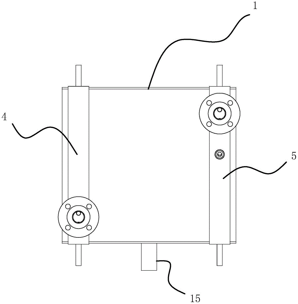
FIG. 3 is a top view of the condenser for the boiler tail gas.
Fig. 4 is an assembly view of the support frame and the cooling water pipe assembly.
Fig. 5 is a schematic structural view of the support frame.
Fig. 6 is a schematic structural view of the cooling water pipe assembly.
Figure 7 is a front view of the plate.
FIG. 8 is a partial cross-sectional view of a plate.
In the figure, 1, a support frame; 11. an end plate; 12. an upper top plate; 13. a lower base plate; 14. a strip-shaped hole; 15. a condensed water discharge pipe; 2. a heat exchanger fin; 21. a circular hole; 3. a cooling water tube assembly; 31. a straight pipe; 32. a U-shaped joint; 4. a water inlet main pipe; 5. and (4) a water outlet main pipe.
Detailed Description
The following are specific embodiments of the present invention and the accompanying drawings are used to further describe the technical solution of the present invention, but the present invention is not limited to these embodiments.
As shown in figures 1, 2, 3 and 4, the condenser for boiler tail gas comprises a square support frame 1, wave-shaped heat exchange plates 2, a cooling water pipe assembly 3, a water inlet main pipe 4 and a water outlet main pipe 5, wherein the support frame 1 comprises a front end plate 11, a rear end plate 11, an upper top plate 12 and a lower bottom plate 13, the cooling water pipe assembly 3 comprises a plurality of straight pipes 31 arranged side by side and U-shaped joints 32 connecting the straight pipes 31 in series, round holes 21 for inserting the straight pipes 31 are formed in the heat exchange plates 2, the heat exchange plates 2 are overlapped and vertically placed in the support frame 1, strip-shaped holes 14 for allowing the cooling water pipe assembly 3 to penetrate are formed in the end plates 11, the cooling water pipe assemblies 3 are sequentially arranged along the height direction of the support frame 1, the water inlet ends of the cooling water pipe assemblies 3 are communicated with the water inlet main pipe 4, the water outlet ends of the cooling water pipe assemblies 3 are communicated with the water outlet main pipe 5, the lower plate 13 is connected to a condensate discharge pipe 15.
As shown in fig. 5 and 6, the strip-shaped holes 14 are obliquely arranged, the inclination angle is 30-45 °, one side of the support frame 1 is a tail gas inlet, the other side of the support frame is a tail gas outlet, the water inlet header pipe 4 is vertically arranged and close to the tail gas outlet, and the water outlet header pipe 5 is vertically arranged and close to the tail gas inlet.
As shown in fig. 7 and 8, the heat exchanger plate 2 is formed by three-dimensionally and integrally forming a stainless steel plate, the wave crests and the wave troughs on the heat exchanger plate 2 are formed by pressing the whole plate, the circular holes 21 on the heat exchanger plate 2 are distributed at equal intervals in the longitudinal direction, and the adjacent longitudinal lines are arranged in a staggered manner.
One side of a supporting frame 1 in high-temperature tail gas of the boiler enters, the other side of the supporting frame is discharged, the tail gas passes through a heat exchange plate 2 which is vertically arranged, the heat exchange plate 2 absorbs heat of the tail gas, the tail gas is cooled and condensed into liquid drops, the liquid drops are collected onto a lower bottom plate 13 along the wavy heat exchange plate 2, and the liquid drops are discharged by a condensed water discharge pipe 15. The heat exchanger fin 2 need dispel the heat after absorbing heat, in order to accelerate the heat dissipation of heat exchanger fin 2, injects cold water in condenser tube subassembly 3, and straight tube 31 conducts the heat of heat exchanger fin 2 to inside cold water, and cold water circulation constantly gets into from inlet manifold 4, through straight tube 31, goes out from outlet manifold 5 again for 2 rapid cooling of heat exchanger fin improve the condensation effect of this condenser.
The specific embodiments described herein are merely illustrative of the spirit of the invention. Various modifications, additions and substitutions for the specific embodiments described herein may be made by those skilled in the art without departing from the spirit of the invention or exceeding the scope of the invention as defined in the accompanying claims.