CN214194711U - Dredging device for hydraulic engineering - Google Patents
Dredging device for hydraulic engineering Download PDFInfo
- Publication number
- CN214194711U CN214194711U CN202022345380.6U CN202022345380U CN214194711U CN 214194711 U CN214194711 U CN 214194711U CN 202022345380 U CN202022345380 U CN 202022345380U CN 214194711 U CN214194711 U CN 214194711U
- Authority
- CN
- China
- Prior art keywords
- loading board
- pivot
- wall
- bearing frame
- driving motor
- Prior art date
- Legal status (The legal status is an assumption and is not a legal conclusion. Google has not performed a legal analysis and makes no representation as to the accuracy of the status listed.)
- Active
Links
- 239000000463 material Substances 0.000 claims description 21
- 238000003466 welding Methods 0.000 claims description 10
- 238000003860 storage Methods 0.000 claims description 7
- 238000007599 discharging Methods 0.000 claims description 6
- XLYOFNOQVPJJNP-UHFFFAOYSA-N water Substances O XLYOFNOQVPJJNP-UHFFFAOYSA-N 0.000 claims description 6
- 239000013049 sediment Substances 0.000 claims description 5
- 239000002184 metal Substances 0.000 claims description 4
- 230000008878 coupling Effects 0.000 claims description 3
- 238000010168 coupling process Methods 0.000 claims description 3
- 238000005859 coupling reaction Methods 0.000 claims description 3
- 230000008901 benefit Effects 0.000 abstract description 2
- 238000000034 method Methods 0.000 abstract description 2
- 238000007790 scraping Methods 0.000 description 8
- 230000000694 effects Effects 0.000 description 2
- 238000003780 insertion Methods 0.000 description 2
- 230000037431 insertion Effects 0.000 description 2
- 208000034189 Sclerosis Diseases 0.000 description 1
- 230000008859 change Effects 0.000 description 1
- 238000004140 cleaning Methods 0.000 description 1
- 230000007547 defect Effects 0.000 description 1
- 238000009826 distribution Methods 0.000 description 1
- 239000003292 glue Substances 0.000 description 1
- 238000012986 modification Methods 0.000 description 1
- 230000004048 modification Effects 0.000 description 1
- 230000008569 process Effects 0.000 description 1
- 230000001737 promoting effect Effects 0.000 description 1
- 239000010802 sludge Substances 0.000 description 1
- 239000002689 soil Substances 0.000 description 1
- 238000003756 stirring Methods 0.000 description 1
Images


Landscapes
- Barrages (AREA)
Abstract
The utility model belongs to the technical field of the desilting technique and specifically relates to a desilting device for hydraulic engineering, including the loading board, the bottom of loading board is provided with two pairs of primary shaft bearing, and is two pairs all interlude and be equipped with the pivot between the primary shaft bearing, the gyro wheel is all installed to the tip of pivot, the up end fixed mounting of loading board has driving motor, driving motor passes through drive chain and is connected with the pivot, the up end middle part of loading board runs through and is provided with feeding device, the bottom of loading board is provided with scrapes the wall device, and this desilting device for hydraulic engineering compares current desilting device clearance more thoroughly, has the efficient advantage of clearance.
Description
Technical Field
The utility model relates to a sediment removal device especially relates to a sediment removal device for hydraulic engineering.
Background
At present, in order to facilitate drainage in rural areas, a U-shaped channel is dug at one side of a paddy field, and a concrete U-shaped groove is arranged in the channel, but the existing concrete U-shaped groove silts up for years, silt and garbage cannot be cleaned in time, so that the concrete U-shaped groove is blocked, the drainage and circulation of water are seriously influenced, and serious consequences and loss can be generated once flood situations occur.
Chinese publication No. CN206680955U discloses a dredging device for hydraulic engineering, which can dredge according to the shape of a U-shaped groove. However, the dredging device cannot remove the sludge at the bottom of the ditch according to the adjustment of the dredging depth, and the working efficiency and the application range are affected.
SUMMERY OF THE UTILITY MODEL
The utility model aims at solving the defects existing in the prior art and providing a dredging device for hydraulic engineering.
In order to achieve the above purpose, the utility model adopts the following technical scheme:
the design is a dredging device for hydraulic engineering, including the loading board, the bottom of loading board is provided with two pairs of first bearing frames, and is two pairs all interlude between the first bearing frame and be equipped with the pivot, the gyro wheel is all installed to the tip of pivot, the up end fixed mounting of loading board has driving motor, driving motor passes through drive chain and is connected with the pivot, the up end middle part of loading board runs through and is provided with feeding device, the bottom of loading board is provided with scrapes the wall device.
Preferably, the feeding device includes the conveying pipeline, the conveying pipeline sets up the up end middle part at the loading board, the top of conveying pipeline is provided with the rotating electrical machines, the inner chamber of conveying pipeline is provided with the promotion spiral leaf, the power shaft of rotating electrical machines extends to in the conveying pipeline and is connected with the promotion spiral leaf through the shaft coupling, the bottom integrated into one piece of conveying pipeline is equipped with into the material shovel, the outer wall upside of conveying pipeline is connected with row material pipe, arrange the material pipe and be the slope form setting and with arrange the material pipe intercommunication.
Preferably, scrape the wall device and include the second bearing frame, the second bearing frame welding is in the bottom of loading board, the second bearing frame is passed in the pivot, the bottom welding of second bearing frame has the telescopic link, the telescopic link includes upper boom and lower beam, the vertical insertion in the upper boom in lower boom upper end, the bottom welding of lower beam has the rotation cross axle, the tip welding of rotation cross axle has scrapes the wall ware.
Preferably, the up end threaded connection of loading board has many rotatory bolts around arranging the material pipe distribution, the outer wall integrated into one piece of arranging the material pipe is equipped with the mounting panel, rotatory bolt passes the mounting panel and is connected with the bearing board fastening.
Preferably, a plurality of fixing holes are formed in the lower rod at intervals, a threaded hole is formed in the upper rod, a bolt is connected to the threaded hole in an internal thread mode, and the end portion of the bolt is screwed into the fixing holes and fastened.
Preferably, the upper end face of the bearing plate is welded with a pair of pushing handles in an L shape, the pushing handles are provided with control switches of a driving motor and a rotating motor, the bearing plate is provided with a storage battery, and the storage battery is electrically connected with the control switches, the driving motor and the rotating motor.
Preferably, the wall scraper is a pair of fan-shaped metal scrapers.
The utility model discloses technical effect includes:
the device has realized the function of basin desilting, hold in the in-service use process and push away can realize promoting the removal of loading board along the basin direction, when removing, the walking of whole device of driving motor drive, it realizes scraping the mud in the basin to drive the wall scraping ware during the walking, stir simultaneously, make the earth change glue thick not hard up, later drive rotating electrical machines is rotatory, rotating electrical machines drives and promotes the spiral leaf and rotates the mud of conveying pipeline bottom and discharge to basin one side to the row's material pipe at conveying pipeline top, convenient and fast, and can clear up after loosening the soil with the earth of sclerosis, it is more thorough to compare current desilting device clearance, the advantage that has the cleaning efficiency height.
Drawings
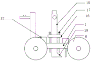
Fig. 1 is a schematic side view of the present invention;
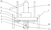
fig. 2 is a schematic front structural view of the present invention;
fig. 3 is a schematic structural view of the wall scraping device of the present invention;
fig. 4 is a schematic structural view of the feeding device of the present invention.
In the figure: the device comprises a bearing plate 1, a wall scraping device 2, a material conveying device 3, a first bearing seat 4, a rotating shaft 5, rollers 6, a wall scraping device 7, an expansion rod 8, a driving motor 9, a second bearing seat 10, a rotating transverse shaft 11, a storage battery 12, a material conveying pipe 13, a lifting spiral vane 14, a rotating motor 15, a mounting plate 16, a rotating bolt 17, a material discharging pipe 18, a material feeding shovel 19, an upper rod 20, a lower rod 21, a fixing hole 22, a threaded hole 23, a threaded bolt 24, a push handle 25 and a control switch 26.
Detailed Description
The technical solutions in the embodiments of the present invention will be described clearly and completely with reference to the accompanying drawings in the embodiments of the present invention, and it is obvious that the described embodiments are only some embodiments of the present invention, not all embodiments.
Referring to fig. 1-4, sediment removal device for hydraulic engineering, including loading board 1, scrape wall device 2, feeding device 3, the bottom of loading board 1 is provided with two pairs of first bearing frame 4, all alternate between two pairs of first bearing frame 4 and be equipped with pivot 5, gyro wheel 6 is installed at the both ends of pivot 5, loading board 1's up end fixed mounting has driving motor 9, driving motor 9 passes through drive chain and is connected with pivot 5, loading board 1's up end middle part is run through and is provided with feeding device 3, loading board 1's bottom is provided with scrapes wall device 2.
Conveying device 3 includes conveying pipeline 13, conveying pipeline 13 sets up the up end middle part at loading board 1, the top of conveying pipeline 13 is provided with rotating electrical machines 15, the inner chamber of conveying pipeline 13 is provided with promotes spiral leaf 14, rotating electrical machines 15's power shaft extends to in the conveying pipeline 13 and is connected with promotion spiral leaf 14 through the shaft coupling, the bottom integrated into one piece of conveying pipeline 13 is equipped with into material shovel 19, the outer wall upside of conveying pipeline 13 is connected with row material pipe 18, it is slope form setting and with row material pipe 18 intercommunication to arrange material pipe 18, rotating electrical machines 15 drives promotion spiral leaf 14 rotatory when circular telegram work, promote silt in the conveying pipeline 13 to arrange material pipe 18 and discharge, realize the function of desilting.
The upper end face of the bearing plate 1 is in threaded connection with a plurality of rotary bolts 17 distributed around the discharge pipe 18, the outer wall of the discharge pipe 18 is integrally formed with a mounting plate 16, and the rotary bolts 17 penetrate through the mounting plate 16 and are fixedly connected with the bearing plate 1. Be equipped with a plurality of mutual spaced fixed orificess 22 on the lower beam 21, be equipped with screw hole 23 on the upper beam 20, screw hole 23 female connection has bolt 24, the tip screw in fixed orificess 22 of bolt 24 and fastening, the upper beam 20 and the lower beam 21 of setting pass through bolt 24 fastening connection, when the degree of depth that wall ware 7 inserted the basin is scraped in needs regulation, can loosen bolt 24, can realize in inserting the fixed orificess 22 of different positions with bolt 24, make the device can adapt to the basin desilting work of the different degree of depth.
A pair of L-shaped push handles 25 are welded on the upper end face of the bearing plate 1, control switches 26 of the driving motor 9 and the rotating motor 15 are arranged on the push handles 25, a storage battery 12 is mounted on the bearing plate 1, and the storage battery 12 is electrically connected with the control switches 26, the driving motor 9 and the rotating motor 15.
The terminology used herein is for the purpose of description and illustration, rather than of limitation. As the present invention may be embodied in several forms without departing from the spirit or essential characteristics thereof, it should also be understood that the above-described embodiments are not limited by any of the details of the foregoing description, but rather should be construed broadly within its spirit and scope as defined in the appended claims, and therefore all changes and modifications that fall within the meets and bounds of the claims, or equivalences of such meets and bounds are therefore intended to be embraced by the appended claims.
Claims (7)
1. The utility model provides a sediment removal device for hydraulic engineering, includes loading board (1), its characterized in that, the bottom of loading board (1) is provided with two pairs of first bearing frame (4), and is two pairs all interlude between first bearing frame (4) and be equipped with pivot (5), gyro wheel (6) are all installed to the tip of pivot (5), the up end fixed mounting of loading board (1) has driving motor (9), driving motor (9) are connected with pivot (5) through drive chain, the up end middle part of loading board (1) runs through and is provided with feeding device (3), the bottom of loading board (1) is provided with scrapes wall device (2).
2. The dredging device for water conservancy project according to claim 1, wherein the conveying device (3) comprises a conveying pipe (13), the conveying pipe (13) is arranged in the middle of the upper end face of the bearing plate (1), a rotating motor (15) is arranged at the top of the conveying pipe (13), a lifting spiral vane (14) is arranged in an inner cavity of the conveying pipe (13), a power shaft of the rotating motor (15) extends into the conveying pipe (13) and is connected with the lifting spiral vane (14) through a shaft coupling, a material feeding shovel (19) is integrally formed at the bottom of the conveying pipe (13), a material discharging pipe (18) is connected to the upper side of the outer wall of the conveying pipe (13), and the material discharging pipe (18) is obliquely arranged and communicated with the material discharging pipe (18).
3. The sediment removal device for hydraulic engineering of claim 1, characterized in that, scrape wall device (2) and include second bearing frame (10), second bearing frame (10) welding is in the bottom of loading board (1), second bearing frame (10) is passed in pivot (5), telescopic link (8) are welded to the bottom of second bearing frame (10), telescopic link (8) include upper boom (20) and lower beam (21), lower beam (21) upper end is vertical to be inserted in upper boom (20), the bottom welding of lower beam (21) has rotation cross axle (11), the tip welding that rotates cross axle (11) has wall scraper (7).
4. The dredging device for water conservancy project according to claim 1 or 2, wherein the upper end surface of the bearing plate (1) is in threaded connection with a plurality of rotary bolts (17) distributed around the discharging pipe (18), the outer wall of the discharging pipe (18) is integrally formed with a mounting plate (16), and the rotary bolts (17) penetrate through the mounting plate (16) and are fixedly connected with the bearing plate (1).
5. The dredging device for the water conservancy project according to claim 3, wherein the lower rod (21) is provided with a plurality of fixing holes (22) which are spaced from each other, the upper rod (20) is provided with a threaded hole (23), a bolt (24) is connected with the threaded hole (23) in a threaded manner, and the end part of the bolt (24) is screwed into the fixing hole (22) and fastened.
6. The dredging device for the water conservancy project according to claim 1 or 2, wherein a pair of pushing handles (25) in an L shape are welded on the upper end face of the bearing plate (1), a control switch (26) of a driving motor (9) and a rotating motor (15) is arranged on each pushing handle (25), a storage battery (12) is mounted on the bearing plate (1), and the storage battery (12) is electrically connected with the control switch (26), the driving motor (9) and the rotating motor (15).
7. A dredging device for water conservancy projects according to claim 3, wherein the wall scraper (7) is a pair of fan-shaped metal scrapers.
Priority Applications (1)
| Application Number | Priority Date | Filing Date | Title |
|---|---|---|---|
| CN202022345380.6U CN214194711U (en) | 2020-10-19 | 2020-10-19 | Dredging device for hydraulic engineering |
Applications Claiming Priority (1)
| Application Number | Priority Date | Filing Date | Title |
|---|---|---|---|
| CN202022345380.6U CN214194711U (en) | 2020-10-19 | 2020-10-19 | Dredging device for hydraulic engineering |
Publications (1)
| Publication Number | Publication Date |
|---|---|
| CN214194711U true CN214194711U (en) | 2021-09-14 |
Family
ID=77642373
Family Applications (1)
| Application Number | Title | Priority Date | Filing Date |
|---|---|---|---|
| CN202022345380.6U Active CN214194711U (en) | 2020-10-19 | 2020-10-19 | Dredging device for hydraulic engineering |
Country Status (1)
| Country | Link |
|---|---|
| CN (1) | CN214194711U (en) |
-
2020
- 2020-10-19 CN CN202022345380.6U patent/CN214194711U/en active Active
Similar Documents
| Publication | Publication Date | Title |
|---|---|---|
| CN214784321U (en) | Efficient water conservancy construction sediment removal device | |
| CN219569028U (en) | Dredging device for irrigation ditch | |
| CN218880992U (en) | Excavator bucket with automatic cleaning function | |
| CN207846506U (en) | A kind of bull-dozer cleaning plant for building | |
| CN214832978U (en) | Adjustable bucket structure | |
| CN216075488U (en) | Municipal administration underground drainage pipe desilting device | |
| CN222252280U (en) | Channel dredging device for hydraulic engineering | |
| CN214272364U (en) | Efficient cleaning device for ground groove | |
| CN208167851U (en) | A kind of hydraulic engineering Accrete clearing device | |
| CN217439039U (en) | Novel canal and river dredging equipment | |
| CN111636503A (en) | Land ditching device with limiting and deviation rectifying structure for water conservancy pipeline laying tool | |
| CN216713158U (en) | High-efficiency integrated wall brushing device for grooving machine | |
| CN209653009U (en) | A mud scraper for river channel mud cleaning that is easy to adjust | |
| CN215387763U (en) | Sludge discharge device for sewage treatment | |
| CN216739577U (en) | Underground Diaphragm Wall Grooving Machine Composite Wall Brushing Device | |
| CN212317025U (en) | Silt clearance mechanism for hydraulic engineering | |
| CN210737666U (en) | Hydraulic engineering excavator bucket | |
| CN221255704U (en) | Scraper for chain type mud scraper | |
| CN207260227U (en) | A kind of static ribbon silt dredging mud machine | |
| CN119384897B (en) | Vegetation restoration device and method for coastal ecological management | |
| CN112546683A (en) | Sludge discharge port for efficiently removing bottom sludge | |
| CN111719610B (en) | A soil cleaning machine for Larsen steel sheet pile groove and its use method | |
| CN221878223U (en) | A land grader with soil loosening function | |
| CN221689178U (en) | Land leveling device | |
| CN213014426U (en) | Hydraulic engineering desilting device |
Legal Events
| Date | Code | Title | Description |
|---|---|---|---|
| GR01 | Patent grant | ||
| GR01 | Patent grant |