Bearing grinder oil mist processing apparatus
Technical Field
The utility model relates to an oil mist processing apparatus technical field specifically is a bearing grinding machine oil mist processing apparatus.
Background
A Grinding machine (Grinding machine) is a machine tool that uses a Grinding tool to grind a workpiece to obtain a desired shape, size, and precision machined surface. The machining action of the grinding machine, i.e. grinding, is the primary place in machining, the sharpening of cutting tools and the precise manufacture of machine parts are dependent on the grinding work, which is also part of the precision machining, the grinding machine being intended to carry out grinding with a high degree of precision and with a relatively small roughness, can carry out high-efficiency grinding, the grinding machine can process materials with rather high hardness, such as hardened steel, hard alloy and the like, and can also process materials with higher brittleness, such as glass, granite and the like, the oil mist treatment equipment is arranged on machine processing equipment which is easy to generate oil mist, water mist and dust particles, such as a machine tool, a cleaning machine and the like, the industrial environment-friendly equipment is used for collecting and purifying oil mist, water mist and dust particles, and the oil mist treatment equipment is professional equipment which is arranged on machine tools such as a CNC (computerized numerical control) machining center, a grinding machine and a lathe and solves the problem of oil mist, water mist and dust generated in machining.
Current bearing grinding machine oil mist processing apparatus, the oil mist is too much when the bearing factory carries out the grinding machine processing, lead to the workshop environment variation, the user can't avoid on one's body can be infected with the oil mist and cause the clothing to be difficult to wash, it is very bad smell always to have an oil mist taste on one's body, thereby the usability of bearing grinding machine oil mist processing apparatus has been influenced, and current bearing grinding machine oil mist processing apparatus is in the use in addition, the effect of handling to the oil mist is relatively poor, the work efficiency of bearing grinding machine oil mist processing apparatus has been reduced.
SUMMERY OF THE UTILITY MODEL
An object of the utility model is to provide a bearing grinding machine oil mist processing apparatus to it can not avoid being infected with the oil mist and cause the clothing to be difficult to wash to propose the user in solving above-mentioned background art, to the relatively poor problem of effect that the oil mist was handled.
In order to achieve the above object, the utility model provides a following technical scheme: a bearing grinding machine oil mist treatment device comprises a device main body, wherein a collecting tank is placed on one side inside the device main body, a first filter screen is arranged in the middle of the inside of the collecting tank, a support is fixed on the other side inside the device main body, a fan is installed at the top of the support, an air inlet end of the fan is connected with an air inlet pipe, an air outlet end of the fan is connected with an air outlet pipe extending to one side of the device main body, an oil mist separator is connected to one side of the air inlet pipe, a funnel is connected to the bottom of the oil mist separator, a second filter screen is arranged in the middle of the inside of the funnel, a slag outlet is formed in the middle of one side of the funnel, a placing frame is fixed on one side of the top of the device main body, a guide pipe is placed at the top of the placing frame, a telescopic pipe is connected to one side of the guide pipe, the telescopic pipe is connected with the oil mist separator, and a sliding groove is formed in the middle of the outer surface of the guide pipe, the inside of spout is provided with the slider, the top of slider is provided with the damping pivot, one side of damping pivot is connected with the inoxidizing coating through the connecting rod, the top of damping pivot is connected with and pushes away the piece, there is the chamber door surface one side of device main part through hinged joint.
Preferably, an operation panel is installed on one side of the device main body, and the operation panel is electrically connected with the fan and the oil mist separator respectively.
Preferably, the door is rotatably coupled to the apparatus main body by a hinge.
Preferably, the collecting tank is made of a transparent acrylic material, and the collecting tank is detachably arranged with the device main body.
Preferably, the second filter screen is inclined, and the second filter screen is matched with the slag outlet.
Preferably, the connecting rod is slidably connected with the guide tube through a sliding block and a sliding groove.
Preferably, the hopper is arranged perpendicular to the collection trough.
Compared with the prior art, the beneficial effects of the utility model are that: the bearing grinding machine oil mist treatment device is provided with a protective layer, a chute, a sliding block, a damping rotating shaft, a connecting rod and a pushing piece, wherein the outer surface of a guide pipe is respectively provided with the chute and the protective layer, the sliding block is arranged inside the chute, a user drives the sliding block and the chute to slide through the pushing piece in the use process, and the connecting rod rotates along with the damping rotating shaft when sliding, so that the protective layer is unfolded, the user is protected through the protective layer, the problem that oil mist is easily contaminated on the body and difficult to clean in the use process is avoided, the practicability of the bearing grinding machine oil mist treatment device is improved, meanwhile, the bearing grinding machine oil mist treatment device is also provided with a funnel, a first filter screen, a second filter screen, a slag hole and a collecting tank, the oil mist is treated through an oil mist separator, the treated oil mist flows into the collecting tank through the funnel, and the second filter screen is arranged in the middle of the inside of the funnel, the filter residue is separated from the oil through the second filter screen, and the filter residue falls to the first filter screen from the slag outlet for secondary filtration, so that the oil and the impurities are separated, and the treatment effect of the bearing grinding machine oil mist treatment device is improved.
Drawings
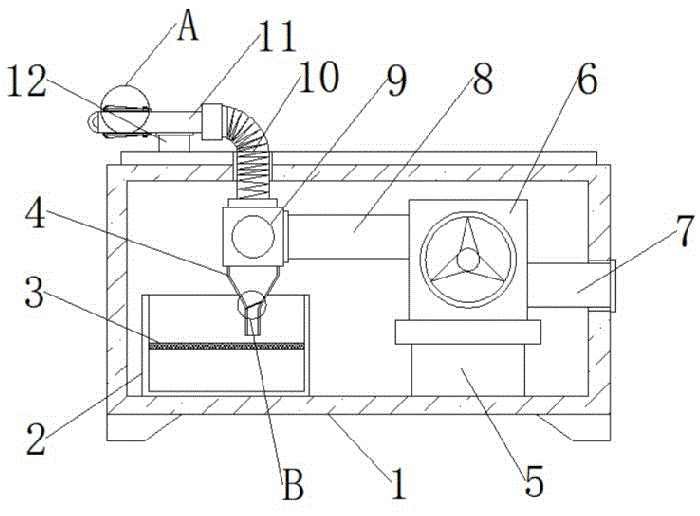
FIG. 1 is a schematic structural view of the present invention;
FIG. 2 is a schematic view of the internal structure of the device body of the present invention;
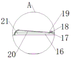
fig. 3 is a schematic view of a partially enlarged structure of the present invention a;
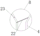
fig. 4 is a schematic diagram of a partially enlarged structure of the present invention B.
In the figure: 1. a device main body; 2. collecting tank; 3. a first filter screen; 4. a funnel; 5. a support; 6. A fan; 7. an air outlet pipe; 8. an air inlet pipe; 9. an oil mist separator; 10. a telescopic pipe; 11. a conduit; 12. Placing a rack; 13. a box door; 14. a hinge; 15. an operation panel; 16. a chute; 17. a slider; 18. A damping rotating shaft; 19. pushing the workpiece; 20. a connecting rod; 21. a protective layer; 22. a second filter screen; 23. a slag outlet.
Detailed Description
The technical solutions in the embodiments of the present invention will be described clearly and completely with reference to the accompanying drawings in the embodiments of the present invention, and it is obvious that the described embodiments are only some embodiments of the present invention, not all embodiments. Based on the embodiments in the present invention, all other embodiments obtained by a person skilled in the art without creative work belong to the protection scope of the present invention.
In the present invention, unless otherwise expressly stated or limited, the terms "disposed," "mounted," "connected," "fixed," "sleeved," and the like are to be construed broadly, e.g., as either a fixed connection, a removable connection, or an integral part; can be mechanically or electrically connected; the two elements may be connected directly or indirectly through an intermediate medium, and the two elements may be connected internally or in an interaction relationship, and a person skilled in the art can understand the specific meaning of the above terms in the present invention according to specific situations.
Referring to fig. 1-4, the present invention provides a technical solution: a bearing grinder oil mist treatment device comprises a device main body 1, a collecting tank 2, a first filter screen 3, a funnel 4, a support 5, a fan 6, an air outlet pipe 7, an air inlet pipe 8, an oil mist separator 9, a telescopic pipe 10, a guide pipe 11, a placing rack 12, a box door 13, a hinge 14, an operating panel 15, a sliding chute 16, a sliding block 17, a damping rotating shaft 18, a pushing piece 19, a connecting rod 20, a protective layer 21, a second filter screen 22 and a slag outlet 23, wherein the collecting tank 2 is placed on one side inside the device main body 1, the first filter screen 3 is arranged in the middle inside the collecting tank 2, the support 5 is fixed on the other side inside the device main body 1, the fan 6 is installed at the top of the support 5, the air inlet end of the fan 6 is connected with the air inlet pipe 8, the air outlet end of the fan 6 is connected with the air outlet pipe 7 extending to one side of the device main body, be provided with second filter screen 22 in the middle of the inside of funnel 4, slag notch 23 has been seted up in the middle of one side of funnel 4, top one side of device main part 1 is fixed with rack 12, pipe 11 has been placed at the top of rack 12, one side of pipe 11 is connected with flexible pipe 10, flexible pipe 10 is connected with oil mist separator 9, be provided with spout 16 in the middle of the surface of pipe 11, the inside of spout 16 is provided with slider 17, slider 17's top is provided with damping pivot 18, one side of damping pivot 18 is connected with the inoxidizing coating 21 through connecting rod 20, the top of damping pivot 18 is connected with ejector pad 19, surface one side of device main part 1 is connected with chamber door 13 through hinge 14, and convenient for use uses.
Referring to fig. 1-2, an operation panel 15 is installed on one side of the device main body 1, the operation panel 15 is electrically connected to the blower 6 and the oil mist separator 9, the blower 6 and the oil mist separator 9 are operated by the operation panel 15, and the door 13 is rotatably connected to the device main body 1 by a hinge 14, so that a user can open the door 13 conveniently.
Referring to fig. 2 and 4, the collecting tank 2 is made of transparent acrylic material, the collecting tank 2 is detached from the device main body 1, so as to process the oil mist conveniently, the second filter screen 22 is inclined, and the second filter screen 22 is matched with the slag outlet 23, so as to improve the working efficiency.
Referring to fig. 2 and 3, the connecting rod 20 is slidably connected to the conduit 11 through the sliding block 17 and the sliding groove 16, the user drives the sliding block 17 and the sliding groove 16 to slide through the pushing member 19, and when the sliding occurs, the connecting rod 20 rotates along with the damping rotating shaft 18 to unfold the protective layer 21, so that the user is protected by the protective layer 21, and the funnel 4 is perpendicular to the collecting tank 2, thereby improving the practicability.
The working principle is as follows: firstly, a user places the bearing grinder oil mist treatment device on a horizontal ground, a sliding groove 16 and a protective layer 21 are respectively arranged on the outer surface of a guide pipe 11, a sliding block 17 is arranged inside the sliding groove 16, the sliding block 17 and the sliding groove 16 are driven by a pushing piece 19 to slide by the user in the use process, and a connecting rod 20 rotates along with a damping rotating shaft 18 to unfold the protective layer 21, so that the user is protected by the protective layer 21, the problem that the oil mist is easy to be polluted on the body and difficult to clean is solved in the use process, the oil mist is treated by an oil mist separator 9, the treated oil mist flows into a collecting groove 2 through a funnel 4, a second filter screen 22 is arranged in the middle of the funnel 4, the filter residue is separated from oil by the second filter screen 22, and then falls to a first filter screen 3 from a slag outlet 23 for secondary filtration, so that the oil and impurities are separated.
Although embodiments of the present invention have been shown and described, it will be appreciated by those skilled in the art that changes, modifications, substitutions and alterations can be made in these embodiments without departing from the principles and spirit of the invention, the scope of which is defined in the appended claims and their equivalents.