CN214175845U - Noise insulation cabinet for transformer - Google Patents
Noise insulation cabinet for transformer Download PDFInfo
- Publication number
- CN214175845U CN214175845U CN202120146490.1U CN202120146490U CN214175845U CN 214175845 U CN214175845 U CN 214175845U CN 202120146490 U CN202120146490 U CN 202120146490U CN 214175845 U CN214175845 U CN 214175845U
- Authority
- CN
- China
- Prior art keywords
- cabinet
- fixed
- heat dissipation
- door
- transformer
- Prior art date
- Legal status (The legal status is an assumption and is not a legal conclusion. Google has not performed a legal analysis and makes no representation as to the accuracy of the status listed.)
- Expired - Fee Related
Links
- 238000009413 insulation Methods 0.000 title claims abstract description 9
- 230000017525 heat dissipation Effects 0.000 claims abstract description 26
- 238000001816 cooling Methods 0.000 claims abstract description 15
- 239000000463 material Substances 0.000 claims description 12
- XLYOFNOQVPJJNP-UHFFFAOYSA-N water Substances O XLYOFNOQVPJJNP-UHFFFAOYSA-N 0.000 claims description 10
- 238000010521 absorption reaction Methods 0.000 claims description 8
- 238000009423 ventilation Methods 0.000 claims description 8
- 239000011358 absorbing material Substances 0.000 claims description 7
- 238000005192 partition Methods 0.000 claims description 6
- 229910052782 aluminium Inorganic materials 0.000 claims description 3
- XAGFODPZIPBFFR-UHFFFAOYSA-N aluminium Chemical compound [Al] XAGFODPZIPBFFR-UHFFFAOYSA-N 0.000 claims description 3
- 238000003466 welding Methods 0.000 claims description 2
- 230000005855 radiation Effects 0.000 abstract description 7
- 239000006185 dispersion Substances 0.000 abstract description 2
- 238000000926 separation method Methods 0.000 abstract description 2
- 239000000428 dust Substances 0.000 description 3
- 230000000694 effects Effects 0.000 description 3
- 238000012423 maintenance Methods 0.000 description 2
- 238000000034 method Methods 0.000 description 2
- 230000009286 beneficial effect Effects 0.000 description 1
- 230000005540 biological transmission Effects 0.000 description 1
- 238000005260 corrosion Methods 0.000 description 1
- 230000007797 corrosion Effects 0.000 description 1
- 230000002349 favourable effect Effects 0.000 description 1
- 229910052751 metal Inorganic materials 0.000 description 1
- 239000002184 metal Substances 0.000 description 1
- 238000012986 modification Methods 0.000 description 1
- 230000004048 modification Effects 0.000 description 1
Images



Landscapes
- Casings For Electric Apparatus (AREA)
Abstract
The utility model discloses a transformer separates and makes an uproar cabinet relates to transformer and separates the technical field of making an uproar. The utility model discloses a positive lower extreme of cabinet casing rotates and is connected with main cabinet door, and the positive upper end of cabinet casing still rotates and is connected with the heat dissipation cabinet door, and first vacuum valve is installed to one side of cabinet casing, and second vacuum valve is installed to one side of main cabinet door, and the inside upper end of cabinet casing is fixed with the division board, and the door plant vacuum chamber has been seted up to main cabinet every inner wall, and cabinet casing vacuum chamber has been seted up to cabinet casing inner wall. The utility model discloses a design of making an uproar structure of falling through giving sound insulation for the device can carry out the separation and absorb with the noise when transformer operation, and noise abatement propagates by a wide margin and transmits out from cabinet shell internal portion, and noise abatement pollutes, through heat radiation structure's design, makes the device mainly pass through water-cooling heat dissipation, makes the radiating mode than lower with the produced noise of traditional radiating mode, and heat dispersion is better.
Description
Technical Field
The utility model belongs to the technical field of the transformer separates makes an uproar, especially relates to a transformer separates and makes an uproar cabinet.
Background
Along with the use of the electric energy by social progress, the connection between the life of people and the electric energy is more relevant, the electric energy can not be separated from the application of the transformer when in use, the transformer can be generally arranged in a cabinet body for ensuring safety and facilitating maintenance when in use, however, the transformer can generate a large amount of noise in the use process, serious interference can be generated to the life of residents, the heat dissipation performance of the transformer can be reduced due to the fact that the transformer is arranged in the cabinet body when in use, and one of the sources of the noise is also generated in the traditional heat dissipation mode.
SUMMERY OF THE UTILITY MODEL
An object of the utility model is to provide a transformer separates noise cabinet to solve current problem: the transformer can be generally installed in the cabinet body for guaranteeing safety and being favorable for maintenance when in use, but the transformer can produce a large amount of noises in the use process, and can produce serious interference to the life of residents.
In order to solve the technical problem, the utility model discloses a realize through following technical scheme: a transformer noise insulation cabinet comprises a cabinet shell, wherein the front lower end of the cabinet shell is rotatably connected with a main cabinet door, the front upper end of the cabinet shell is further rotatably connected with a heat radiation cabinet door, a first vacuum valve is installed on one side of the cabinet shell, a second vacuum valve is installed on one side of the main cabinet door, a partition plate is fixed at the upper end of the inner part of the cabinet shell, a vacuum cavity door plate is arranged on the inner wall of the main cabinet door, a cabinet shell vacuum cavity is arranged on the inner wall of the cabinet shell, sound absorption materials are fixed on two inner sides and the bottom of the cabinet shell, the sound absorption materials are located at the position of the lower end of the partition plate, water-cooling heat radiation pipelines are further fixed on two inner sides of the cabinet shell, the water-cooling heat radiation pipelines are attached to the sound absorption materials, a water outlet is formed in one end;
the interior of the partition plate is fixedly provided with a mute heat radiation fan, the interior of the heat radiation cabinet door is provided with a plurality of vent holes, and the lower end of the cabinet shell is fixedly provided with a fixed support frame.
Furthermore, handles are arranged on one sides of the main cabinet door and the heat dissipation cabinet door.
Furthermore, a plurality of the opening downward sloping of ventilation hole, it is a plurality of the low side of ventilation hole angle is outwards just be equipped with the dust cover plate.
Furthermore, the sound absorption material is made of foamed aluminum.
Furthermore, two fixing bottom plates are fixed at the lower ends of the fixing support frames, and mounting holes with the same number and positions are formed in the two fixing bottom plates.
Further, the cabinet shell, the fixed support frame and the fixed bottom plate are connected and fixed through welding.
The utility model discloses following beneficial effect has:
1. the utility model discloses a design of making an uproar structure of falling gives sound insulation for the noise when the device can be with the transformer operation carries out the separation and absorbs, and noise abatement propagates by a wide margin and transmits out from cabinet housing internal portion, noise abatement pollution.
2. The utility model discloses a heat radiation structure's design for the device is mainly through the water-cooling heat dissipation, makes the radiating mode than lower with the produced noise of traditional radiating mode, and heat dispersion is better.
Drawings
In order to more clearly illustrate the technical solutions of the embodiments of the present invention, the drawings used in the description of the embodiments will be briefly introduced below, and it is obvious that the drawings in the following description are only some embodiments of the present invention, and it is obvious for those skilled in the art that other drawings can be obtained according to these drawings without creative efforts.
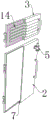
FIG. 1 is a schematic structural view of the overall structure of the present invention;
FIG. 2 is a schematic view of the internal structure of the overall structure of the present invention;
FIG. 3 is an exploded view of the overall structure of the present invention;
FIG. 4 is a sectional view of the main cabinet door and the heat dissipating cabinet door of the present invention;
fig. 5 is a sectional view of the cabinet housing of the present invention.
In the drawings, the components represented by the respective reference numerals are listed below:
1. a cabinet housing; 2. a main cabinet door; 3. a heat dissipation cabinet door; 4. a first vacuum valve; 5. a second vacuum valve; 6. a partition plate; 7. a door panel vacuum cavity; 8. a cabinet shell vacuum cavity; 9. a sound absorbing material; 10. a water-cooled heat dissipation pipeline; 11. a water outlet; 12. a water inlet; 13. a silent cooling fan; 14. a vent hole; 15. fixing a support frame; 16. and fixing the bottom plate.
Detailed Description
The technical solutions in the embodiments of the present invention will be described clearly and completely with reference to the accompanying drawings in the embodiments of the present invention, and it is obvious that the described embodiments are only some embodiments of the present invention, not all embodiments. Based on the embodiments of the present invention, all other embodiments obtained by a person of ordinary skill in the art without creative efforts belong to the protection scope of the present invention.
Referring to fig. 1-5, the present invention relates to a transformer noise-insulation cabinet, which comprises a cabinet housing 1, wherein the front lower end of the cabinet housing 1 is rotatably connected to a main cabinet door 2, the front upper end of the cabinet housing 1 is rotatably connected to a heat-dissipation cabinet door 3, and a handle is disposed on one side of the main cabinet door 2 and the heat-dissipation cabinet door 3, so as to open the main cabinet door 2 and the heat-dissipation cabinet door 3.
Water-cooling heat dissipation pipelines 10 are further fixed on two sides of the interior of the cabinet shell 1, the water-cooling heat dissipation pipelines 10 are attached to the sound absorption material 9, a water outlet 11 is formed in one end of each water-cooling heat dissipation pipeline 10, and a water inlet 12 is formed in the other end of each water-cooling heat dissipation pipeline 10;
1 lower extreme of cabinet casing is fixed with fix the support frame 15, the lower extreme of fix the support frame 15 is fixed with two PMKD 16, two PMKD 16 are inside to be seted up the mounting hole that quantity position is the same, traditional placing means of comparing makes the device fix with ground through PMKD 16, make the produced vibrations of transformer can stably conduct and advance ground, reduce one of the noise source, cabinet casing 1, fix the support frame 15 and PMKD 16 and pass through welded connection fixed, make it more firm.
One specific application of this embodiment is: when the cabinet body is used, air in a door plate vacuum cavity 7 and a cabinet shell vacuum cavity 8 on the inner walls of a cabinet shell 1 and a main cabinet door 2 is extracted through a first vacuum valve 4 and a second vacuum valve 5, so that the interior of the door plate vacuum cavity 7 and the interior of the cabinet shell vacuum cavity 8 are vacuumized, sound-absorbing materials 9 are fixed on two sides and the lower end of the interior of the cabinet shell 1, noise generated when a transformer works in the cabinet shell 1 is firstly absorbed and weakened by the sound-absorbing materials 9, then the interior of the cabinet shell 1 and the interior of the main cabinet door 2 are vacuumized in a large area, sound cannot be transmitted in vacuum, the area of media required by sound transmission is greatly reduced to further weaken the residual noise, vibration generated when the internal transformer works is transmitted to the ground to be absorbed by fixing a fixing bottom plate 16 at the lower end of the cabinet shell 1 and the ground, and noise generated by vibration is reduced, the noise insulation effect of the transformer is achieved through multiple sound insulation and noise reduction designs;
the heat generated by the transformer in the cabinet shell 1 is taken away through the water flow flowing in the water-cooling heat dissipation pipeline 10, so that the heat dissipation and cooling effects are better, the noise generated by heat dissipation is correspondingly reduced, and the high-temperature gas generated by the transformer in the cabinet shell 1 is extracted through the silent heat dissipation fan 13 and discharged through the vent hole 14, so that the heat dissipation effect is achieved.
In the description herein, references to the description of "one embodiment," "an example," "a specific example," etc., mean that a particular feature, structure, material, or characteristic described in connection with the embodiment or example is included in at least one embodiment or example of the invention. In this specification, the schematic representations of the terms used above do not necessarily refer to the same embodiment or example. Furthermore, the particular features, structures, materials, or characteristics described may be combined in any suitable manner in any one or more embodiments or examples.
The preferred embodiments of the present invention disclosed above are intended only to help illustrate the present invention. The preferred embodiments are not intended to be exhaustive or to limit the invention to the precise embodiments disclosed. Obviously, many modifications and variations are possible in light of the above teaching. The embodiments were chosen and described in order to best explain the principles of the invention and its practical applications, to thereby enable others skilled in the art to best understand the invention for and utilize the invention. The present invention is limited only by the claims and their full scope and equivalents.
Claims (6)
1. The utility model provides a transformer noise insulation cabinet, includes cabinet casing (1), its characterized in that: the cabinet is characterized in that the main cabinet door (2) is rotatably connected to the front lower end of the cabinet shell (1), the heat dissipation cabinet door (3) is rotatably connected to the front upper end of the cabinet shell (1), a first vacuum valve (4) is installed on one side of the cabinet shell (1), a second vacuum valve (5) is installed on one side of the main cabinet door (2), a partition plate (6) is fixed to the inner upper end of the cabinet shell (1), a door panel vacuum cavity (7) is formed in the inner wall of the main cabinet door (2), a cabinet shell vacuum cavity (8) is formed in the inner wall of the cabinet shell (1), sound absorption materials (9) are fixed to the two inner sides and the bottom of the cabinet shell (1), the sound absorption materials (9) are located at the position of the lower end of the partition plate (6), water cooling pipelines (10) are further fixed to the two inner sides of the cabinet shell (1), and the water cooling pipelines (10) are attached to the sound absorption materials (9), a water outlet (11) is formed in one end of the water-cooling heat dissipation pipeline (10), and a water inlet (12) is formed in the other end of the water-cooling heat dissipation pipeline (10);
the utility model discloses a cabinet, including division board (6), heat dissipation cabinet door (3), division board (6) inside is fixed with silence radiator fan (13), a plurality of ventilation holes (14) have been seted up to heat dissipation cabinet door (3) inside, cabinet casing (1) lower extreme is fixed with fixed stay frame (15).
2. A transformer noise-insulated cabinet according to claim 1, characterized in that: handles are arranged on one sides of the main cabinet door (2) and the heat dissipation cabinet door (3).
3. A transformer noise-insulated cabinet according to claim 1, characterized in that: the openings of the plurality of ventilation holes (14) are inclined downwards, and one side of the plurality of ventilation holes (14) with low angle faces outwards and is provided with a dust-shielding cover plate.
4. A transformer noise-insulated cabinet according to claim 1, characterized in that: the sound-absorbing material (9) is made of foamed aluminum.
5. A transformer noise-insulated cabinet according to claim 1, characterized in that: two fixing bottom plates (16) are fixed at the lower ends of the fixing support frames (15), and mounting holes with the same number and positions are formed in the two fixing bottom plates (16).
6. A transformer noise-insulated cabinet according to claim 1, characterized in that: the cabinet shell (1), the fixed support frame (15) and the fixed bottom plate (16) are fixedly connected through welding.
Priority Applications (1)
| Application Number | Priority Date | Filing Date | Title |
|---|---|---|---|
| CN202120146490.1U CN214175845U (en) | 2021-01-20 | 2021-01-20 | Noise insulation cabinet for transformer |
Applications Claiming Priority (1)
| Application Number | Priority Date | Filing Date | Title |
|---|---|---|---|
| CN202120146490.1U CN214175845U (en) | 2021-01-20 | 2021-01-20 | Noise insulation cabinet for transformer |
Publications (1)
| Publication Number | Publication Date |
|---|---|
| CN214175845U true CN214175845U (en) | 2021-09-10 |
Family
ID=77593648
Family Applications (1)
| Application Number | Title | Priority Date | Filing Date |
|---|---|---|---|
| CN202120146490.1U Expired - Fee Related CN214175845U (en) | 2021-01-20 | 2021-01-20 | Noise insulation cabinet for transformer |
Country Status (1)
| Country | Link |
|---|---|
| CN (1) | CN214175845U (en) |
Cited By (1)
| Publication number | Priority date | Publication date | Assignee | Title |
|---|---|---|---|---|
| CN118299169A (en) * | 2024-06-05 | 2024-07-05 | 大连连德电力电子科技有限公司 | Anti-theft noise-reduction transformer |
-
2021
- 2021-01-20 CN CN202120146490.1U patent/CN214175845U/en not_active Expired - Fee Related
Cited By (1)
| Publication number | Priority date | Publication date | Assignee | Title |
|---|---|---|---|---|
| CN118299169A (en) * | 2024-06-05 | 2024-07-05 | 大连连德电力电子科技有限公司 | Anti-theft noise-reduction transformer |
Similar Documents
| Publication | Publication Date | Title |
|---|---|---|
| CN209875500U (en) | Low noise fan and range hood | |
| CN106089417A (en) | A kind of small size ultra-quiet type diesel generating set | |
| CN206190400U (en) | Hush air wind cooling type internal combustion engine generating set | |
| JP4410698B2 (en) | Electronic equipment storage box | |
| CN102629739A (en) | Thin noise reduction structure capable of naturally ventilating for indoor substation | |
| CN118148768A (en) | Mute power station | |
| CN210509384U (en) | A low-noise container diesel generator set for data center | |
| CN205638659U (en) | Advance air exhausting structure and have into air exhausting structure's unit | |
| CN111456850A (en) | Power supply sound insulation device of diesel generator | |
| CN215860465U (en) | Partition heat dissipation and noise reduction structure of diesel generating set | |
| CN223344153U (en) | A low-noise box for diesel generator sets | |
| CN110749206A (en) | A mixed-flow low-noise closed cooling tower for DC power transmission | |
| CN210374015U (en) | Muffler assembly suitable for ventilation system | |
| CN210486569U (en) | Mechanical ventilation cooling tower | |
| CN119694719A (en) | High-efficiency heat dissipation, low noise, safe and environmentally friendly outdoor dry-type reactor or transformer | |
| JP4276615B2 (en) | Electronic equipment storage box | |
| CN212583819U (en) | Ultra-silent low-noise generator set | |
| WO2023226777A1 (en) | Blower | |
| CN213064087U (en) | Muffler and air cooler using the same | |
| CN211782865U (en) | A mixed-flow low-noise closed cooling tower for DC power transmission | |
| CN208349875U (en) | A kind of cooling tower noise reducing apparatus | |
| CN209802129U (en) | Cooling tower with silencer | |
| CN117995149A (en) | Noise reduction equipment, heat dissipation devices and energy storage devices | |
| CN221403971U (en) | Cooling tower noise elimination structure and cooling tower | |
| CN223707761U (en) | Power cabin cover and ventilation sound insulation shrouding structure thereof |
Legal Events
| Date | Code | Title | Description |
|---|---|---|---|
| GR01 | Patent grant | ||
| GR01 | Patent grant | ||
| CF01 | Termination of patent right due to non-payment of annual fee | ||
| CF01 | Termination of patent right due to non-payment of annual fee |
Granted publication date: 20210910 |