CN214164724U - Hybrid power device of electric vehicle - Google Patents
Hybrid power device of electric vehicle Download PDFInfo
- Publication number
- CN214164724U CN214164724U CN202023316020.XU CN202023316020U CN214164724U CN 214164724 U CN214164724 U CN 214164724U CN 202023316020 U CN202023316020 U CN 202023316020U CN 214164724 U CN214164724 U CN 214164724U
- Authority
- CN
- China
- Prior art keywords
- buffer
- support
- base
- damping
- hybrid
- Prior art date
- Legal status (The legal status is an assumption and is not a legal conclusion. Google has not performed a legal analysis and makes no representation as to the accuracy of the status listed.)
- Active
Links
- 239000000872 buffer Substances 0.000 claims abstract description 34
- 239000007853 buffer solution Substances 0.000 claims abstract description 33
- 230000035939 shock Effects 0.000 claims abstract description 24
- 238000010521 absorption reaction Methods 0.000 claims abstract description 8
- 238000013016 damping Methods 0.000 claims description 33
- 230000003139 buffering effect Effects 0.000 claims description 15
- 239000006096 absorbing agent Substances 0.000 description 5
- 238000001125 extrusion Methods 0.000 description 2
- 230000009286 beneficial effect Effects 0.000 description 1
- 230000009194 climbing Effects 0.000 description 1
- 238000010586 diagram Methods 0.000 description 1
- 230000000694 effects Effects 0.000 description 1
- 238000000034 method Methods 0.000 description 1
- 239000000243 solution Substances 0.000 description 1
Images


Landscapes
- Electric Propulsion And Braking For Vehicles (AREA)
- Arrangement Or Mounting Of Propulsion Units For Vehicles (AREA)
- Vibration Prevention Devices (AREA)
Abstract
The utility model discloses an electric vehicle hybrid device, which relates to the technical field of electric vehicle auxiliary equipment, and comprises a hybrid device and a buffer base, wherein a buffer plate is arranged above the buffer base, the hybrid device is fixedly arranged on the upper surface of the buffer plate, the buffer plate is connected with the buffer base in a sliding way, the left and right sides of the lower surface of the buffer plate are symmetrically provided with buffer arcs, the bottom end of each buffer arc is fixedly connected with a support plate, the left and right sides of the upper surface of the buffer base are symmetrically provided with supports, support rods are symmetrically arranged between the supports, when the hybrid device vibrates up and down, the hybrid device extrudes the buffer arcs through the buffer plate to shrink, the buffer arcs convert the external acting force into elastic force, thus realizing preliminary shock absorption, the shock absorption support extrudes the shock absorption spring to stretch and shrink, the shock absorption spring converts the external acting force into elastic force, realizes secondary shock absorption, and effectively protects the hybrid device, avoid damaging the internal parts due to excessive vibration.
Description
Technical Field
The utility model relates to an electric motor car auxiliary assembly technical field specifically is an electric motor car hybrid device.
Background
Electric vehicles, namely electric drive vehicles, are also known as electric drive vehicles. Electric vehicles are classified into alternating current electric vehicles and direct current electric vehicles. Generally, an electric vehicle is a vehicle that uses a battery as an energy source, and converts electric energy into mechanical energy through a controller, a motor and other components to move so as to control the current and change the speed.
In the use, because the electric motor car adopts pure electric drive structure, its battery capacity is limited, consequently the time of endurance is shorter, can bring inconvenience for the user when the in-process electric power that traveles is not enough, and power is not enough, and the climbing ability is relatively poor, influences the driving effect, prior art uses hybrid power equipment to provide sufficient power usually, but the hybrid power equipment bottom is not provided with buffer gear, damages internals very easily when the road surface walking of jolting.
SUMMERY OF THE UTILITY MODEL
An object of the utility model is to provide an electric motor car hybrid device to solve the problem that proposes among the above-mentioned background art.
In order to achieve the above object, the utility model provides a following technical scheme:
the utility model provides an electric motor car hybrid device, includes hybrid equipment and buffer base, the top sets up the buffer board in the buffer base, hybrid equipment fixed mounting is on the buffer board upper surface, buffer board and buffer base sliding connection, buffer board lower surface left and right sides symmetry sets up the buffering circular arc, terminal and extension board fixed connection in buffering circular arc bottom, buffer base upper surface left and right sides symmetry sets up the support, the left and right sides the symmetry sets up branch between the support, both ends symmetry sets up damping spring about branch, the left and right sides one end fixed connection damping support that damping spring is close to each other, damping support and branch sliding connection, damping support swing joint shock attenuation pole, both sides damping support's one end and extension board swing joint are kept away from to the shock attenuation pole.
As a further aspect of the present invention: fastening bolts are symmetrically arranged at the left end and the right end of the buffer base, and the buffer base is detachably and fixedly connected with the frame through the fastening bolts.
As a further aspect of the present invention: hybrid power equipment below fixed connection base, the base can dismantle fixed connection with the buffer board.
As a further aspect of the present invention: the buffer base is characterized in that a first limiting groove is formed in the inner side wall above the left end and the right end of the buffer base, a first limiting seat is symmetrically and fixedly connected with the left end and the right end of the buffer plate, and the first limiting seat is slidably connected with the first limiting groove.
As a further aspect of the present invention: the upper surface of the buffer base is symmetrically provided with a second limiting groove, the lower part of the damping support is fixedly connected with a second limiting seat, and the second limiting seat is slidably connected with the second limiting groove.
As a further aspect of the present invention: the buffer base is characterized in that positioning rods are symmetrically arranged on the left side and the right side of the upper surface of the buffer base, return springs are arranged on the outer sides of the positioning rods, movable seats are symmetrically and fixedly connected to the left end and the right end of the support plate, and the movable seats are connected with the positioning rods in a sliding mode.
Compared with the prior art, the beneficial effects of the utility model are that: the utility model provides an electric motor car hybrid device, when hybrid device vibrates from top to bottom, hybrid device passes through buffer board extrusion buffering circular arc shrink, and the buffering circular arc turns into the elastic force with external acting force, realizes preliminary shock attenuation, and the buffering circular arc passes through extension board and shock attenuation pole promotion damping support and controls about branch surface level, and damping support extrusion damping spring is tensile and shrink, damping spring turns into the elastic force with external acting force, realizes the shock attenuation once more, effectively protects hybrid device, avoids vibrating the too big damage internals.
Drawings
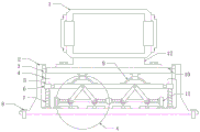
Fig. 1 is a schematic structural diagram of a hybrid power device of an electric vehicle.
Fig. 2 is an enlarged schematic structural view of a hybrid power device of an electric vehicle at a point a in fig. 1.
Fig. 3 is a schematic structural view of a return spring in a hybrid device of an electric vehicle.
In the figure: 1-a hybrid power plant; 2-a buffer base; 3-a first limiting seat; 4-a first limiting groove; 5-positioning the rod; 6-a movable seat; 7-a return spring; 8-fastening bolts; 9-buffering the arc; 10-a buffer plate; 11-a support; 12-a base; 13-a strut; 14-a shock mount; 15-a second limiting seat; 16-a second limiting groove; 17-a damping spring; 18-a shock-absorbing rod; 19-support plate.
Detailed Description
The technical solution of the present patent will be described in further detail with reference to the following embodiments.
Example 1
Referring to fig. 1-3, an electric vehicle hybrid power device includes a hybrid power device 1 and a buffer base 2, a buffer plate 10 is disposed at the upper portion of the interior of the buffer base 2, the hybrid power device 1 is fixedly mounted on the upper surface of the buffer plate 10, the buffer plate 10 is slidably connected with the buffer base 2, buffer arcs 9 are symmetrically disposed at the left and right sides of the lower surface of the buffer plate 10, the bottom end of each buffer arc 9 is fixedly connected with a support plate 19, supports 11 are symmetrically disposed at the left and right sides of the upper surface of the buffer base 2, support rods 13 are symmetrically disposed between the supports 11 at the left and right sides, damping springs 17 are symmetrically disposed at the left and right ends of each support rod 13, one ends of the damping springs 17 at the left and right sides close to each other are fixedly connected with a damping support 14, the damping support 14 is slidably connected with the support rods 13, the damping support 14 is movably connected with a damping rod 18, both sides shock absorber rod 18 keeps away from shock absorber 14's one end and extension board 19 swing joint, when hybrid device 1 vibrates from top to bottom, hybrid device 1 extrudes buffering circular arc 9 through buffer board 10 and contracts, buffering circular arc 9 turns into the elastic force with external force, realizes preliminary shock attenuation, buffering circular arc 9 passes through extension board 19 and shock absorber rod 18 and promotes shock absorber 14 and remove about branch 13 surface level, shock absorber support 14 extrudes damping spring 17 and stretches and contract, damping spring 17 turns into the elastic force with external force, realizes shock attenuation once more.
Further, in order to fix the buffer base 2, in this embodiment, the fastening bolts 8 are symmetrically arranged at the left end and the right end of the buffer base 2, and the buffer base 2 is detachably and fixedly connected with the frame through the fastening bolts 8.
Further, in order to facilitate the disassembly and assembly of the hybrid power device 1, in this embodiment, a base 12 is fixedly connected below the hybrid power device 1, and the base 12 is detachably and fixedly connected with the buffer plate 10.
Further, in order to improve the stability of vibration about buffer board 10, in this embodiment, buffer base 2 left and right both ends top inside wall sets up spacing groove one 4, buffer board 10 left and right both ends symmetry fixed connection spacing seat one 3, spacing seat one 3 and spacing groove one 4 sliding connection.
Further, in order to improve the stability of the shock absorption support 14 moving left and right in the horizontal direction, in this embodiment, the second limit groove 16 is symmetrically arranged on the upper surface of the buffer base 2, the second limit seat 15 is fixedly connected to the lower side of the shock absorption support 14, and the second limit seat 15 is slidably connected to the second limit groove 16.
Example 2
Referring to fig. 1-3, on the basis of embodiment 1, in order to improve the stability of the support plate 19 moving up and down in the vertical direction, positioning rods 5 are symmetrically arranged on the left and right sides of the upper surface of the buffer base 2, return springs 7 are arranged outside the positioning rods 5, movable seats 6 are symmetrically and fixedly connected to the left and right ends of the support plate 19, and the movable seats 6 are slidably connected to the positioning rods 5.
The utility model discloses a theory of operation is: the utility model provides an electric motor car hybrid device, when hybrid device 1 vibrates from top to bottom, hybrid device 1 extrudees buffering circular arc 9 through buffer board 10 and contracts, buffering circular arc 9 turns into the elastic force with external force, realizes preliminary shock attenuation, buffering circular arc 9 passes through extension board 19 and shock attenuation pole 18 and promotes damping support 14 and controls about branch 13 surface level, damping support 14 extrudes damping spring 17 and stretches and the shrink, damping spring 17 turns into the elastic force with external force, realizes the shock attenuation once more.
Although the preferred embodiments of the present patent have been described in detail, the present patent is not limited to the above embodiments, and various changes can be made without departing from the spirit of the present patent within the knowledge of those skilled in the art.
Claims (6)
1. The utility model provides an electric motor car hybrid device, includes hybrid equipment (1) and buffer base (2), its characterized in that, the top sets up buffer board (10) in buffer base (2), hybrid equipment (1) fixed mounting is on buffer board (10) upper surface, buffer board (10) and buffer base (2) sliding connection, buffer board (10) lower surface left and right sides symmetry sets up buffering circular arc (9), terminal and the extension board (19) fixed connection in buffering circular arc (9) bottom, buffer base (2) upper surface left and right sides symmetry sets up support (11), the left and right sides symmetry sets up branch (13) between support (11), both ends symmetry sets up damping spring (17) about branch (13), the left and right sides one end fixed connection damping support (14) that damping spring (17) are close to each other, the damping support (14) is connected with the support rod (13) in a sliding mode, the damping support (14) is movably connected with a damping rod (18), and the damping rods (18) on two sides are movably connected with the support plate (19) at the end, far away from the damping support (14), of the damping rod (18).
2. The hybrid power device of the electric vehicle as claimed in claim 1, wherein the left and right ends of the buffer base (2) are symmetrically provided with fastening bolts (8), and the buffer base (2) is detachably and fixedly connected with the vehicle frame through the fastening bolts (8).
3. An electric vehicle hybrid arrangement according to claim 1 or 2, characterized in that a base (12) is fixedly connected below the hybrid device (1), and the base (12) is detachably and fixedly connected with the bumper plate (10).
4. The hybrid power device of the electric vehicle as claimed in claim 3, wherein the inner side wall of the buffer base (2) is provided with a first limiting groove (4) above the left end and the right end, the buffer plate (10) is fixedly connected with the first limiting seat (3) symmetrically at the left end and the right end, and the first limiting seat (3) is slidably connected with the first limiting groove (4).
5. The hybrid power device of the electric vehicle as claimed in claim 4, wherein the upper surface of the buffering base (2) is symmetrically provided with a second limiting groove (16), the second limiting seat (15) is fixedly connected below the shock absorption support (14), and the second limiting seat (15) is slidably connected with the second limiting groove (16).
6. The hybrid power device of the electric vehicle as claimed in claim 5, wherein the left and right sides of the upper surface of the buffering base (2) are symmetrically provided with positioning rods (5), the outer side of each positioning rod (5) is provided with a return spring (7), the left and right ends of the support plate (19) are symmetrically and fixedly connected with the movable seat (6), and the movable seat (6) is slidably connected with the positioning rods (5).
Priority Applications (1)
| Application Number | Priority Date | Filing Date | Title |
|---|---|---|---|
| CN202023316020.XU CN214164724U (en) | 2020-12-31 | 2020-12-31 | Hybrid power device of electric vehicle |
Applications Claiming Priority (1)
| Application Number | Priority Date | Filing Date | Title |
|---|---|---|---|
| CN202023316020.XU CN214164724U (en) | 2020-12-31 | 2020-12-31 | Hybrid power device of electric vehicle |
Publications (1)
| Publication Number | Publication Date |
|---|---|
| CN214164724U true CN214164724U (en) | 2021-09-10 |
Family
ID=77611528
Family Applications (1)
| Application Number | Title | Priority Date | Filing Date |
|---|---|---|---|
| CN202023316020.XU Active CN214164724U (en) | 2020-12-31 | 2020-12-31 | Hybrid power device of electric vehicle |
Country Status (1)
| Country | Link |
|---|---|
| CN (1) | CN214164724U (en) |
-
2020
- 2020-12-31 CN CN202023316020.XU patent/CN214164724U/en active Active
Similar Documents
| Publication | Publication Date | Title |
|---|---|---|
| CN107123757B (en) | A kind of new energy car battery protection damping | |
| CN110212127B (en) | Lithium battery fixing and mounting device of new energy electric vehicle | |
| CN108061125B (en) | A kind of working method of automobile shock absorber power generation mechanism based on hydraulic pipe | |
| CN108482089A (en) | A kind of electric automobile lithium battery group damping device | |
| CN110861459B (en) | Suspension structure for distributed driving | |
| CN208428918U (en) | A kind of automobile-used damping chassis of new energy 4 wheel driven | |
| CN208580784U (en) | A kind of batteries of electric automobile intermediate support assembly | |
| CN203939908U (en) | The bump leveller that rigidity is adjustable | |
| CN101638055A (en) | Device for generating electricity by vibration energy generated when vehicle travels | |
| CN115864722A (en) | Generator shake damping device | |
| CN207328034U (en) | A kind of damping device of electric car | |
| CN208986065U (en) | A kind of fixation device of automobile batteries case | |
| KR101238278B1 (en) | Shock absorber for vehicle including linear generator | |
| CN213892148U (en) | Damping device that new energy automobile used | |
| CN216045183U (en) | Shock-absorbing device for driving wheel of pile driver | |
| CN109065781A (en) | A kind of batteries of electric automobile intermediate support assembly | |
| CN108644278A (en) | A kind of damping | |
| CN216530499U (en) | Cable connecting device for electric power construction | |
| CN216120585U (en) | New energy automobile group battery fixed bolster | |
| CN215552404U (en) | Electromagnetic composite suspension damping system | |
| CN220172265U (en) | Battery protection device of electric tricycle | |
| CN216056553U (en) | Motor support with shock-absorbing function | |
| CN218453421U (en) | Novel high-power off-road electric vehicle | |
| CN223894846U (en) | A permanent magnet-assisted energy recovery shock absorber for automobiles | |
| CN219394568U (en) | Buffering and damping base for generator of photovoltaic power station |
Legal Events
| Date | Code | Title | Description |
|---|---|---|---|
| GR01 | Patent grant | ||
| GR01 | Patent grant | ||
| PE01 | Entry into force of the registration of the contract for pledge of patent right | ||
| PE01 | Entry into force of the registration of the contract for pledge of patent right |
Denomination of utility model: Electric vehicle hybrid power device Effective date of registration: 20211210 Granted publication date: 20210910 Pledgee: Bank of Dezhou Limited by Share Ltd. Qihe branch Pledgor: Shandong Yuehe New Energy Technology Co.,Ltd. Registration number: Y2021980014575 |