Efficient concrete vibrator
Technical Field
The utility model relates to a construction equipment technical field specifically is an efficient concrete vibrator.
Background
When the concrete is used for pouring the member, air bubbles in the concrete must be removed, the concrete can be more compactly combined, the phenomena of honeycomb pitted surface and the like of the concrete are eliminated, the strength of the concrete member is improved, the quality of the concrete member is ensured, generally, the manual operation is directly trampled on the concrete, the vibration rod is held by hands and inserted into the concrete for work, therefore, when the personnel trample, air enters the inside of the concrete again, and the vibration rod can be manually operated to possibly eliminate the uneven air bubbles, and therefore, the equipment is needed to be improved.
SUMMERY OF THE UTILITY MODEL
An object of the utility model is to provide an efficient concrete vibrator to solve the problem of proposing among the above-mentioned background art.
In order to achieve the above object, the utility model provides a following technical scheme: a high-efficiency concrete vibration device comprises a movable supporting seat, wherein a transmission set is fixedly connected to one side inside the movable supporting seat, a limiter is fixedly welded at the top end of one side of the transmission set, the transmission set comprises an insertion rod, a fixed supporting block, a first bearing, a connecting rod, a vibration rod, a transmission belt, a gear and a motor, the insertion rod is fixedly welded at the center of one side of the fixed supporting block, the vibration rod is inserted into the fixed supporting block, the first bearing is fixedly welded at the center of the side end, away from the insertion rod, of the fixed supporting block, the connecting rod is fixedly connected inside the first bearing, the transmission belt is fixedly connected to one end, away from the first bearing, of the connecting rod, the gear is symmetrically meshed inside the transmission belt, the motor is fixedly connected to the side end of the gear, the limiter comprises a conveying cavity, a pull rod, a spring and a limiting block, the utility model discloses a conveying device, including conveying chamber, pull pole, stopper, movable supporting seat, cleaning brush, handle, second bearing, sliding key, spout base, handle symmetry fixed welding, sliding key symmetry fixed welding is at the both ends of supporting baseplate, the fixed welding of sliding key symmetry is at the bottom both ends of supporting baseplate, the inside one end of conveying chamber, spring fixed connection is between conveying chamber and stopper, the movable supporting seat includes rotation groove, supporting baseplate, cleaning brush, handle, second bearing, sliding key, spout base and support curb plate, rotation groove is seted up in inside one side of supporting baseplate, cleaning brush symmetry fixed connection is at the one end center of supporting baseplate, support curb plate fixed welding is at the inside opposite side of supporting baseplate, just the symmetrical fixed mounting of second bearing is at the side both ends of supporting the curb plate, handle symmetry fixed welding is at the both ends of supporting baseplate, sliding key symmetry fixed welding is at the bottom both ends of supporting baseplate, spout base symmetry slip joint is on the sliding key.
Preferably, the inserted bar is clamped inside the rotating groove in a sliding manner, and the gears are symmetrically and fixedly connected inside the second bearing.
Preferably, the cleaning brush is made of nylon.
Preferably, the top of the side end of the vibration rod is provided with a clamping groove matched with the limiting block.
Preferably, the bottom end of the supporting side plate is arranged in a suspended state, and the transmission belt drives the connecting rod to pass through the bottom end of the supporting side plate when rotating.
Preferably, the transmission belt drives the rear end of the vibration rod to be in contact with the cleaning brush when rotating.
Compared with the prior art, the beneficial effects of the utility model are as follows:
the utility model discloses an installation transmission group, transmission group is used for the work of even vibrations, through the fixed stay fixed welding at the side of first bearing, first bearing fixed welding is on the connecting rod, can be with connecting rod fixed connection at the side of drive belt, again with motor circular telegram start, make and to drive the drive belt and rotate, and the drive belt is when rotating, can drive the connecting rod, first bearing and fixed stay rotate simultaneously, peg graft in the inside of fixed stay through the vibrant stick, can be connected one end of vibrant stick with external vibrator, make and drive the reciprocal downward and fore-and-aft work of vibrant stick through the drive belt, thereby can be with the even vibrations of concrete, thereby can improve the quality of concrete, and the inserted bar fixed welding is in the center of one end of fixed stay, the rotation groove is seted up in the inside one side of supporting baseplate, can be with the one end slip joint of inserted bar in the rotation groove, thereby assisting in supporting the vibration rod to complete the vibration work, avoiding the vibration rod from deviating during the work, fixedly welding the vibration rod at one side of the fixed supporting block through the conveying cavity, respectively clamping the pull rod and the limiting block in the conveying cavity in a sliding manner, fixedly welding the pull rod and the limiting block between the conveying cavity and the limiting block through the spring, arranging a clamping groove matched with the limiting block at the top of the side end of the vibration rod, driving the limiting block to be inserted in the vibration rod through the tension of the spring, avoiding the vibration rod from falling off from the inside of the fixed supporting block when being inserted into the concrete, symmetrically and fixedly connecting the vibration rod at the center of one end of the supporting bottom plate through the cleaning brush, contacting the rear end of the vibration rod with the cleaning brush when moving, cleaning the rear end of the vibration rod through the nylon material of the cleaning brush, symmetrically and fixedly welding the vibration rod at two sides of the bottom end of the supporting bottom plate through the sliding key, can with the inside of feather key symmetry slip joint at the spout base for the supporting baseplate can be along rectilinear movement on the spout base, and through the fixed welding of handle symmetry at the both ends of supporting baseplate, make but convenient to use person remove the supporting baseplate, through supporting curb plate fixed welding in inside one side of supporting baseplate, and the bottom of supporting the curb plate is unsettled state setting, make and to allow the drive belt to drive the connecting rod and pass through from the bottom that supports the curb plate.
Drawings
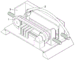
FIG. 1 is a schematic view of the main structure of the present invention;
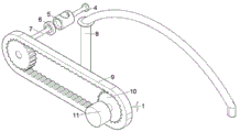
FIG. 2 is a schematic view of the structure of the transmission set of the present invention;
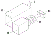
FIG. 3 is a schematic view of the stopper of the present invention;
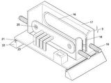
fig. 4 is a schematic view of the structure of the movable supporting seat of the present invention.
In the figure: 1-transmission group, 2-limiter, 3-mobile support seat, 4-inserted rod, 5-fixed support block, 6-first bearing, 7-connecting rod, 8-vibration rod, 9-transmission belt, 10-gear, 11-motor, 12-conveying cavity, 13-drawing rod, 14-spring, 15-limiting block, 16-rotation groove, 17-supporting bottom plate, 18-cleaning brush, 19-handle, 20-second bearing, 21-sliding key, 22-sliding groove base and 23-supporting side plate.
Detailed Description
The technical solutions in the embodiments of the present invention will be described clearly and completely with reference to the accompanying drawings in the embodiments of the present invention, and it is obvious that the described embodiments are only some embodiments of the present invention, not all embodiments. Based on the embodiments in the present invention, all other embodiments obtained by a person skilled in the art without creative work belong to the protection scope of the present invention.
Referring to fig. 1-4, the present invention provides an embodiment: the utility model provides an efficient concrete vibrator, including the movable support seat 3, the inside one side fixedly connected with transmission group 1 of movable support seat 3, the fixed welding in one side top of transmission group 1 has stopper 2, transmission group 1 includes inserted bar 4, fixed support block 5, first bearing 6, connecting rod 7, vibrating spear 8, drive belt 9, gear 10 and motor 11, inserted bar 4 fixed welding is in one side center of fixed support block 5, vibrating spear 8 pegs graft in the inside of fixed support block 5, first bearing 6 fixed welding is in the side center that fixed support block 5 deviates from inserted bar 4, connecting rod 7 fixed connection is in the inside of first bearing 6, drive belt 9 fixed connection is in the one end that connecting rod 7 deviates from first bearing 6, gear 10 symmetry gear engagement is in the inside of drive belt 9, motor 11 fixed connection is at the side of gear 10, stopper 2 includes transport chamber 12, the fixed connection is organized 1, the fixed connection of one side of transmission chamber 12, The device comprises a pull rod 13, a spring 14 and a limiting block 15, wherein the pull rod 13 is inserted into one end of the interior of a conveying cavity 12 in a sliding manner, the limiting block 15 is fixedly welded at the end head of one end of the pull rod 13, the spring 14 is fixedly connected between the conveying cavity 12 and the limiting block 15, a movable supporting seat 3 comprises a rotating groove 16, a supporting bottom plate 17, a cleaning brush 18, a handle 19, a second bearing 20, a sliding key 21, a sliding groove base 22 and a supporting side plate 23, the rotating groove 16 is formed in one side of the interior of the supporting bottom plate 17, the cleaning brush 18 is symmetrically and fixedly connected to the center of one end of the supporting bottom plate 17, the supporting side plate 23 is fixedly welded at the other side of the interior of the supporting bottom plate 17, and the second bearings 20 are symmetrically and fixedly installed at two ends of the side surface of the supporting side plate 23, the handles 19 are symmetrically and fixedly welded at two ends of the supporting bottom plate 17, the sliding keys 21 are symmetrically and fixedly welded at two ends of the bottom of the supporting bottom plate 17, and the sliding groove bases 22 are symmetrically and slidably clamped on the sliding keys 21.
The inserted link 4 is slidably clamped inside the rotating groove 16, the gear 10 is symmetrically and fixedly connected inside the second bearing 20, the cleaning brush 18 is made of nylon, the top of the side end of the vibrating rod 8 is provided with a clamping groove matched with the limiting block 15, the bottom end of the supporting side plate 23 is arranged in a suspended state, the transmission belt 9 drives the connecting rod 7 to pass through the bottom end of the supporting side plate 23 when rotating, the transmission belt 9 drives the rear end of the vibrating rod 8 to contact with the cleaning brush 18 when rotating, the transmission set 1 is used for uniform vibration work, the transmission set is fixedly welded at the side end of the first bearing 6 through the fixed supporting block 5, the first bearing 6 is fixedly welded on the connecting rod 7, the connecting rod 7 can be fixedly connected at the side end of the transmission belt 9, the motor 11 is electrified and started, so that the transmission belt 9 can be driven to rotate, and when the transmission belt 9 rotates, the connecting rod 7 can be driven, the first bearing 6 and the fixed supporting block 5 can rotate simultaneously, the vibrating rod 8 is inserted into the fixed supporting block 5, one end of the vibrating rod 8 can be connected with an external vibrator, so that the vibrating rod 8 is driven to work downwards and forwards in a reciprocating manner through the driving belt 9, the concrete can be uniformly vibrated, the quality of the concrete can be improved, the inserting rod 4 is fixedly welded at the center of one end of the fixed supporting block 5, the rotating groove 16 is formed in one side of the inner part of the supporting bottom plate 17, one end of the inserting rod 4 can be slidably clamped in the rotating groove 16, the vibrating rod 8 can be supported in an auxiliary mode to complete the vibrating work, the phenomenon that the vibrating rod 8 deflects when in work can be avoided, the vibrating rod is fixedly welded at one side of the fixed supporting block 5 through the conveying cavity 12, the pulling rod 13 and the limiting block 15 are respectively clamped in the conveying cavity 12 in a sliding manner, the vibrating rod is fixedly welded between the conveying cavity 12 and the limiting block 15 through the spring 14, a clamping groove matched with the limiting block 15 is formed in the top of the side end of the vibrating rod 8, through the tension of the spring 14, the limiting block 15 can be driven to be inserted into the vibration rod 8, thereby preventing the vibration rod 8 from falling off from the inside of the fixed supporting block 5 when being inserted into the concrete, the cleaning brush 18 is symmetrically and fixedly connected to the center of one end of the supporting bottom plate 17, the rear end of the vibration rod 8 is contacted with the cleaning brush 18 when moving, the rear end of the vibration rod 8 can be cleaned by using the cleaning brush 18 made of nylon, the sliding key 21 is symmetrically and fixedly welded on the two sides of the bottom end of the supporting bottom plate 17, the sliding key 21 can be symmetrically and slidably clamped inside the chute base 22, the supporting bottom plate 17 can move on the chute base 22 along a straight line, and the handles 19 are symmetrically and fixedly welded on the two ends of the supporting bottom plate 17, so that a user can conveniently move the supporting bottom plate 17, the supporting side plate 23 is fixedly welded on one side of the inside of the supporting bottom plate 17, and the bottom ends of the supporting side plates 23 are disposed in a suspended state so that the driving belt 9 can be allowed to drive the connecting rods 7 to pass through the bottom ends of the supporting side plates 23.
The working principle is as follows: the user erects the device at two ends of concrete to be vibrated in advance, then connects one end of the vibrating rod 8 with an external vibrator, meanwhile, the other end of the vibrating rod 8 is inserted in the fixed supporting block 5, a clamping groove matched with the limiting block 15 is formed at one end of the vibrating rod 8, the limiting block 15 and the pull-out rod 13 are respectively inserted in the conveying cavity 12 in a sliding manner, the spring 14 is fixedly welded between the conveying cavity 12 and the limiting block 15, the limiting block 15 can be extruded into the clamping groove through the elasticity of the spring 14, so that the vibrating rod 8 can be prevented from falling off from the inside of the fixed supporting block 5 when being inserted into the concrete, meanwhile, the motor 11 is electrified and started, thereby the gear 10 and the transmission belt 9 can be driven to rotate, the first bearing 6 is fixedly connected at the side end of the first bearing 6 through the fixed supporting block 5, the first bearing 6 is fixedly connected at the side end of the connecting rod 7, the connecting rod 7 can be fixedly welded at the side end of the driving belt 9, the driving belt 9 can drive the fixed supporting block 5 to rotate while rotating, so that the purpose of uniformly vibrating the inside of concrete can be realized, the bottom end of the supporting side plate 23 is arranged in a suspended state, so that the driving belt 9 can be allowed to drive the connecting rod 7 to pass through the bottom end of the supporting side plate 23, the connecting rod 7 is fixedly welded at the center of one end of the fixed supporting block 5 through the inserting rod 4, the rotating groove 16 is formed in one side of the inside of the supporting base plate 17, the inserting rod 4 can be slidably inserted into the rotating groove 16, so that the fixed supporting block 5 can be supported in an auxiliary mode to complete the vibration work, the cleaning brush 18 is symmetrically and fixedly connected at the center of one end of the supporting base plate 17, the cleaning brush 18 is made of nylon, when the vibration rod 8 continuously works back and forth, the cleaning brush 18 can be in contact with the concrete stuck on the vibration rod 8, and the concrete can be cleaned, meanwhile, the sliding key 21 is symmetrically welded at the bottom end of the supporting bottom plate 17, the sliding key 21 can be clamped inside the top end of the sliding groove base 22 in a sliding mode, and a user pulls the handle 19, so that the supporting bottom plate 17 can be conveniently moved.
Although embodiments of the present invention have been shown and described, it will be appreciated by those skilled in the art that changes, modifications, substitutions and alterations can be made in these embodiments without departing from the principles and spirit of the invention, the scope of which is defined in the appended claims and their equivalents.