CN214153514U - Switch cabinet for high-voltage equipment - Google Patents
Switch cabinet for high-voltage equipment Download PDFInfo
- Publication number
- CN214153514U CN214153514U CN202022989321.2U CN202022989321U CN214153514U CN 214153514 U CN214153514 U CN 214153514U CN 202022989321 U CN202022989321 U CN 202022989321U CN 214153514 U CN214153514 U CN 214153514U
- Authority
- CN
- China
- Prior art keywords
- dry powder
- cabinet body
- component chamber
- heat
- sliding block
- Prior art date
- Legal status (The legal status is an assumption and is not a legal conclusion. Google has not performed a legal analysis and makes no representation as to the accuracy of the status listed.)
- Active
Links
- 239000000843 powder Substances 0.000 claims abstract description 37
- UGFAIRIUMAVXCW-UHFFFAOYSA-N Carbon monoxide Chemical compound [O+]#[C-] UGFAIRIUMAVXCW-UHFFFAOYSA-N 0.000 claims abstract description 13
- 239000003546 flue gas Substances 0.000 claims abstract description 13
- 230000005540 biological transmission Effects 0.000 claims description 4
- 230000033228 biological regulation Effects 0.000 abstract description 2
- 230000000007 visual effect Effects 0.000 description 10
- 230000017525 heat dissipation Effects 0.000 description 9
- 239000007921 spray Substances 0.000 description 6
- 229940098458 powder spray Drugs 0.000 description 4
- 238000006243 chemical reaction Methods 0.000 description 2
- 230000000694 effects Effects 0.000 description 2
- 238000000034 method Methods 0.000 description 2
- 230000005012 migration Effects 0.000 description 2
- 238000013508 migration Methods 0.000 description 2
- 239000000779 smoke Substances 0.000 description 2
- 229910000831 Steel Inorganic materials 0.000 description 1
- 230000006978 adaptation Effects 0.000 description 1
- 230000009286 beneficial effect Effects 0.000 description 1
- 238000010276 construction Methods 0.000 description 1
- 230000008878 coupling Effects 0.000 description 1
- 238000010168 coupling process Methods 0.000 description 1
- 238000005859 coupling reaction Methods 0.000 description 1
- 230000006870 function Effects 0.000 description 1
- 239000007789 gas Substances 0.000 description 1
- 230000007246 mechanism Effects 0.000 description 1
- 239000002184 metal Substances 0.000 description 1
- 238000005065 mining Methods 0.000 description 1
- 230000008447 perception Effects 0.000 description 1
- 238000010248 power generation Methods 0.000 description 1
- 230000008569 process Effects 0.000 description 1
- 238000005096 rolling process Methods 0.000 description 1
- 239000010959 steel Substances 0.000 description 1
- 239000004753 textile Substances 0.000 description 1
Images


Landscapes
- Fire-Extinguishing By Fire Departments, And Fire-Extinguishing Equipment And Control Thereof (AREA)
Abstract
The utility model discloses a cubical switchboard for high-tension apparatus relates to cubical switchboard technical field, can not carry out the problem of putting out a fire to the condition of a fire the very first time for solving current high-tension apparatus cubical switchboard. The inside in the cabinet body is provided with the component chamber, one side in component chamber is provided with adjusts the chamber, the inside rotation in regulation chamber installs the lead screw, the externally mounted of lead screw has the sliding block, and one side of sliding block extends to the inside in component chamber, one side fixed mounting of sliding block has the dry powder shower nozzle, flue gas temperature sensor is installed to one side of component chamber upper end, and flue gas temperature sensor passes through the screw fixation with the cabinet body, the singlechip is installed to the opposite side of component chamber upper end, the fixed mounting bracket that is provided with in inside in component chamber, the rear end of mounting bracket is provided with the heat-conducting plate.
Description
Technical Field
The utility model relates to a cubical switchboard technical field specifically is a cubical switchboard for high-tension apparatus.
Background
The high-voltage equipment switch cabinet is used for switching on and off, controlling or protecting in power generation, power transmission, power distribution, electric energy conversion and consumption of an electric power system. The high-voltage switch cabinet is an electric appliance product with the working voltage grade of 3.6 kV-550 kV, and comprises a cabinet body and a circuit breaker, wherein the cabinet body comprises a shell, electric appliance elements (including an insulating part), various mechanisms, secondary terminals, connecting wires and the like, and is mainly suitable for various different places such as power plants, transformer substations, petrochemical industry, metallurgical steel rolling, light industrial textiles, industrial and mining enterprises, residential quarters, high-rise buildings and the like.
However, when a fire occurs in the existing high-voltage equipment switch cabinet due to power failure, a worker cannot react and extinguish the fire at the first time, so that the fire is expanded, life safety is threatened, the existing requirements are not met, and the switch cabinet for the high-voltage equipment is provided.
SUMMERY OF THE UTILITY MODEL
An object of the utility model is to provide a cubical switchboard for high-tension apparatus to solve the problem that the high-tension apparatus cubical switchboard that provides in the above-mentioned background art can not put out a fire to the condition of a fire very first time.
In order to achieve the above object, the utility model provides a following technical scheme: the utility model provides a cubical switchboard for high-tension apparatus, includes the cabinet body, the inside of the cabinet body is provided with the component chamber, one side in component chamber is provided with adjusts the chamber, adjust the inside rotation in chamber and install the lead screw, the externally mounted of lead screw has the sliding block, and one side of sliding block extends to the inside in component chamber, one side fixed mounting of sliding block has the dry powder shower nozzle, flue gas temperature sensor is installed to one side of component chamber upper end, and flue gas temperature sensor passes through the screw fixation with the cabinet body, the singlechip is installed to the opposite side of component chamber upper end, the fixed mounting bracket that is provided with in inside in component chamber, the rear end of mounting bracket is provided with the heat-conducting plate.
Preferably, one side of the cabinet body is provided with dry powder high pressure storage tank, and dry powder high pressure storage tank passes through the mount with the cabinet body and fixes, dry powder high pressure storage tank's upper end is provided with the conveyer pipe, the conveyer pipe is close to the one end of dry powder high pressure storage tank and installs the main valve, the upper end of dry powder shower nozzle is provided with the connecting pipe, and the one end of connecting pipe is fixed with the conveyer pipe is sealed, the one end fixed mounting that the connecting pipe is close to the dry powder shower nozzle has the solenoid valve, and the input of solenoid valve and the output electric connection of singlechip.
Preferably, a servo motor is installed below the adjusting cavity, an output shaft of the servo motor is in transmission connection with the lower end of the adjusting cavity through a coupler, and the sliding block is matched with the screw rod.
Preferably, audible and visual alarm is installed to the top of cabinet body one side, and audible and visual alarm and the cabinet body pass through the screw fixation, audible and visual alarm's input and the output electric connection of singlechip.
Preferably, the rear end of heat-conducting plate is provided with radiating fin, and radiating fin is provided with a plurality of, and radiating fin distributes in proper order, radiating fin and heat-conducting plate structure as an organic whole.
Preferably, the four corners of the rear end of the heat conducting plate are respectively provided with a heat radiating fan, and the heat radiating fans and the heat conducting plate are fixed through bolts.
Compared with the prior art, the beneficial effects of the utility model are that:
1. the utility model discloses an internally mounted at the cabinet body has flue gas temperature sensor, flue gas temperature sensor can discern the temperature and the flue gas of the internal portion of cabinet, when inside because of power failure produces the condition of a fire, flue gas temperature sensor can the perception rapidly, to singlechip signals, audible-visual annunciator and solenoid valve are opened simultaneously to the singlechip, audible-visual annunciator can inform the site work personnel to react fast and handle, after opening the solenoid valve, the inside dry powder of dry powder high-pressure storage tank passes through the conveyer pipe and gets into to the connecting pipe, and spray the dry powder to component intracavity portion through the dry powder shower nozzle, thereby realize putting out a fire and rescue in the condition of a fire very first time.
2. The utility model discloses a be provided with the regulation chamber in one side in component chamber, when the condition of a fire takes place, singlechip start servo motor, servo motor's output shaft drives the lead screw and rotates, under the cooperation of lead screw and sliding block, turn into linear motion with rotary motion, the sliding block that the order was equipped with the dry powder shower nozzle is vertical reciprocating motion on the lead screw, so at the in-process of putting out a fire, the dry powder shower nozzle can carry out the vertical migration in the side of mounting bracket, spray each region uniformly to realize putting out a fire fast.
3. The utility model discloses a rear end at the mounting bracket is provided with the heat-conducting plate, the heat-conducting plate is metal construction, when the cubical switchboard functions, inside heat can be absorbed by the heat-conducting plate, through be provided with a plurality of radiating fin that distribute in proper order in the rear end of heat-conducting plate, radiating fin can derive the heat of the cabinet body, thereby realize the heat dissipation, all install the heat dissipation fan through the four corners department at the heat-conducting plate rear end, the heat dissipation fan can accelerate the gaseous circulation of heat, thereby further improved the radiating effect.
Drawings
Fig. 1 is a front view of the internal structure of the present invention;
fig. 2 is an overall rear view of the present invention;
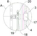
fig. 3 is a partially enlarged view of the area a in fig. 1 according to the present invention.
In the figure: 1. a cabinet body; 2. an element cavity; 3. an adjustment chamber; 4. a screw rod; 5. an audible and visual alarm; 6. a mounting frame; 7. a flue gas temperature sensor; 8. a single chip microcomputer; 9. a dry powder high-pressure storage tank; 10. a fixed mount; 11. a delivery pipe; 12. a main valve; 13. a servo motor; 14. a heat conducting plate; 15. a heat dissipating fin; 16. a heat dissipation fan; 17. a slider; 18. a dry powder spray head; 19. a connecting pipe; 20. an electromagnetic valve.
Detailed Description
The technical solutions in the embodiments of the present invention will be described clearly and completely with reference to the accompanying drawings in the embodiments of the present invention, and it is obvious that the described embodiments are only some embodiments of the present invention, not all embodiments.
Referring to fig. 1-3, the present invention provides an embodiment: the utility model provides a cubical switchboard for high-tension apparatus, the intelligent cabinet temperature adjusting device comprises a cabinet body 1, the inside of the cabinet body 1 is provided with component chamber 2, one side in component chamber 2 is provided with adjusts chamber 3, adjust the inside rotation in chamber 3 and install lead screw 4, the externally mounted of lead screw 4 has sliding block 17, and one side of sliding block 17 extends to the inside in component chamber 2, one side fixed mounting of sliding block 17 has dry powder shower nozzle 18, flue gas temperature sensor 7 is installed to one side of component chamber 2 upper end, and flue gas temperature sensor 7 passes through the screw fixation with the cabinet body 1, singlechip 8 is installed to the opposite side of component chamber 2 upper end, the inside of component chamber 2 is fixed and is provided with mounting bracket 6, the.
Further, one side of the cabinet body 1 is provided with dry powder high pressure storage tank 9, and dry powder high pressure storage tank 9 passes through mount 10 with the cabinet body 1 and fixes, the upper end of dry powder high pressure storage tank 9 is provided with conveyer pipe 11, conveyer pipe 11 is close to the one end of dry powder high pressure storage tank 9 and installs main valve 12, the upper end of dry powder shower nozzle 18 is provided with connecting pipe 19, and the one end and the conveyer pipe 11 of connecting pipe 19 are fixed sealedly, the one end fixed mounting that connecting pipe 19 is close to dry powder shower nozzle 18 has solenoid valve 20, and solenoid valve 20's input and singlechip 8's output electric connection, after opening solenoid valve 20, the inside dry powder of dry powder high pressure storage tank 9 passes through conveyer pipe 11 and gets into to connecting pipe 19, and spray dry powder to component chamber 2 inside through dry powder shower nozzle 18, thereby realize putting out a fire to rescue in the very first time.
Further, adjust the below in chamber 3 and install servo motor 13, and servo motor 13's output shaft passes through the shaft coupling transmission with the lower extreme in adjusting chamber 3 and is connected, sliding block 17 and lead screw 4 looks adaptation, and dry powder shower nozzle 18 can carry out vertical migration in the side of mounting bracket 6, sprays each region evenly to realize putting out a fire fast.
Further, audible and visual alarm 5 is installed to the top of the cabinet body 1 one side, and audible and visual alarm 5 passes through the screw fixation with the cabinet body 1, audible and visual alarm 5's input and singlechip 8's output electric connection, audible and visual alarm 5 can inform the site work personnel to react fast and handle.
Further, the rear end of heat-conducting plate 14 is provided with radiating fin 15, and radiating fin 15 is provided with a plurality of, and radiating fin 15 distributes in proper order, and radiating fin 15 and heat-conducting plate 14 structure as an organic whole, and inside heat can be absorbed by heat-conducting plate 14, and radiating fin 15 can derive the heat of the cabinet body 1 to realize the heat dissipation.
Further, the heat dissipation fans 16 are installed at four corners of the rear end of the heat conduction plate 14, the heat dissipation fans 16 are fixed with the heat conduction plate 14 through bolts, and the heat dissipation fans 16 can accelerate circulation of heat gas, so that the heat dissipation effect is further improved.
The working principle is as follows: when the fire extinguishing device is used, the temperature sensor 7 can identify the temperature and the smoke inside the cabinet body 1, when fire occurs inside due to power failure, the smoke temperature sensor 7 can quickly sense and send signals to the single chip microcomputer 8, the single chip microcomputer 8 simultaneously starts the audible and visual alarm 5 and the electromagnetic valve 20, the audible and visual alarm 5 can inform field workers to quickly perform reaction treatment, after the electromagnetic valve 20 is started, dry powder inside the dry powder high-pressure storage tank 9 enters the connecting pipe 19 through the conveying pipe 11 and sprays the dry powder inside the element cavity 2 through the dry powder spray head 18, so that fire extinguishing is realized at the first time, meanwhile, the single chip microcomputer 8 starts the servo motor 13, the output shaft of the servo motor 13 drives the screw rod 4 to rotate, under the matching of the screw rod 4 and the sliding block 17, the rotary motion is converted into the linear motion, and the sliding block 17 provided with the dry powder spray head 18 is enabled to vertically reciprocate on the screw rod 4, then the dry powder spray head 18 can move vertically on the side of the mounting frame 6 during the fire extinguishing process, and spray all areas uniformly to realize quick fire extinguishing.
It is obvious to a person skilled in the art that the invention is not restricted to details of the above-described exemplary embodiments, but that it can be implemented in other specific forms without departing from the spirit or essential characteristics of the invention. The present embodiments are therefore to be considered in all respects as illustrative and not restrictive, the scope of the invention being indicated by the appended claims rather than by the foregoing description, and all changes which come within the meaning and range of equivalency of the claims are therefore intended to be embraced therein. Any reference sign in a claim should not be construed as limiting the claim concerned.
Claims (6)
1. The utility model provides a cubical switchboard for high-tension apparatus, includes cabinet body (1), its characterized in that: the inside of the cabinet body (1) is provided with component chamber (2), one side of component chamber (2) is provided with adjusts chamber (3), the inside of adjusting chamber (3) is rotated and is installed lead screw (4), the externally mounted of lead screw (4) has sliding block (17), and one side of sliding block (17) extends to the inside of component chamber (2), one side fixed mounting of sliding block (17) has dry powder shower nozzle (18), flue gas temperature sensor (7) are installed to one side of component chamber (2) upper end, and flue gas temperature sensor (7) pass through the screw fixation with the cabinet body (1), singlechip (8) are installed to the opposite side of component chamber (2) upper end, the inside of component chamber (2) is fixed and is provided with mounting bracket (6), the rear end of mounting bracket (6) is provided with heat-conducting plate (14).
2. The switchgear for high voltage equipment according to claim 1, wherein: one side of the cabinet body (1) is provided with dry powder high-pressure storage tank (9), and dry powder high-pressure storage tank (9) is fixed through mount (10) with the cabinet body (1), the upper end of dry powder high-pressure storage tank (9) is provided with conveyer pipe (11), main valve (12) are installed to the one end that conveyer pipe (11) are close to dry powder high-pressure storage tank (9), the upper end of dry powder shower nozzle (18) is provided with connecting pipe (19), and the one end of connecting pipe (19) is sealed fixed with conveyer pipe (11), the one end fixed mounting that connecting pipe (19) are close to dry powder shower nozzle (18) has solenoid valve (20), and the input of solenoid valve (20) and the output electric connection of singlechip (8).
3. The switchgear for high voltage equipment according to claim 1, wherein: the servo motor (13) is installed below the adjusting cavity (3), the output shaft of the servo motor (13) is in transmission connection with the lower end of the adjusting cavity (3) through a coupler, and the sliding block (17) is matched with the screw rod (4).
4. The switchgear for high voltage equipment according to claim 1, wherein: audible-visual annunciator (5) are installed to the top of the cabinet body (1) one side, and audible-visual annunciator (5) pass through the screw fixation with the cabinet body (1), the input of audible-visual annunciator (5) and the output electric connection of singlechip (8).
5. The switchgear for high voltage equipment according to claim 1, wherein: the rear end of heat-conducting plate (14) is provided with radiating fin (15), and radiating fin (15) are provided with a plurality of, and radiating fin (15) distribute in proper order, radiating fin (15) and heat-conducting plate (14) structure as an organic whole.
6. The switchgear for high voltage equipment according to claim 5, wherein: the four corners of the rear end of the heat conducting plate (14) are provided with heat radiating fans (16), and the heat radiating fans (16) are fixed with the heat conducting plate (14) through bolts.
Priority Applications (1)
| Application Number | Priority Date | Filing Date | Title |
|---|---|---|---|
| CN202022989321.2U CN214153514U (en) | 2020-12-11 | 2020-12-11 | Switch cabinet for high-voltage equipment |
Applications Claiming Priority (1)
| Application Number | Priority Date | Filing Date | Title |
|---|---|---|---|
| CN202022989321.2U CN214153514U (en) | 2020-12-11 | 2020-12-11 | Switch cabinet for high-voltage equipment |
Publications (1)
| Publication Number | Publication Date |
|---|---|
| CN214153514U true CN214153514U (en) | 2021-09-07 |
Family
ID=77586193
Family Applications (1)
| Application Number | Title | Priority Date | Filing Date |
|---|---|---|---|
| CN202022989321.2U Active CN214153514U (en) | 2020-12-11 | 2020-12-11 | Switch cabinet for high-voltage equipment |
Country Status (1)
| Country | Link |
|---|---|
| CN (1) | CN214153514U (en) |
Cited By (1)
| Publication number | Priority date | Publication date | Assignee | Title |
|---|---|---|---|---|
| CN114976900A (en) * | 2022-05-18 | 2022-08-30 | 国网江苏省电力有限公司无锡供电分公司 | A kind of ring network cabinet based on NB-IOT technology that can self-extinguish fire and prevent electricity stealing |
-
2020
- 2020-12-11 CN CN202022989321.2U patent/CN214153514U/en active Active
Cited By (1)
| Publication number | Priority date | Publication date | Assignee | Title |
|---|---|---|---|---|
| CN114976900A (en) * | 2022-05-18 | 2022-08-30 | 国网江苏省电力有限公司无锡供电分公司 | A kind of ring network cabinet based on NB-IOT technology that can self-extinguish fire and prevent electricity stealing |
Similar Documents
| Publication | Publication Date | Title |
|---|---|---|
| CN213852849U (en) | Electric automatization switch board | |
| CN108092154A (en) | A kind of kitchen integrates power supply module and its construction technology | |
| CN214379325U (en) | High stable fire prevention type safety switch cabinet | |
| CN110012630A (en) | A kind of automation electrical control cabinet with function of safety protection | |
| CN217938952U (en) | Integrated fire-fighting inspection control cabinet | |
| CN214850079U (en) | A kind of insulated fully enclosed AC metal ring network switchgear | |
| CN219180998U (en) | Lightning protection and explosion prevention device of high-voltage switch cabinet | |
| CN102496877B (en) | Pressure relief apparatus of high voltage switch cabinet | |
| CN218770722U (en) | High tension switchgear with pressure release protection architecture | |
| CN218351994U (en) | High-voltage power distribution cabinet with fuse | |
| CN215911734U (en) | Intelligent control cabinet with fire detection alarm | |
| CN211956156U (en) | Distribution transformer monitoring devices | |
| CN216529998U (en) | Electrical control cabinet with automatic fire extinguishing function | |
| CN212162499U (en) | Block terminal for electrical engineering | |
| CN212849335U (en) | Box-type transformer with linkage type infrared detection fire extinguishing device | |
| CN218448979U (en) | High-voltage fireproof power distribution cabinet | |
| CN210278034U (en) | Nitrogen fire extinguishing device based on electrical cabinet | |
| CN220585740U (en) | Power distribution cabinet with fire extinguishing function | |
| CN219513534U (en) | High-voltage power distribution cabinet | |
| CN219811776U (en) | Power control box with high stability | |
| CN221947709U (en) | A switch cabinet | |
| CN217642316U (en) | Ring main unit with early warning function | |
| CN216529975U (en) | But explosion-proof switch board of high pressure of remote monitoring | |
| CN224110389U (en) | Energy storage battery container | |
| CN221283658U (en) | Control box that security is high |
Legal Events
| Date | Code | Title | Description |
|---|---|---|---|
| GR01 | Patent grant | ||
| GR01 | Patent grant |