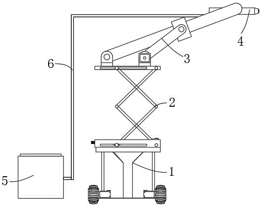
Movable lifting swing arm putty spraying robot
Technical Field
The utility model relates to a putty spraying robot technical field specifically is a portable lift swing arm putty spraying robot.
Background
The putty spraying machine is a small machine for stirring, pumping and spraying high-quality putty powder, is one of the putty spraying machines, and is mainly used for spraying various decorative putty produced at home and abroad, wherein, for example, the particles can achieve the atomization effect through a gas mixing spray gun for 100-mesh paint. The spraying area can reach about 1500 square meters every day, and the coating is suitable for house protection, painting, primer sizing and the like.
At present, a putty spraying machine with higher efficiency exists in the market, although the machine has more perfect functions in all aspects, the machine needs to be manually sprayed, and the putty spraying of a common manual handheld machine is not uniform in spraying of a robot, so that the loss of materials is increased, and the loss is reduced in order to save manpower. Therefore, it is necessary to design a movable type lifting swing arm putty spraying robot.
SUMMERY OF THE UTILITY MODEL
To the above situation, for overcoming prior art's defect, the utility model provides a portable lift swing arm putty spraying robot, this putty spraying robot, novel structure thinks about ingeniously, through the vertical face of vertical lift combination interior circumference swing in order to increase the coverage of spray gun, realizes the large tracts of land spraying to the wall body, promotes the work efficiency of spraying.
In order to achieve the above object, the utility model provides a following technical scheme: the utility model provides a portable lift swing arm putty spraying robot, includes and removes the base, the top of removing the base is installed and is cut the formula elevating platform, it installs swing guide arm mechanism to cut the top of formula elevating platform, the spray gun is installed on swing guide arm mechanism's top, the tail end of spray gun passes through the feed hose and is connected with the discharge gate of putty workbin.
Preferably, the movable base comprises a lower base plate, a support frame, first stepping motors, Mecanum wheels and an upper base plate, the upper base plate is fixed on the periphery of the top of the lower base plate through the support frame, the first stepping motors are installed at four corners of the top of the lower base plate, and the Mecanum wheels are installed at the output ends of the first stepping motors.
Preferably, the support frame comprises an N-shaped support frame and a T-shaped support frame, and the N-shaped support frame and the T-shaped support frame are distributed in a staggered mode.
Preferably, the scissor type lifting platform comprises a lifting platform base, a second stepping motor, a screw rod, a lower sliding rod, an internal thread sliding block, a lower sliding groove, a driving arm, a driven driving arm, a supporting platform, an upper sliding groove and an upper sliding rod, a second stepping motor is arranged at the center of the inner wall at one side of the lifting platform base, a screw rod is arranged at the output end of the second stepping motor, the screw rod is engaged with an internal thread sliding block, a lower sliding rod is arranged on the internal thread sliding block, two ends of the lower sliding rod are connected inside the lower sliding grooves on two sides of the lifting platform base in a sliding manner, two ends of the lower sliding rod are fixed with driving arms, a driven driving arm in driving connection with the driving arm is installed on one side of the top of the lifting platform base, the top end of the driven driving arm is fixed on one side of the bottom of the supporting platform, the top of initiative drive arm is fixed at the both ends of last slide bar, the both ends sliding connection of going up the slide bar is inside the last spout of supporting platform both sides.
Preferably, the swing guide rod mechanism comprises a hinge base, a swing rod, a sliding block, a motor base, a third step motor and a crank, the hinge base is fixed on one side of the top of the supporting platform, the swing rod is connected to the hinge base in a rotating mode, the sliding block is connected to the swing rod in a sliding mode, the crank is movably connected to the sliding block, the tail end of the crank is connected with the third step motor fixed to the motor base, the motor base is fixed to the supporting platform, and a spray gun is fixed to the top end of the swing rod.
The utility model has the advantages that:
can drive mecanum wheel through the first step motor that sets up and rotate, the convenience is removed putty spraying robot, degree of automation is high, make second step motor work simultaneously, it is rotatory to drive the lead screw, thereby make the internal thread slider move on the lead screw, then drive the lower slide bar motion, and then the drive initiative arm of driving, drive the motion of driven arm of driving, support platform's up-and-down motion has finally been realized, and cooperate third step motor work, it is circular motion to drive the crank, thereby make the slider move on the pendulum rod, finally drive the pendulum rod and do the swing motion under the circumference, through the vertical lift joint vertical in the circumference swing in order to increase the coverage of spray gun, realize the large tracts of land spraying to the wall body, the work efficiency of promotion spraying.
Drawings
The accompanying drawings are included to provide a further understanding of the invention, and are incorporated in and constitute a part of this specification, illustrate embodiments of the invention, and together with the description serve to explain the invention and not to limit the invention. In the drawings:
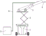
FIG. 1 is a schematic view of the overall plane structure of the present invention;
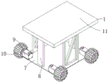
fig. 2 is a schematic diagram of a three-dimensional structure of the mobile base of the present invention;
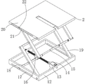
FIG. 3 is a schematic view of a three-dimensional structure of the scissor lift of the present invention;
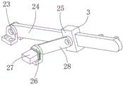
fig. 4 is a schematic diagram of the three-dimensional structure of the swing guide bar mechanism of the present invention;
reference numbers in the figures: 1. moving the base; 2. a scissor lift table; 3. a swing guide bar mechanism; 4. a spray gun; 5. a putty box; 6. a supply hose; 7. a lower base plate; 8. a support frame; 9. a first stepper motor; 10. a Mecanum wheel; 11. an upper base plate; 12. a lifting platform base; 13. a second stepping motor; 14. a screw rod; 15. a lower sliding rod; 16. an internal thread slider; 17. a lower chute; 18. an active drive arm; 19. a driven drive arm; 20. a support platform; 21. an upper chute; 22. a sliding rod is arranged; 23. a hinge mount; 24. a hinge mount; 25. a slider; 26. a motor base; 27. a stepping motor; 28. a crank.
Detailed Description
The technical solutions in the embodiments of the present invention will be described clearly and completely with reference to the accompanying drawings in the embodiments of the present invention, and it is obvious that the described embodiments are only some embodiments of the present invention, not all embodiments. Based on the embodiments in the present invention, all other embodiments obtained by a person skilled in the art without creative work belong to the protection scope of the present invention.
Given by fig. 1-4, the utility model provides the following technical scheme: the utility model provides a portable lift swing arm putty spraying robot, includes and removes base 1, removes the top of base 1 and installs and cut formula elevating platform 2, cuts the top of formula elevating platform 2 and installs swing guide arm mechanism 3, and spray gun 4 is installed on the top of swing guide arm mechanism 3, and the tail end of spray gun 4 is connected with the discharge gate of putty workbin 5 through feed hose 6.
The movable base 1 comprises a lower base plate 7, a support frame 8, a first stepping motor 9, Mecanum wheels 10 and an upper base plate 11, the upper base plate 11 is fixed on the periphery of the top of the lower base plate 7 through the support frame 8, the first stepping motor 9 is installed at four corner positions of the top of the lower base plate 7, and the Mecanum wheels 10 are installed at the output end of the first stepping motor 9.
The support frame 8 comprises an N-shaped support frame and a T-shaped support frame, and the N-shaped support frame and the T-shaped support frame are distributed in a staggered mode.
The scissor type lifting platform 2 comprises a lifting platform base 12, a second stepping motor 13, a screw rod 14, a lower sliding rod 15, an internal thread slider 16, a lower sliding groove 17, a driving arm 18, a driven driving arm 19, a supporting platform 20, an upper sliding groove 21 and an upper sliding rod 22, wherein the second stepping motor 13 is arranged at the center of the inner wall of one side of the lifting platform base 12, the screw rod 14 is arranged at the output end of the second stepping motor 13, the internal thread slider 16 is meshed and connected on the screw rod 14, the lower sliding rod 15 is arranged on the internal thread slider 16, two ends of the lower sliding rod 15 are slidably connected inside the lower sliding groove 17 at two sides of the lifting platform base 12, the driving arm 18 is fixed at two ends of the lower sliding rod 15, a driven driving arm 19 in driving connection with the driving arm 18 is arranged at one side of the top of the lifting platform base 12, the top end of the driven driving arm 19 is fixed at one side of the bottom of the supporting platform 20, the top end of the driving arm 18 is fixed at two ends of the upper sliding rod 22, the two ends of the upper slide bar 22 are slidably connected to the inside of the upper slide grooves 21 at the two sides of the supporting platform 20.
The swing guide rod mechanism 3 comprises a hinge seat 23, a swing rod 24, a slide block 25, a motor seat 26, a third step motor 27 and a crank 28, the hinge seat 23 is fixed on one side of the top of the supporting platform 20, the swing rod 24 is connected to the hinge seat 23 in a rotating mode, the slide block 25 is connected to the swing rod 24 in a sliding mode, the crank 28 is movably connected to the slide block 25, the tail end of the crank 28 is connected with the third step motor 27 fixed to the motor seat 26, the motor seat 26 is fixed to the supporting platform 20, and the spray gun 4 is fixed to the top end of the swing rod 24.
The utility model discloses during the use, can drive mecanum wheel 10 through the first step motor 9 that sets up and rotate, the convenience removes putty spraying robot, degree of automation is high, make second step motor 13 work simultaneously, it is rotatory to drive lead screw 14, thereby make internal thread slider 16 move on lead screw 14, slide bar 15 motion down is driven then, and then the drive initiative drives arm 18, drive the motion of driven arm 19, the up-and-down motion of supporting platform 20 has finally been realized, and cooperate the work of third step motor 27, it is circular motion to drive crank 28, thereby make slider 25 move on pendulum rod 24, finally drive pendulum rod 24 and do the swing motion under the circumference, through the coverage of the interior circumference swing of vertical face in the vertical lift combination with the increase spray gun, realize the large tracts of land spraying to the wall body, promote the work efficiency of spraying.
Finally, it should be noted that: although the present invention has been described in detail with reference to the foregoing embodiments, it will be apparent to those skilled in the art that modifications may be made to the embodiments described in the foregoing embodiments, or equivalents may be substituted for elements thereof. Any modification, equivalent replacement, or improvement made within the spirit and principle of the present invention should be included in the protection scope of the present invention.