CN214117710U - Detachable parking shed - Google Patents
Detachable parking shed Download PDFInfo
- Publication number
- CN214117710U CN214117710U CN202022562854.2U CN202022562854U CN214117710U CN 214117710 U CN214117710 U CN 214117710U CN 202022562854 U CN202022562854 U CN 202022562854U CN 214117710 U CN214117710 U CN 214117710U
- Authority
- CN
- China
- Prior art keywords
- main frame
- tarpaulin
- frame
- connector
- parking shed
- Prior art date
- Legal status (The legal status is an assumption and is not a legal conclusion. Google has not performed a legal analysis and makes no representation as to the accuracy of the status listed.)
- Active
Links
- 230000003014 reinforcing effect Effects 0.000 claims abstract description 24
- 230000002787 reinforcement Effects 0.000 claims abstract description 8
- XEEYBQQBJWHFJM-UHFFFAOYSA-N Iron Chemical compound [Fe] XEEYBQQBJWHFJM-UHFFFAOYSA-N 0.000 claims description 4
- 239000003351 stiffener Substances 0.000 claims description 4
- 229910052742 iron Inorganic materials 0.000 claims description 2
- 238000006073 displacement reaction Methods 0.000 abstract description 2
- 239000004744 fabric Substances 0.000 description 5
- 238000009434 installation Methods 0.000 description 2
- 230000004075 alteration Effects 0.000 description 1
- 230000009286 beneficial effect Effects 0.000 description 1
- 230000000694 effects Effects 0.000 description 1
- 238000012986 modification Methods 0.000 description 1
- 230000004048 modification Effects 0.000 description 1
- 238000005728 strengthening Methods 0.000 description 1
- 238000006467 substitution reaction Methods 0.000 description 1
Images



Landscapes
- Tents Or Canopies (AREA)
Abstract
The utility model discloses a detachable parking shed, which comprises a main frame, a base, tarpaulin and a reinforcement; the main frame is a detachable frame structure consisting of a plurality of rod pieces, and is rectangular when viewed from top; the bottom of the main frame is provided with a plurality of bases, and the bases are fixedly arranged on the ground; the tarpaulin covers the top surface of the main frame. The utility model has the advantages that the utility model adopts a detachable symmetrical structure as a whole, has the advantages of strong wind resistance, strong maneuverability and stable structure, and is suitable for the daily use of a common vehicle owner; the utility model arranges the reinforcing rods on the frame units, arranges the reinforcing pieces between the frame units and the cross beams, and obviously improves the stability of the whole main frame; the utility model discloses encircle whole tarpaulin in the two crossbeam outsides that correspond to arrange, install the tarpaulin at main frame top surface on the one hand, on the other hand passes through the limiting displacement of tarpaulin, guarantees whole main frame structure's compact and stability.
Description
Technical Field
The utility model relates to a parking shed technical field especially relates to a detachable parking shed.
Background
The automobile is an indispensable vehicle in daily life of people. With the increasing of automobiles, parking also becomes a concern of many owners, and rain or insolation can cause certain damage to the automobiles, so that the automobiles need to be parked under a parking shed or in a parking lot, and the automobiles are prevented from being directly exposed to rain or sunlight.
At present, the existing portable parking shed mostly adopts a simple four-leg structure, and no reinforcing design is adopted between the structure domain structures, so that the wind resistance of the awning cloth is too large, the wind power of a pit of the whole parking shed is caused, the stability is not strong, and the phenomena of collapse and damage to a car body are easy to occur.
SUMMERY OF THE UTILITY MODEL
1. Technical problem to be solved
An object of the utility model is to provide a detachable parking shed avoids the not strong problem of current parking shed stability, when keeping parking shed mobility, ensures the wind resistance and the stability of whole parking shed structure.
2. Technical scheme
In order to achieve the above object, the utility model provides a following technical scheme: a detachable parking shed comprises a main frame, a base, tarpaulin and a reinforcement; the main frame is a detachable frame structure consisting of a plurality of rod pieces, and the main frame is a right-angled quadrangle in overlooking; the bottom of the main frame is provided with a plurality of bases, and the bases are fixedly arranged on the ground; the tarpaulin covers the top surface of the main frame and is detachably and fixedly arranged on the main frame; and the plurality of reinforcing pieces are detachably arranged at the corner positions of the upper part of the main frame.
In the above-mentioned detachable carport, the main frame includes frame units arranged at equal intervals, and two adjacent frame units are connected by a plurality of cross beams; each frame unit comprises a column, an oblique beam, a top connector and a side connector; the bottoms of the two columns are connected with the base, and the tops of the two columns are respectively connected with the bottom of the oblique beam through the side connectors; the tops of the two inclined beams are connected through the top connector.
In the above-mentioned detachable parking shed, the frame units have a symmetrical structure.
In the detachable parking shed, the plurality of cross beams are detachably and fixedly connected with the top connector and the side connectors so as to connect two adjacent frame units.
The detachable parking shed is characterized in that the number of the frame units is not less than one.
In the above-mentioned detachable parking shed, the top connectors and the side connectors of the frame units at both ends are three-way connectors; the middle top connector and the side connector of the frame unit are four-way connectors.
In the detachable parking shed, the tarpaulin is sewn with tarpaulin strips near the inner sides of the four peripheries; the awning cloth strip and the awning cloth are equally spaced and provided with a first air hole and a second air hole which are correspondingly arranged; the elastic rope passes through the first air hole and the second air hole. So as to wrap the tarpaulin strips and the tarpaulin on the cross beams or the oblique beams around the main frame.
In the above-mentioned detachable parking shed, the reinforcing member is a rod member, and both ends of the reinforcing member are respectively fixedly connected to the pillar and the cross beam.
The detachable parking shed further comprises a reinforcing rod and a reinforcing connector; two strengthen the connector symmetry and install two of frame element on the sloping, the stiffener both ends respectively with two strengthen the connector and be connected.
3. Advantageous effects
To sum up, the beneficial effects of the utility model reside in that:
(1) the detachable parking shed of the utility model adopts a detachable symmetrical structure as a whole, has the advantages of strong maneuverability and stable structure, and is suitable for the daily use of ordinary car owners;
(2) the detachable parking shed of the utility model arranges the reinforcing rods on the frame units, arranges the reinforcing pieces between the frame units and the cross beams, and obviously improves the stability of the whole main frame;
(3) the utility model discloses a detachable parking shed encircles whole tarpaulin in two crossbeams and the sloping outside that correspond to arrange, installs the tarpaulin at main frame top surface on the one hand, and on the other hand passes through the limiting displacement of tarpaulin, guarantees whole main frame structure's compactness and stability.
Drawings
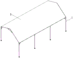
Fig. 1 is a schematic structural view of the detachable parking shed of the utility model;
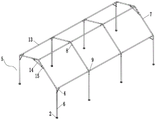
fig. 2 is a schematic structural view of the main frame of the detachable carport of the present invention;
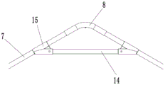
FIG. 3 is a schematic view of the detachable reinforcing member for the parking shed according to the present invention;
FIG. 4 is a schematic view of the detachable reinforcing rods and reinforcing connectors of the parking shed of the present invention;
FIG. 5 is a schematic view of the detachable awning cloth and pipe fitting of the present invention;
fig. 6 is the utility model discloses detachable parking shed tarpaulin and the installation cross-sectional view of pipe fitting.
In the figure, 1-main frame; 2-a base; 3-tarpaulin; 4-a reinforcement; 5-a frame unit; 6-column; 7-an oblique beam; 8-top connector; 9-side connector; 10-tarpaulin strips; 11-a first air hole; 12-second air hole; 13-a cross beam; 14-a reinforcing rod; 15-reinforcing the connector; 16-elastic cord.
Detailed Description
The technical solutions in the embodiments of the present invention will be described clearly and completely with reference to the accompanying drawings in the embodiments of the present invention, and it is obvious that the described embodiments are only some embodiments of the present invention, not all embodiments. Based on the embodiments in the present invention, all other embodiments obtained by a person skilled in the art without creative work belong to the protection scope of the present invention.
Referring to fig. 1 to 6, the present invention provides the following technical solutions: a detachable parking shed comprises a main frame 1, a base 2, tarpaulin 3 and a reinforcement 4; the main frame 1 is a detachable frame structure consisting of a plurality of rod pieces, and the main frame 1 is rectangular in a top view; the bottom of the main frame 1 is provided with a plurality of bases 2, and the bases 2 are fixedly arranged on the ground; the tarpaulin 3 covers the top surface of the main frame 1 and is detachably and fixedly arranged on the main frame 1; a plurality of the reinforcing members 4 are detachably installed at the corner positions of the upper part of the main frame 1. The main frame 1 is of a symmetrical structure and comprises frame units 5 which are arranged at equal intervals, and two adjacent frame units 5 are connected through a plurality of cross beams 13; each frame unit 5 comprises a column 6, an oblique beam 7, a top connector 8 and a side connector 9; the bottoms of the two columns 6 are connected with the base 2, and the tops of the two columns are respectively connected with the bottoms of the oblique beams 7 through the side connectors 9; the tops of the two oblique beams 7 are connected through the top connector 8.
Preferably, a plurality of the cross beams 13 are detachably and fixedly connected with the top connector 8 and the side connector 9 so as to connect two adjacent frame units 5.
The number of the frame units 5 is not less than 3. Preferably, the top connector 8 and the side connector 9 of the frame unit 5 at two ends are three-way connectors; the middle top connector 8 and the side connector 9 of the frame unit 5 are four-way connectors.
Preferably, tarpaulin strips 10 are sewn on the inner sides of the peripheries of the tarpaulin 3; the tarpaulin strip 10 and the tarpaulin 3 are equally spaced and provided with a first air hole 11 and a second air hole 12 which are correspondingly arranged; elastic ropes 16 penetrate through the first air holes 11 and the second air holes 12 so as to wrap the tarpaulin strips 10 and the tarpaulin 3 on the cross beams 13 or the oblique beams 7 around the main frame.
Preferably, the reinforcing member 4 is an iron bar, and both ends of the reinforcing member are fixedly connected to the column 6 and the cross beam 13, respectively, for improving the connection stability between the frame unit 5 and the cross beam 13, thereby ensuring the stability of the entire main frame 1.
Preferably, the device also comprises a reinforcing rod 14 and a reinforcing connecting head 15; two strengthen the connector 15 symmetry and install two of frame element 5 on the sloping 7, 14 both ends of stiffener are respectively with two strengthen the connector 15 and connect, be used for strengthening frame element 5's connection steadiness.
During the use, begin the equipment by the lower angle terminal surface on the left side, base 2 is connected with post 6, post 3 with side connector 9 is connected, side connector 9 with sloping 7 is connected, and sloping 7 passes strengthen connector 15 with it connects to push up connector 8, 14 both ends of stiffener and two strengthen the connector 15 and connect. Middle two frame cell 5 does not strengthen 14 and reinforcement connection head 15, just top connector 8 and side connector 9 are changed into the cross-connection head by the tee bend connector, adjacent two frame cell 5 passes through crossbeam 13 is connected to this analogizes, until accomplishing the installation of main frame 1, installs at last reinforcement 4 extremely 1 upper portion four corners relative position of main frame, this moment 14 both ends of reinforcement are connected with post 6 and crossbeam 13 respectively. The tarpaulin strip 10 is provided with a first air hole 11, and the side of the tarpaulin 3 corresponding to the first air hole 11 is provided with a second air hole 12. The elastic rope 16 passes through the first air hole 11, the second air hole 12 bypasses the cross beam 13 or the oblique beam 7 on the corresponding four sides of the main frame 1, the elastic rope 16 passes through the second air hole 12, and the awning cloth 3 is installed on the top of the main frame 1 through the elastic rope 16.
Although embodiments of the present invention have been shown and described, it will be appreciated by those skilled in the art that changes, modifications, substitutions and alterations can be made in these embodiments without departing from the principles and spirit of the invention, the scope of which is defined in the appended claims and their equivalents.
Claims (9)
1. The utility model provides a detachable parking shed which characterized in that: comprises a main frame (1), a base (2), tarpaulin (3) and a reinforcement (4); the main frame (1) is a detachable frame structure consisting of a plurality of rod pieces, and the main frame (1) is a right-angled quadrangle in overlooking; the bases (2) are installed at the bottom of the main frame (1), and the bases (2) are fixedly installed on the ground; the tarpaulin (3) covers the top surface of the main frame (1) and is detachably and fixedly arranged on the main frame (1); the reinforcing pieces (4) are detachably arranged at the corner positions of the upper part of the main frame (1).
2. A demountable parking shed as defined in claim 1, wherein: the main frame (1) comprises frame units (5) which are arranged at equal intervals, and two adjacent frame units (5) are connected through a plurality of cross beams (13); each frame unit (5) comprises a column (6), an oblique beam (7), a top connector (8) and a side connector (9); the bottoms of the two columns (6) are connected with the base (2), and the tops of the two columns are respectively connected with the bottom of the oblique beam (7) through the side connectors (9); the tops of the two oblique beams (7) are connected through the top connector (8).
3. A demountable parking shed as defined in claim 2, wherein: the frame unit (5) is of a symmetrical structure.
4. A demountable parking shed as defined in claim 2, wherein: a plurality of crossbeam (13) with fixed connection can be dismantled with side connector (9) to top connector (8) with connect adjacent two frame element (5).
5. A demountable parking shed as defined in claim 2, wherein: the number of the frame units (5) is not less than 2.
6. A demountable parking shed as defined in claim 5, wherein: the top connector (8) and the side connector (9) of the frame unit (5) at two ends are three-way connectors; the middle of the frame unit (5) is provided with a top connector (8) and a side connector (9) which are four-way connectors.
7. A demountable parking shed as defined in claim 2, wherein: tarpaulin strips (10) are sewn on the inner sides of the peripheries of the tarpaulin (3); the tarpaulin strip (10) and the tarpaulin (3) are provided with a first air hole (11) and a second air hole (12) which are correspondingly arranged at equal intervals; the elastic rope (16) penetrates through the first air hole (11) and the second air hole (12) to wrap the tarpaulin strip (10) and the tarpaulin (3) on the cross beam (13) or the oblique beam (7) on the periphery of the main frame (1).
8. A demountable parking shed as defined in claim 2, wherein: the reinforcing piece (4) is an iron bar, and two ends of the reinforcing piece are respectively fixedly connected with the column (6) and the cross beam (13).
9. A demountable parking shed as defined in claim 6, wherein: the device also comprises a reinforcing rod (14) and a reinforcing connector (15); two strengthen connector (15) symmetry and install two of frame element (5) on sloping (7), stiffener (14) both ends respectively with two strengthen the connector (15) and be connected.
Priority Applications (1)
| Application Number | Priority Date | Filing Date | Title |
|---|---|---|---|
| CN202022562854.2U CN214117710U (en) | 2020-11-09 | 2020-11-09 | Detachable parking shed |
Applications Claiming Priority (1)
| Application Number | Priority Date | Filing Date | Title |
|---|---|---|---|
| CN202022562854.2U CN214117710U (en) | 2020-11-09 | 2020-11-09 | Detachable parking shed |
Publications (1)
| Publication Number | Publication Date |
|---|---|
| CN214117710U true CN214117710U (en) | 2021-09-03 |
Family
ID=77502940
Family Applications (1)
| Application Number | Title | Priority Date | Filing Date |
|---|---|---|---|
| CN202022562854.2U Active CN214117710U (en) | 2020-11-09 | 2020-11-09 | Detachable parking shed |
Country Status (1)
| Country | Link |
|---|---|
| CN (1) | CN214117710U (en) |
-
2020
- 2020-11-09 CN CN202022562854.2U patent/CN214117710U/en active Active
Similar Documents
| Publication | Publication Date | Title |
|---|---|---|
| US5573026A (en) | Boat lift canopy | |
| US20090293927A1 (en) | Shelter having an extendable roof | |
| CN217257138U (en) | A foldable maintenance canopy for prefabricated component maintenance | |
| CN213898380U (en) | Soft-top awning with water accumulation prevention device | |
| CN220130277U (en) | Marine weather shed | |
| CN214942887U (en) | Photovoltaic parking shed | |
| CN111535624A (en) | Automatic folding type movable metal stand with turning plate type seat and awning | |
| CN111395822A (en) | Wind and rain shed | |
| CN216277163U (en) | Electric bicycle charging shed | |
| CN204826861U (en) | Foldable oblique top surface tent | |
| CN214994960U (en) | Multifunctional Aluminum Ground Beam Glass Wall Mounting Structure | |
| CN212984199U (en) | Telescopic module assembling movable house | |
| CN220434403U (en) | Canopy | |
| CN215978748U (en) | Outdoor tent capable of being connected with automobile trunk | |
| CN220414800U (en) | Auxiliary pile is last to set up installation work platform | |
| CN222456980U (en) | Photovoltaic bicycle shed | |
| CN219322037U (en) | High-span power bridge | |
| CN220255254U (en) | Crop planting protection system | |
| CN214473708U (en) | A joint for the canopy of the ultraviolet discharge detection device | |
| CN219509394U (en) | Protective fence convenient for butt joint installation | |
| CN223202827U (en) | Saddle type frame structure tent | |
| CN218740557U (en) | Self-service carwash is with straining horizontal stand | |
| CN223661504U (en) | Outdoor quick detach consolidates tent | |
| CN222542116U (en) | A steel structure assembled parking shed | |
| CN222701643U (en) | Portable single outdoor tent |
Legal Events
| Date | Code | Title | Description |
|---|---|---|---|
| GR01 | Patent grant | ||
| GR01 | Patent grant |