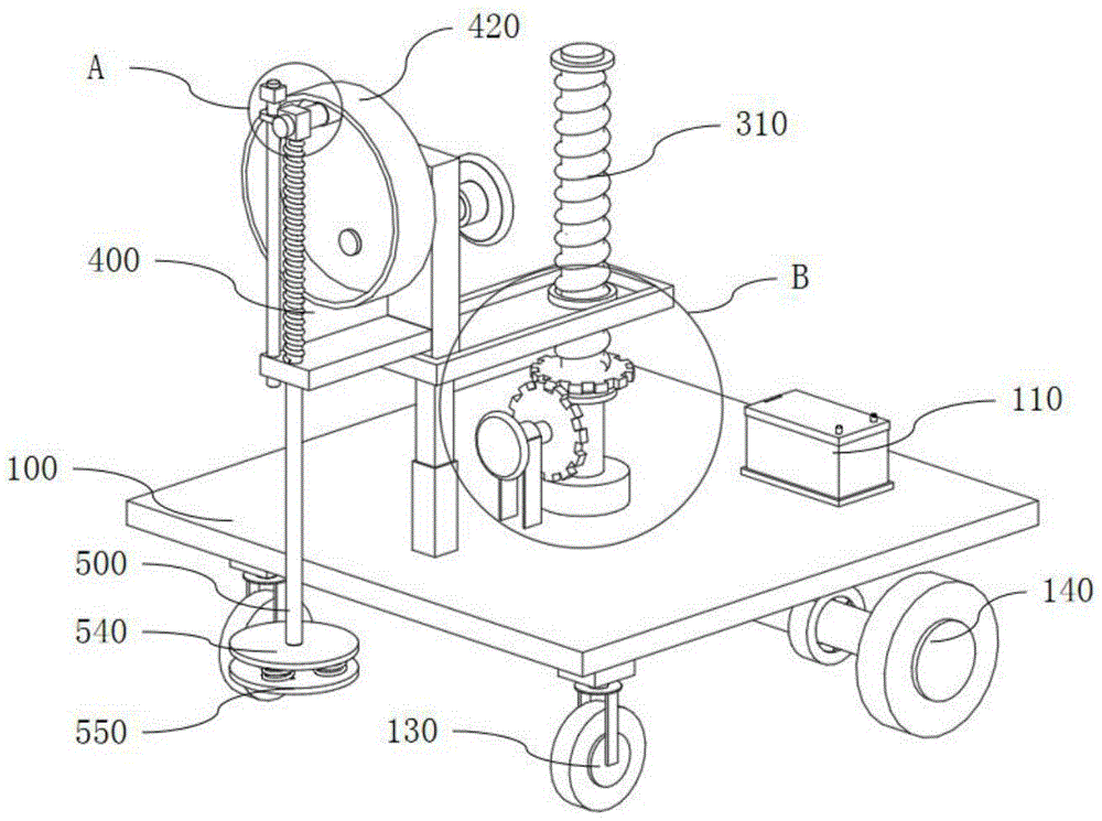
Installation hammer convenient for floor installation
Technical Field
The utility model relates to a mechanical tool technical field, in particular to make things convenient for installation hammer of floor installation.
Background
The floor, i.e. the surface layer of the floor or floor of a house, is made of wood or other materials, and the wooden floor essentially needs a hammer during the installation process.
The existing hammer is generally an iron hammer, a wooden floor is easily damaged during installation, manual hammering force is different during installation, and installation of the wood floor is inconvenient.
SUMMERY OF THE UTILITY MODEL
The utility model aims to provide a make things convenient for installation hammer of floor installation can effectively solve the problem of damaging timber apron and inconvenient installation easily among the background art.
In order to achieve the above purpose, the utility model adopts the following technical scheme: the utility model provides an installation hammer convenient to floor installation, includes base, loading board, elevating gear, reciprocating device and beats the device, the base includes base body and drive arrangement, drive arrangement installs in the base body lower surface, the loading board includes loading board body and screw ring, screw ring surface and loading board body internal surface connection, elevating gear includes threaded rod and fixed plate, screw ring and the rotatory cooperation of threaded rod, fixed plate lower surface and base body upper surface connection, the threaded rod is equipped with the roating seat, roating seat lower surface and base body upper surface connection, reciprocating device includes support column, backup pad and follows the driving wheel, support column lower surface and loading board body upper surface connection, backup pad one side surface and support column one side surface connection, it includes fixed block, hammer the device of beating, The inner surface of the fixed block is connected with the outer surface of the driven wheel, the upper surface of the supporting plate is provided with a round hole, the push rod is in sliding fit with the round hole, and two ends of the reset spring are respectively connected with the upper surface of the supporting plate and the lower surface of the fixed block.
Preferably, the base still includes battery, bracing piece and universal wheel, battery lower surface and base body upper surface connection, two the bracing piece upper surface all with base body lower surface connection, two the universal wheel upper surface respectively with two bracing piece lower surface connections, wherein, bracing piece and universal wheel have four, the setting up of universal wheel makes the device be convenient for remove.
Preferably, the bearing plate further comprises a telescopic rod, one end of the telescopic rod is welded to the lower surface of the bearing plate body, the other end of the telescopic rod is welded to the upper surface of the base body, and the bearing plate is used for bearing the reciprocating device and the hammering device.
Preferably, elevating gear still includes first motor, first gear and second gear, fixed plate upper surface and first motor surface are connected, first motor is equipped with the rotation axis, first gear and rotation axis normal running fit, second gear and first gear engagement, second gear and threaded rod normal running fit, elevating gear's effect is the distance of being convenient for adjust the device of beating off the ground, the control dynamics of beating.
Preferably, reciprocating device still includes second motor, cam, stopper and slide bar, the second motor is equipped with the axis of rotation, cam and axis of rotation normal running fit, slide bar one end and backup pad upper surface connection, stopper internal surface and slide bar surface connection, the fixed block passes through the slider with the slide bar and is connected, and reciprocating device's effect is that the drive is beaten the device and is reciprocating motion, makes the dynamics of beating at every turn unanimous.
Preferably, the hammering device further comprises a first hammering plate, a second hammering plate and buffer springs, the upper surface of the first hammering plate is connected with the other end of the push rod, the first hammering plate and the second hammering plate are connected through the buffer springs, the second hammering plate is a rubber plate, and protection of the wood floor is facilitated.
Compared with the prior art, the utility model discloses following beneficial effect has:
the utility model discloses in, remove wooden bottom plate upper surface with the device, drive arrangement enables the device autonomous movement, adjusts the carrier plate position through elevating gear, makes second hammer the board apart from a certain position on ground, and the second motor drives the cam rotation, makes to beat the device and can prolong the slide bar and be reciprocating motion, and second hammer the board and be the rubber slab, makes through buffer spring and beats the device dynamics when hammering the floor even, and not fragile timber apron.
Drawings
Fig. 1 is an isometric view of a mounting hammer of the present invention for facilitating floor installation;
FIG. 2 is a side view of a mounting hammer of the present invention for facilitating floor installation;
FIG. 3 is an enlarged view of the point A of FIG. 1 according to the present invention;
fig. 4 is an enlarged view of the point B in fig. 1 according to the present invention.
In the figure: 100. a base; 110. a storage battery; 120. a support bar; 130. a universal wheel; 140. a drive device; 200. a carrier plate; 210. a telescopic rod; 220. a threaded ring; 300. a lifting device; 310. a threaded rod; 320. a first motor; 330. a first gear; 340. a second gear; 350. a fixing plate; 400. A reciprocating device; 410. a second motor; 420. a cam; 430. a support pillar; 440. a support plate; 450. A limiting block; 460. a slide bar; 470. a driven wheel; 500. a hammering device; 510. a fixed block; 520. A push rod; 530. a return spring; 540. a first hammering plate; 550. a second hammering plate; 560. a buffer spring.
Detailed Description
In order to make the technical means, creation features, achievement purposes and functions of the present invention easy to understand, the present invention is further described below with reference to the following embodiments.
In the description of the present invention, it should be noted that the terms "upper", "lower", "inner", "outer", "front end", "rear end", "both ends", "one end", "the other end" and the like indicate orientations or positional relationships based on the orientations or positional relationships shown in the drawings, and are only for convenience of description and simplification of description, but do not indicate or imply that the device or element to which the reference is made must have a specific orientation, be constructed in a specific orientation, and be operated, and thus, should not be construed as limiting the present invention. Furthermore, the terms "first" and "second" are used for descriptive purposes only and are not to be construed as indicating or implying relative importance.
In the description of the present invention, it is to be noted that, unless otherwise explicitly specified or limited, the terms "mounted," "disposed," "connected," and the like are to be construed broadly, and for example, "connected" may be either fixedly connected or detachably connected, or integrally connected; can be mechanically or electrically connected; they may be connected directly or indirectly through intervening media, or they may be interconnected between two elements. The specific meaning of the above terms in the present invention can be understood in specific cases to those skilled in the art.
Referring to fig. 1-4, the present invention relates to an installation hammer for facilitating floor installation, which comprises a base 100, a loading plate 200, a lifting device 300, a reciprocating device 400 and a hammering device 500, wherein the base 100 comprises a base body and a driving device 140, the driving device 140 is installed on the lower surface of the base body, the loading plate 200 comprises a loading plate body and a threaded ring 220, the outer surface of the threaded ring 220 is connected with the inner surface of the loading plate body, the lifting device 300 comprises a threaded rod 310 and a fixing plate 350, the threaded ring 220 is rotatably engaged with the threaded rod 310, the lower surface of the fixing plate 350 is connected with the upper surface of the base body, the threaded rod 310 is provided with a rotary seat, the lower surface of the rotary seat is connected with the upper surface of the base body, the reciprocating device 400 comprises a support column 430, a support plate 440 and a driven wheel 470, the lower surface of the support column 430 is connected with the upper surface of the loading plate body, one side surface of the support plate 440 is connected with one side surface of the support column 430, the hammering device 500 includes a fixing block 510, a push rod 520, and a return spring 530, wherein an inner surface of the fixing block 510 is connected to an outer surface of the driven wheel 470, an upper surface of the supporting plate 440 is provided with a circular hole, the push rod 520 is slidably engaged with the circular hole, and both ends of the return spring 530 are respectively connected to an upper surface of the supporting plate 440 and a lower surface of the fixing block 510.
Further, the base 100 further comprises a storage battery 110, support rods 120 and universal wheels 130, the lower surface of the storage battery 110 is connected with the upper surface of the base body, the upper surfaces of the two support rods 120 are connected with the lower surface of the base body, the upper surfaces of the two universal wheels 130 are respectively connected with the lower surfaces of the two support rods 120, the number of the support rods 120 and the number of the universal wheels 130 are four, and the arrangement of the universal wheels 130 enables the device to be convenient to move.
Further, the supporting plate 200 further comprises a telescopic rod 210, one end of the telescopic rod 210 is welded to the lower surface of the supporting plate body, the other end of the telescopic rod 210 is welded to the upper surface of the base body, and the supporting plate 200 is used for supporting the reciprocating device 400 and the hammering device 500.
Further, the lifting device 300 further comprises a first motor 320, a first gear 330 and a second gear 340, the upper surface of the fixing plate 350 is connected with the outer surface of the first motor 320, the first motor 320 is provided with a rotating shaft, the first gear 330 is in rotating fit with the rotating shaft, the second gear 340 is meshed with the first gear 330, the second gear 340 is in rotating fit with the threaded rod 310, and the lifting device 300 is used for conveniently adjusting the distance between the hammering device 500 and the ground and controlling the hammering force.
Further, the reciprocating device 400 further comprises a second motor 410, a cam 420, a limiting block 450 and a sliding rod 460, the second motor 410 is provided with a rotating shaft, the cam 420 is in rotating fit with the rotating shaft, one end of the sliding rod 460 is connected with the upper surface of the supporting plate 440, the inner surface of the limiting block 450 is connected with the outer surface of the sliding rod 460, the fixing block 510 is connected with the sliding rod 460 through a sliding block, and the reciprocating device 400 is used for driving the hammering device 500 to do reciprocating motion so that the hammering force is consistent.
Further, the hammering device 500 further comprises a first hammering plate 540, a second hammering plate 550 and a buffer spring 560, the upper surface of the first hammering plate 540 is connected with the other end of the push rod 520, the first hammering plate 540 and the second hammering plate 550 are connected through a plurality of buffer springs 560, and the second hammering plate 550 is a rubber plate, which is beneficial to protecting wood floors from being damaged.
The working principle of the utility model is as follows:
referring to fig. 1-4, the present invention relates to an installation hammer for facilitating floor installation, wherein the type of the first motor 320 is YE2-132S1-2, the type of the second motor 410 is YE2-132S1-2, the device is moved to the upper surface of a wooden bottom plate, the driving device 140 enables the device to move autonomously, the position of the bearing plate 200 is adjusted by the lifting device 300, the second hammering plate 550 is spaced from the ground by a certain distance, the second motor 410 drives the cam 420 to rotate, the hammering device 500 can extend the sliding rod 460 to reciprocate, the second hammering plate 550 is a rubber plate, the hammering device 500 has uniform force when hammering the floor through the buffer spring 560, and the floor is not easily damaged.
The basic principles and the main features of the invention and the advantages of the invention have been shown and described above. It will be understood by those skilled in the art that the present invention is not limited to the above embodiments, and that the foregoing embodiments and descriptions are provided only to illustrate the principles of the present invention without departing from the spirit and scope of the present invention. The scope of the invention is defined by the appended claims and equivalents thereof.