CN214114452U - Multistation blowing machine for spring washer - Google Patents

Multistation blowing machine for spring washer Download PDF

Info

Publication number
CN214114452U
CN214114452U CN202120012766.7U CN202120012766U CN214114452U CN 214114452 U CN214114452 U CN 214114452U CN 202120012766 U CN202120012766 U CN 202120012766U CN 214114452 U CN214114452 U CN 214114452U
Authority
CN
China
Prior art keywords
ball
support column
carousel
hole
base
Prior art date
Legal status (The legal status is an assumption and is not a legal conclusion. Google has not performed a legal analysis and makes no representation as to the accuracy of the status listed.)
Expired - Fee Related
Application number
CN202120012766.7U
Other languages
Chinese (zh)
Inventor
付仕华
Current Assignee (The listed assignees may be inaccurate. Google has not performed a legal analysis and makes no representation or warranty as to the accuracy of the list.)
Deng Weiwei
Original Assignee
Jiangsu Xingelastic Fastener Co ltd
Priority date (The priority date is an assumption and is not a legal conclusion. Google has not performed a legal analysis and makes no representation as to the accuracy of the date listed.)
Filing date
Publication date
Application filed by Jiangsu Xingelastic Fastener Co ltd filed Critical Jiangsu Xingelastic Fastener Co ltd
Priority to CN202120012766.7U priority Critical patent/CN214114452U/en
Application granted granted Critical
Publication of CN214114452U publication Critical patent/CN214114452U/en
Expired - Fee Related legal-status Critical Current
Anticipated expiration legal-status Critical

Links

Images

Landscapes

  • Springs (AREA)

Abstract

本实用新型涉及弹簧垫圈技术领域,公开了一种弹簧垫圈用多工位放料机,包括底座,所述底座的上方连接有第一支撑柱,所述底座的内部圆球,所述圆球的外侧连接有转盘,所述转盘的上方连接有四个第二支撑柱,四个所述第二支撑柱的外侧且位于转盘的上方连接有绕线架,本实用新型通过转盘、第二支撑柱和圆球,将绕线架放置在第二支撑柱的上方,转动转盘,利用圆球与第一凹槽、第二凹槽之间的连接关系,带动转盘上方的绕线架进行旋转,有利于对原放料工位上的绕线架移走,将新绕线架移动至牵引机构的下方,进行下一步的牵引工作,解决了在一卷原料线放完后,需要在原放料工位上拆卸绕线架进行更换,费时费力的问题。
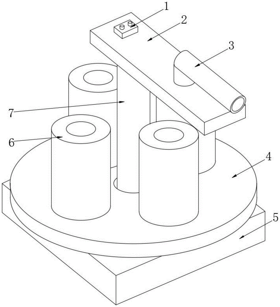
Figure 202120012766

The utility model relates to the technical field of spring washers, and discloses a multi-station unwinding machine for spring washers, comprising a base, a first support column is connected above the base, an inner ball of the base, the ball A turntable is connected to the outer side of the turntable, four second support columns are connected above the turntable, and a bobbin is connected to the outer side of the four second support columns and above the turntable. Column and ball, place the winding frame above the second support column, rotate the turntable, and use the connection between the ball and the first groove and the second groove to drive the winding frame above the turntable to rotate, It is beneficial to remove the winding frame on the original unwinding station, move the new winding frame to the lower part of the pulling mechanism, and carry out the next pulling work. It is time-consuming and labor-intensive to remove the winding frame at the station for replacement.

Figure 202120012766

Description

Multistation blowing machine for spring washer
Technical Field
The utility model relates to a spring washer technical field specifically is a multistation blowing machine for spring washer.
Background
The spring washer is widely applied to bearing and non-bearing structures of general mechanical products in the screw industry, is often called as an elastic cushion, is characterized by low cost and convenient installation, is suitable for parts with frequent assembly and disassembly, and needs a feeding machine to draw a raw material line for producing the spring washer in the production process of the spring washer.
There are multiple blowing machines in the existing market, but these blowing machines ubiquitous, only a blowing station, after a roll of former stockline was put, need dismantle the bobbin on former blowing station and change, waste time and energy, consequently, technical personnel in the field provide a multistation blowing machine for spring washer to solve the problem that proposes in the above-mentioned background art.
SUMMERY OF THE UTILITY MODEL
An object of the utility model is to provide a multistation blowing machine for spring washer to solve the problem that proposes among the above-mentioned background art.
In order to achieve the above object, the utility model provides a following technical scheme:
the utility model provides a multistation blowing machine for spring washer, includes the base, the top of base is connected with first support column, the second recess has been seted up to the inside of base, the internal connection of second recess has the ball, the outside of ball is connected with the carousel, the inside of carousel is including connecting the first recess in the ball outside, the second through-hole has been seted up to the inside of carousel, the second through-hole is connected with first support column, the top of carousel is connected with four second support columns, four the outside of second support column and the top that is located the carousel are connected with the bobbin.
As a further aspect of the present invention: the one end of first support column is connected with the backup pad, the bottom side of backup pad is connected with a set of guide rail, and is a set of the outside of guide rail is connected with drive mechanism, drive mechanism's inside is including connecting a set of U type frame in the guide rail outside, and a set of spout has been seted up to the inside of a set of U type frame, the spout is connected with the guide rail, and the inboard of a set of U type frame is connected with the spring, and is a set of the inside of U type frame is connected with first line ball roller and second line ball roller respectively, and is a set of the outside of U type frame is connected with a set of rotating electrical machines, and is a set of the one end of the inside output shaft of rotating electrical machines is connected with first line ball roller, second line ball roller respectively.
As a further aspect of the present invention: a first through hole is formed in the supporting plate, an L-shaped guide pipe is connected to the position, close to the first through hole, above the supporting plate, and a controller is connected to the position, close to the L-shaped guide pipe, above the supporting plate.
As a further aspect of the present invention: the turntable is rotatably connected with the base through the ball.
As a further aspect of the present invention: the position of the traction mechanism corresponds to the position of the first through hole.
As a further aspect of the present invention: the traction mechanism is connected with the guide rail in a sliding mode through the sliding groove.
Compared with the prior art, the beneficial effects of the utility model are that:
1. through the carousel, second support column and ball, place the bobbin in the top of second support column, rotate the carousel, utilize ball and first recess, the relation of connection between the second recess, the bobbin that drives the carousel top rotates, be favorable to removing the bobbin on former blowing station, remove new bobbin to drive mechanism's below, carry out traction work on next step, solved after a roll of former stockline has been put, need dismantle the bobbin on former blowing station and change, the problem of wasting time and energy.
2. Through drive mechanism, under the joining action of spring, make to have elastic connection between two U type framves, be favorable to adapting to a plurality of specification size raw materials lines between first line ball roller and the second line ball roller, pull the raw materials line of equidimension not, improve the practicality.
Drawings
FIG. 1 is a schematic structural view of a multi-station discharging machine for spring washers;
FIG. 2 is a side cross-sectional view of a multi-station feeder for spring washers;
fig. 3 is a top view of a pulling mechanism in a multi-station discharging machine for spring washers.
In the figure: 1. a controller; 2. a support plate; 21. a first through hole; 22. a guide rail; 3. an L-shaped conduit; 4. a turntable; 41. a first groove; 42. a second through hole; 5. a base; 51. a second groove; 6. a bobbin; 7. a first support column; 8. a traction mechanism; 81. a first wire pressing roller; 82. a chute; 83. a U-shaped frame; 84. a rotating electric machine; 85. a second line-pressing roller; 86. a spring; 9. a second support column; 10. and (4) a ball.
Detailed Description
Please refer to fig. 1-3, in the embodiment of the utility model, a multistation blowing machine for spring washer, including base 5, base 5's top is connected with first support column 7, second recess 51 has been seted up to base 5's inside, the internal connection of second recess 51 has ball 10, the outside of ball 10 is connected with carousel 4, the inside of carousel 4 is including connecting the first recess 41 in the ball 10 outside, second through-hole 42 has been seted up to the inside of carousel 4, second through-hole 42 is connected with first support column 7, the top of carousel 4 is connected with four second support columns 9, the outside of four second support columns 9 and the top that is located carousel 4 are connected with bobbin 6.
In fig. 1 and 2: one end of the first support column 7 is connected with the support plate 2, the bottom side of the support plate 2 is connected with a group of guide rails 22, the outer side of the group of guide rails 22 is connected with the traction mechanism 8, the interior of the traction mechanism 8 comprises a group of U-shaped frames 83 connected with the outer side of the guide rails 22, a group of sliding grooves 82 are formed in the group of U-shaped frames 83, the sliding grooves 82 are connected with the guide rails 22, the inner side of the group of U-shaped frames 83 is connected with springs 86, the interior of the group of U-shaped frames 83 is respectively connected with a first wire pressing roller 81 and a second wire pressing roller 85, the outer side of the group of U-shaped frames 83 is connected with a group of rotating motors 84, one end of an output shaft in the group of rotating motors 84 is respectively connected with the first wire pressing roller 81 and the second wire pressing roller 85, the raw material wire is placed in the first wire pressing roller 81 and the second wire pressing roller 85, the rotating motors 84 on both sides are started to drive the first wire pressing roller 81 and the second wire pressing roller 85 to rotate, the raw material line in the device is pulled.
In fig. 2: first through-hole 21 has been seted up to the inside of backup pad 2, and the position that the top of backup pad 2 is close to first through-hole 21 is connected with L type pipe 3, and the position that the top of backup pad 2 is close to L type pipe 3 is connected with controller 1, makes the raw materials line lead out along L type pipe 3 through first through-hole 21 and processes.
In fig. 1 and 2: the rotary table 4 is rotatably connected with the base 5 through the ball 10, the bobbin 6 is placed above the second supporting column 9, the rotary table 4 is rotated, the bobbin 6 above the rotary table 4 is driven to rotate by utilizing the connection relation between the ball 10 and the first groove 41 and the second groove 51, the bobbin 6 on the original material placing station is favorably moved away, a new bobbin 6 is moved to the lower part of the traction mechanism, and the traction work on the next step is carried out.
In fig. 2: the position of the drawing mechanism 8 corresponds to the position of the first through hole 21, so that the raw material wire drawn by the drawing mechanism 8 is led out along the first through hole 21.
In fig. 2 and 3: the traction mechanism 8 is slidably connected to the guide rail 22 through the sliding groove 82, and under the connecting action of the spring 86, the two U-shaped frames 83 are elastically connected to each other, so that when a raw material wire with a large specification is placed inside the first wire pressing roller 81 and the second wire pressing roller 85, the two U-shaped frames 83 are expanded to allow the sliding groove 82 above the two U-shaped frames 83 to slide along the guide rail 22.
The utility model discloses a theory of operation is: place the bobbin 6 in the top of second support column 9, rotate carousel 4, utilize the relation of connection between ball 10 and first recess 41, the second recess 51, it is rotatory to drive the bobbin 6 of carousel 4 top, be favorable to removing the bobbin 6 on the former blowing station, remove new bobbin 6 to the below of drive mechanism, place the raw materials line in the inside of first line ball roller 81, second line ball roller 85 afterwards, open the rotating electrical machines 84 of both sides, drive first line ball roller 81, second line ball roller 85 and rotate, pull its inside raw materials line, make the raw materials line lead out along L type pipe 3 through first through-hole 21 and process.
The above-mentioned, only be the concrete implementation of the preferred embodiment of the present invention, but the protection scope of the present invention is not limited thereto, and any person skilled in the art is in the technical scope of the present invention, according to the technical solution of the present invention and the utility model, the concept of which is equivalent to replace or change, should be covered within the protection scope of the present invention.

Claims (6)

1. The utility model provides a multistation blowing machine for spring washer, includes base (5), its characterized in that, the top of base (5) is connected with first support column (7), second recess (51) have been seted up to the inside of base (5), the internal connection of second recess (51) has ball (10), the outside of ball (10) is connected with carousel (4), the inside of carousel (4) is including connecting first recess (41) in ball (10) outside, second through-hole (42) have been seted up to the inside of carousel (4), second through-hole (42) are connected with first support column (7), the top of carousel (4) is connected with four second support column (9), four the outside of second support column (9) and the top that is located carousel (4) are connected with bobbin (6).
2. The multi-station discharging machine for the spring washers according to claim 1, characterized in that one end of the first support column (7) is connected with a support plate (2), the bottom side of the support plate (2) is connected with a set of guide rails (22), the outer side of the set of guide rails (22) is connected with a traction mechanism (8), the interior of the traction mechanism (8) comprises a set of U-shaped frames (83) connected to the outer side of the guide rails (22), a set of sliding grooves (82) are formed in the interior of the set of U-shaped frames (83), the sliding grooves (82) are connected with the guide rails (22), the inner side of the set of U-shaped frames (83) is connected with a spring (86), the interior of the set of U-shaped frames (83) is respectively connected with a first wire pressing roller (81) and a second wire pressing roller (85), the outer side of the set of U-shaped frames (83) is connected with a set of rotating motor (84), and one end of an output shaft in the set of the rotating motor (84) is respectively connected with the first wire pressing roller (81), The second wire pressing roller (85) is connected.
3. The multi-station discharging machine for the spring washers is characterized in that a first through hole (21) is formed in the supporting plate (2), an L-shaped guide pipe (3) is connected to the position, close to the first through hole (21), above the supporting plate (2), and a controller (1) is connected to the position, close to the L-shaped guide pipe (3), above the supporting plate (2).
4. The multi-station discharging machine for the spring washers is characterized in that the rotary disc (4) is rotatably connected with the base (5) through a round ball (10).
5. The multi-station discharging machine for spring washers according to claim 2, characterized in that the position of the traction mechanism (8) corresponds to the position of the first through hole (21).
6. The multi-station emptying machine for the spring washer as claimed in claim 2, wherein the traction mechanism (8) is slidably connected with the guide rail (22) through a sliding groove (82).
CN202120012766.7U 2021-01-05 2021-01-05 Multistation blowing machine for spring washer Expired - Fee Related CN214114452U (en)

Priority Applications (1)

Application Number Priority Date Filing Date Title
CN202120012766.7U CN214114452U (en) 2021-01-05 2021-01-05 Multistation blowing machine for spring washer

Applications Claiming Priority (1)

Application Number Priority Date Filing Date Title
CN202120012766.7U CN214114452U (en) 2021-01-05 2021-01-05 Multistation blowing machine for spring washer

Publications (1)

Publication Number Publication Date
CN214114452U true CN214114452U (en) 2021-09-03

Family

ID=77494715

Family Applications (1)

Application Number Title Priority Date Filing Date
CN202120012766.7U Expired - Fee Related CN214114452U (en) 2021-01-05 2021-01-05 Multistation blowing machine for spring washer

Country Status (1)

Country Link
CN (1) CN214114452U (en)

Cited By (1)

* Cited by examiner, † Cited by third party
Publication number Priority date Publication date Assignee Title
CN116119444A (en) * 2023-03-13 2023-05-16 浙江锐正汽车零部件有限公司 Novel multi-station discharging machine for spring washers

Cited By (1)

* Cited by examiner, † Cited by third party
Publication number Priority date Publication date Assignee Title
CN116119444A (en) * 2023-03-13 2023-05-16 浙江锐正汽车零部件有限公司 Novel multi-station discharging machine for spring washers

Similar Documents

Publication Publication Date Title
CN103624017B (en) Rotary scrubbing control device capable of cleaning bearings with different sizes
CN204369289U (en) A kind of admission machine
CN204847511U (en) Full -automatic plastic film quadruplex position coiling apparatus
CN107104563A (en) A kind of voltage plastic package motor rotor enters axle and moves back axle dual-purpose apparatus
CN111003585B (en) Directional rotating mechanical device of winding equipment
CN102672995B (en) Production device of powder molding press forming products
CN120347645B (en) An automated polishing device for producing magnetic head shells
CN105185570B (en) Full-automatic flat wire framework winding machine
CN204265808U (en) Reheating furnace stepping discharging machine
CN206373218U (en) Six method, apparatus in a kind of valve inside core body punching
CN110422411A (en) A roll-forming device with cutting function for anti-cracking cloth production
CN115194537A (en) Manipulator is transported to material
CN109759839A (en) Automatic rotating piece mounting device and working method thereof
CN220942917U (en) A punch press auxiliary device for automobile parts processing
CN220722980U (en) Coil stock quick replacement device
CN208878964U (en) A kind of bushing outer tube automatically in glue production line plastic roll device
CN216441998U (en) A device for automatic assembly of server components
CN217747848U (en) Full-automatic magnetic core coil point gum machine
CN203211901U (en) Automatic uniform feeding device
CN211404172U (en) Novel pipeline nylon sheath winding equipment
CN109968748B (en) a bending machine
CN223115958U (en) Single-head edge grinding machine
CN208527968U (en) A kind of pressure spring machine of self-feeding
CN218284335U (en) A horizontal automatic receiving machine for welded pipe unit
CN223229457U (en) 3D line scanning mechanism for appearance detection equipment

Legal Events

Date Code Title Description
GR01 Patent grant
GR01 Patent grant
TR01 Transfer of patent right

Effective date of registration: 20240918

Address after: Room 3103, Unit B, Building 95, Xiangyi Lanqiao Garden, Wujin District, Changzhou City, Jiangsu Province, China 213000

Patentee after: Deng Weiwei

Country or region after: China

Address before: 225700 Xingfu Road, Zhaoyang Industrial Park, Xinghua City, Taizhou City, Jiangsu Province

Patentee before: Jiangsu xingelastic Fastener Co.,Ltd.

Country or region before: China

TR01 Transfer of patent right
CF01 Termination of patent right due to non-payment of annual fee

Granted publication date: 20210903

CF01 Termination of patent right due to non-payment of annual fee