CN214100753U - A tubular busbar suspension clamp - Google Patents
A tubular busbar suspension clamp Download PDFInfo
- Publication number
- CN214100753U CN214100753U CN202023273751.0U CN202023273751U CN214100753U CN 214100753 U CN214100753 U CN 214100753U CN 202023273751 U CN202023273751 U CN 202023273751U CN 214100753 U CN214100753 U CN 214100753U
- Authority
- CN
- China
- Prior art keywords
- tubular busbar
- clamping part
- suspension clamp
- sides
- clamping
- Prior art date
- Legal status (The legal status is an assumption and is not a legal conclusion. Google has not performed a legal analysis and makes no representation as to the accuracy of the status listed.)
- Expired - Fee Related
Links
Images

Landscapes
- Clamps And Clips (AREA)
Abstract
本实用新型公开了一种管型母线悬吊线夹,涉及电力金具技术领域,包括一用于夹持管型母线的圆形夹持部,在夹持部的一侧上设有沿其轴线方向延伸的缺口,在夹持部上且位于缺口的两侧对称设有挂耳,两个挂耳通过锁紧件紧固,夹持部的底部设置成从中间向两边倾斜的斜面,在夹持部的内弧面上固定设有与夹持部平行的横向设置的凸条。本实用新型的凸条顶面组合成一个圆柱形,凸条的顶面与管型母线的接触为面接触,可以更加牢固的夹持管型母线,提高了管型母线和悬吊线夹之间的稳定性和安全性;本实用新型的凸条之间设有流水道,水从顶点向两端较低处流淌,不会产生积水,有效地避免了积水对管型母线造成的影响,延长了管型母线的使用寿命。

The utility model discloses a tubular busbar suspension clamp, which relates to the technical field of electric power fittings. The utility model comprises a circular clamping part for clamping the tubular busbar; The extended gap is provided with hanging lugs symmetrically on the clamping part and located on both sides of the gap. The two hanging lugs are fastened by locking parts. The bottom of the clamping part is set as a slope inclined from the middle to both sides. The inner arc surface of the part is fixed with a transversely arranged convex strip parallel to the clamping part. The top surface of the convex strip of the utility model is combined into a cylindrical shape, and the contact between the top surface of the convex strip and the tube-shaped busbar is surface contact, so that the tube-shaped busbar can be clamped more firmly, and the gap between the tube-shaped busbar and the suspension wire clamp is improved. The utility model is provided with water channels between the convex strips, and the water flows from the apex to the lower parts of the two ends, so that no accumulation of water is generated, and the influence of accumulation of water on the tubular busbar is effectively avoided. , extending the service life of the tubular busbar.
Description
技术领域technical field
本实用新型涉及电力金具技术领域,具体是一种管型母线悬吊线夹。The utility model relates to the technical field of electric power fittings, in particular to a tubular busbar suspension clamp.
背景技术Background technique
随着时代的发展,电力成为人们日常生活中必不可缺的一种常用的能源,它是将自然界的一次能源通过机械能装置转化成电力,再经输电、变电和配电将电力供应到各用户进行使用,而在电力建设过程中需要使用一种管型母线悬吊线夹对输送的电线进行限位固定,以保证输送电线在使用过程中的稳定性。现有的一种管型母线悬吊线夹由于本身结构的缺陷,在阴雨天气导致雨水容易在装置内部聚集,进而导致输电线在装置内部容易被雨水浸泡侵蚀,从而影响输电线的使用寿命。With the development of the times, electricity has become an indispensable and commonly used energy source in people's daily life. It converts primary energy in nature into electricity through mechanical energy devices, and then supplies electricity to various places through power transmission, transformation and distribution. Users use it, and in the process of power construction, a tubular busbar suspension clamp is required to limit and fix the transmission wire to ensure the stability of the transmission wire during use. Due to the structural defects of the existing tubular busbar suspension clamp, rainwater is easy to accumulate inside the device in rainy weather, and the transmission line is easily soaked and corroded by rainwater inside the device, thus affecting the service life of the transmission line.
授权公告号为CN 211655684 U的中国实用新型专利,公开了一种具有防水功能的一种管型母线悬吊线夹,包括主体以及设置在主体底部的连接座,所述主体由第一半圆固定件、第二半圆固定件以及连接组件组成,所述第一半圆固定件与所述第二半圆固定件内壁均采用多空结构,所述第一半圆固定件顶部设置有第一连接板,所述第二半圆固定件顶部设置有第二连接板,所述第一连接板一侧设置有连接螺栓。但是这种由两个半圆组成的夹持部主体,管型母线的重力一直给予下端的连接座,长时间下来,连接座断裂的概率增加,一方面影响了一种管型母线悬吊线夹的使用寿命,另一方面是夹持部与管型母线的接触为线接触,输电线的稳定性和安全性较低。The Chinese utility model patent with the authorization announcement number CN 211655684 U discloses a tubular busbar suspension clamp with waterproof function, comprising a main body and a connecting seat arranged at the bottom of the main body, the main body is formed by a first semicircular fixing member , a second semicircular fixing piece and a connecting component, the first semicircular fixing piece and the inner wall of the second semicircular fixing piece both adopt a hollow structure, the top of the first semicircular fixing piece is provided with a first connecting plate, the A second connecting plate is arranged on the top of the second semicircular fixing member, and a connecting bolt is arranged on one side of the first connecting plate. However, for the main body of the clamping part composed of two semicircles, the gravity of the tubular busbar is always given to the connecting seat at the lower end. After a long time, the probability of the connecting seat breaking increases. On the one hand, it affects the performance of a tubular busbar suspension clamp. Service life, on the other hand, the contact between the clamping part and the tubular busbar is line contact, and the stability and safety of the transmission line are low.
实用新型内容Utility model content
鉴于现有技术中存在的不足和缺陷,本实用新型提供了一种管型母线悬吊线夹,解决了背景技术中一种管型母线悬吊线夹使用寿命短,安全性和稳定性低的问题。In view of the deficiencies and defects in the prior art, the utility model provides a tubular busbar suspension clamp, which solves the problems of short service life, low safety and stability of the tubular busbar suspension clamp in the background art .
为了解决上述技术问题,本实用新型采用如下技术方案:一种管型母线悬吊线夹,包括一用于夹持管型母线的圆形夹持部,在所述夹持部的一侧上设有沿其轴线方向延伸的缺口,在所述夹持部上且位于所述缺口的两侧对称设有挂耳,两个所述挂耳通过锁紧件紧固,所述夹持部的底部设置成从中间向两边倾斜的凸面,在所述夹持部的内弧面上固定设有与所述夹持部平行的横向设置的凸条。In order to solve the above-mentioned technical problems, the present utility model adopts the following technical scheme: a tubular busbar suspension clamp, comprising a circular clamping portion for clamping the tubular busbar, and a side of the clamping portion is provided with a circular clamping portion. There is a notch extending along its axis direction, and hanging lugs are symmetrically arranged on both sides of the clamping part and the two sides of the notch are fastened by locking parts, and the bottom of the clamping part is The convex surface is arranged to be inclined from the middle to both sides, and the laterally arranged convex strips parallel to the clamping part are fixed on the inner arc surface of the clamping part.
作为本实用新型的进一步改进,所述凸条沿所述夹持部的内弧面均匀分布,在所述夹持部的倾斜处的内弧面上的凸条的高度为中间小两边大方便水从各凸条间流淌。As a further improvement of the present invention, the protruding strips are evenly distributed along the inner arc surface of the clamping portion, and the height of the protruding strips on the inner arc surface at the inclination of the clamping portion is small in the middle and large on both sides. Water flows from between the ridges.
作为本实用新型的进一步改进,所有所述凸条的顶面在一个圆上,且其圆心与在同一截面的所述夹持部的圆心为同一个,凸条的顶面可以组合成一个圆柱形。As a further improvement of the present invention, the top surfaces of all the protruding strips are on a circle, and the center of the circle is the same as the center of the clamping part in the same section, and the top surfaces of the protruding strips can be combined into a cylinder shape.
作为本实用新型的进一步改进,悬吊线夹采用高强度变形铝合金材料6063整体热挤压加工成型。As a further improvement of the present utility model, the suspension wire clip is formed by integral hot extrusion of high-strength deformed aluminum alloy material 6063.
与现有技术相比,本实用新型具有的有益效果为:本实用新型的凸条顶面组合成一个圆柱形,凸条的顶面与管型母线的接触为面接触,可以更加牢固的夹持管型母线,提高了管型母线和悬吊线夹之间的稳定性和安全性;本实用新型的凸条之间设有流水道,且在悬吊线夹的底侧容易积水处设置了顶部高于两侧的凹面,水从顶点向两端较低处流淌,不会产生积水,有效地避免了积水对管型母线造成的影响,延长了管型母线的使用寿命。Compared with the prior art, the utility model has the beneficial effects as follows: the top surface of the convex strip of the present invention is combined into a cylindrical shape, and the contact between the top surface of the convex strip and the tubular busbar is surface contact, which can clamp more firmly. Holding the tube-shaped busbar improves the stability and safety between the tube-shaped busbar and the suspension wire clip; the utility model is provided with a flow channel between the protruding bars, and the bottom side of the suspension wire clip is provided at the place where water is likely to accumulate. The top is higher than the concave surfaces on both sides, and the water flows from the apex to the lower parts of the two ends, so there will be no accumulation of water, which effectively avoids the influence of accumulated water on the tubular busbar and prolongs the service life of the tubular busbar.
附图说明Description of drawings
下面结合附图和具体实施方式对本实用新型作进一步的说明:The utility model will be further described below in conjunction with the accompanying drawings and specific embodiments:
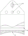
图1为本实用新型的的结构示意图;Fig. 1 is the structural representation of the utility model;
图2为图1的侧视图。FIG. 2 is a side view of FIG. 1 .
图中:100.管型母线,1.夹持部,2.挂耳,3.凸条,4.凹面,5.流水道,6.锁紧件。In the picture: 100. Tubular busbar, 1. Clamping part, 2. Hanging lug, 3. Raised strip, 4. Concave surface, 5. Flow channel, 6. Locking piece.
值得注意的是,在本实用新型的描述中,术语“中心”、“上”、“下”、“左”、“右”、“竖直”、“水平”、“内”、“外”等指示的方位或位置关系为基于附图所示的方位或位置关系,仅是为了便于描述本实用新型和简化描述,而不是指示或暗示所指的装置或元件必须具有特定的方位、以特定的方位构造和操作,因此不能理解为对本实用新型的限制。此外,术语“第一”、“第二”、“第三”仅用于描述目的,而不能理解为指示或暗示相对重要性。It is worth noting that in the description of the present invention, the terms "center", "upper", "lower", "left", "right", "vertical", "horizontal", "inner", "outer" The orientation or positional relationship indicated by etc. is based on the orientation or positional relationship shown in the accompanying drawings, which is only for the convenience of describing the present invention and simplifying the description, rather than indicating or implying that the referred device or element must have a specific orientation, with a specific orientation. Therefore, it should not be construed as a limitation on the present invention. Furthermore, the terms "first", "second", and "third" are used for descriptive purposes only and should not be construed to indicate or imply relative importance.
在本实用新型的描述中,需要说明的是,除非另有明确的规定和限定,术语“安装”、“相连”、“连接”应做广义理解,例如,可以是固定连接,也可以是可拆卸连接,或一体地连接;可以是机械连接,也可以是电连接;可以是直接相连,也可以通过中间媒介间接相连,可以是两个元件内部的连通。对于本领域的普通技术人员而言,可以具体情况理解上述术语在本实用新型中的具体含义。In the description of the present invention, it should be noted that, unless otherwise expressly specified and limited, the terms "installed", "connected" and "connected" should be understood in a broad sense, for example, it may be a fixed connection or a connectable connection. Detachable connection, or integral connection; may be mechanical connection or electrical connection; may be direct connection, or indirect connection through an intermediate medium, or internal communication between two components. For those of ordinary skill in the art, the specific meanings of the above terms in the present invention can be understood in specific situations.
具体实施方式Detailed ways
为了本实用新型的技术方案和有益效果更加清楚明白,下面结合附图和具体实施例对本实用新型进行进一步的详细说明,应当理解,此处所描述的具体实施方式仅用于理解本实用新型,并不用于限定本实用新型,本领域普通技术人员在没有做出创造性劳动前提下所获得的所有其他实施例,都属于本实用新型保护的范围。In order to make the technical solutions and beneficial effects of the present invention clearer, the present invention will be further described in detail below with reference to the accompanying drawings and specific embodiments. It should be understood that the specific embodiments described here are only used to understand the present invention, and It is not intended to limit the present invention, and all other embodiments obtained by those of ordinary skill in the art without creative work fall within the protection scope of the present invention.
请参阅图1和图2,本实用新型提供一种技术方案:一种管型母线悬吊线夹,包括一用于夹持管型母线100的圆形夹持部1,在夹持部1的一侧上设有沿其轴线方向延伸的缺口,在夹持部上且位于缺口的两侧对称设有挂耳2,两个挂耳2通过锁紧件6紧固,夹持部1的底部设置成从中间向两边倾斜的凸面4,在夹持部1的内弧面上固定设有与夹持部1平行的横向设置的凸条3。Please refer to FIG. 1 and FIG. 2 , the present utility model provides a technical solution: a tubular busbar suspension clamp, comprising a
优选地,凸条3沿夹持部1的内弧面均匀分布,在夹持部1的倾斜处的内弧面上的凸条3向下延伸距离为中间小两边大,方便水从各凸条间流淌。Preferably, the
优选地,所有凸条3的顶面在一个圆上,且其圆心与在同一截面的夹持部1的圆心为同一个,凸条的顶面可以组合成一个圆柱形。Preferably, the top surfaces of all the
优选地,两个凸条3之间设有流水道5,夹持部底侧的流水道设置为中间高两侧低,方便水从底部流出,不存有积水,有效的避免了积水对管型母线的影响,进而延长了管型母线的使用寿命。Preferably, a
优选地,悬吊线夹采用高强度变形铝合金材料6063整体热挤压加工成型,采用此种结构便于安装人员进行安装,不但降低了安装人员的劳动强度,并且还提高了安装效率。Preferably, the suspension wire clip is formed by integral hot extrusion of high-strength deformed aluminum alloy material 6063. Using this structure is convenient for installation personnel to install, which not only reduces the labor intensity of the installation personnel, but also improves the installation efficiency.
Claims (5)
Priority Applications (1)
| Application Number | Priority Date | Filing Date | Title |
|---|---|---|---|
| CN202023273751.0U CN214100753U (en) | 2020-12-30 | 2020-12-30 | A tubular busbar suspension clamp |
Applications Claiming Priority (1)
| Application Number | Priority Date | Filing Date | Title |
|---|---|---|---|
| CN202023273751.0U CN214100753U (en) | 2020-12-30 | 2020-12-30 | A tubular busbar suspension clamp |
Publications (1)
| Publication Number | Publication Date |
|---|---|
| CN214100753U true CN214100753U (en) | 2021-08-31 |
Family
ID=77435133
Family Applications (1)
| Application Number | Title | Priority Date | Filing Date |
|---|---|---|---|
| CN202023273751.0U Expired - Fee Related CN214100753U (en) | 2020-12-30 | 2020-12-30 | A tubular busbar suspension clamp |
Country Status (1)
| Country | Link |
|---|---|
| CN (1) | CN214100753U (en) |
-
2020
- 2020-12-30 CN CN202023273751.0U patent/CN214100753U/en not_active Expired - Fee Related
Similar Documents
| Publication | Publication Date | Title |
|---|---|---|
| CN206947555U (en) | A kind of soft graphite downlead device | |
| CN214383805U (en) | Large-scale aluminum cell upright post system | |
| CN210617855U (en) | Novel locomotive pantograph mounting structure | |
| CN210976577U (en) | Aluminum frame covers moulds building templates | |
| CN205269915U (en) | Cast wet -type electrostatic precipitator's spiral corona wire | |
| CN213927683U (en) | Solar energy supply device of bus stop | |
| CN105048130B (en) | A kind of division wire clamp gold utensil | |
| CN207124598U (en) | A kind of photovoltaic module briquetting and the photovoltaic generating system using the briquetting | |
| CN211579004U (en) | Copper-aluminum transition wire clamp | |
| CN211266344U (en) | Electrical cable fixing frame | |
| CN211663101U (en) | Contact wire lower anchor device fixing structure | |
| CN217406157U (en) | Special clamp for intermediate joint of medium-voltage cable | |
| CN208337127U (en) | Energy-saving building roof lightning arrester | |
| CN209472325U (en) | A kind of photovoltaic power station photovoltaic client cables fixed structure | |
| CN213027312U (en) | A weak current pipeline connection device | |
| CN219804792U (en) | Quick mounting structure of wet-type electric precipitation negative pole line bottom | |
| CN217527847U (en) | Flow-equalizing type concave-convex sleeve of electrostatic dust collector | |
| CN218101716U (en) | A conversion fitting and a conductor-overhead line conversion system in a converter station | |
| CN215563893U (en) | Wind-resistant clamp for roof panel | |
| CN214204225U (en) | Brush board assembly convenient to equipment | |
| CN214674230U (en) | Facade anchoring support | |
| CN214255437U (en) | Temporary rest device for horizontal wire operation | |
| CN220067284U (en) | A support frame for photovoltaic modules | |
| CN215070446U (en) | Transition plate for power transmission | |
| CN212725640U (en) | Negative electrode battery bolt of automobile storage battery |
Legal Events
| Date | Code | Title | Description |
|---|---|---|---|
| GR01 | Patent grant | ||
| GR01 | Patent grant | ||
| CF01 | Termination of patent right due to non-payment of annual fee | ||
| CF01 | Termination of patent right due to non-payment of annual fee |
Granted publication date: 20210831 |