CN214091060U - Operation platform for adjusting position degree of rod end plate mounting hole - Google Patents
Operation platform for adjusting position degree of rod end plate mounting hole Download PDFInfo
- Publication number
- CN214091060U CN214091060U CN202022481526.XU CN202022481526U CN214091060U CN 214091060 U CN214091060 U CN 214091060U CN 202022481526 U CN202022481526 U CN 202022481526U CN 214091060 U CN214091060 U CN 214091060U
- Authority
- CN
- China
- Prior art keywords
- frame
- base
- end plate
- mounting hole
- operation platform
- Prior art date
- Legal status (The legal status is an assumption and is not a legal conclusion. Google has not performed a legal analysis and makes no representation as to the accuracy of the status listed.)
- Active
Links
- 230000003014 reinforcing effect Effects 0.000 claims description 3
- 229910000831 Steel Inorganic materials 0.000 abstract description 17
- 239000010959 steel Substances 0.000 abstract description 17
- 238000010276 construction Methods 0.000 abstract description 5
- 238000000034 method Methods 0.000 abstract description 4
- 238000010923 batch production Methods 0.000 abstract description 2
- 238000009434 installation Methods 0.000 description 5
- 238000003466 welding Methods 0.000 description 4
- 238000004519 manufacturing process Methods 0.000 description 2
- 230000009286 beneficial effect Effects 0.000 description 1
- 238000010586 diagram Methods 0.000 description 1
- 238000011900 installation process Methods 0.000 description 1
- 238000012986 modification Methods 0.000 description 1
- 230000004048 modification Effects 0.000 description 1
- 238000012797 qualification Methods 0.000 description 1
- 239000002699 waste material Substances 0.000 description 1
Images


Landscapes
- Butt Welding And Welding Of Specific Article (AREA)
Abstract
The utility model belongs to the technical field of the steel construction, in particular to operation platform of adjustment member end plate mounting hole site degree of putting, including base, guide wheel carrier, removal frame and mount, remove the frame and sit on the base and can follow the base through the gyro wheel and remove, remove the one end that the frame is located the base, the mount is located the other end of base, the relative position that removes frame and mount is equipped with end plate hole site template respectively, removes and is equipped with two cranes between the base between frame and the mount. Compared with the prior art, the utility model has the advantages that: 1) the method is suitable for batch production of products with the same specification and model and products with high straightness requirement after the rod pieces are installed, and the qualified rate is 100%; 2) simple structure, convenient adjustment, safety and reliability, and can be repeatedly used. 3) The problems of low efficiency and high rejection rate caused by insufficient operation experience of operators on the equipment are effectively reduced, and the working efficiency is improved.
Description
Technical Field
The utility model belongs to the technical field of the steel construction, in particular to operation platform of adjustment member end plate mounting hole site degree.
Background
In the engineering construction process, the two ends of the rod are always in a bolt connection structure form, and the holes of the two end plates are required to be kept on the same axis, namely the holes on the two sides are ensured to be concentric. The same hole needs to reach 100% to ensure the smooth installation. The same hole of the two end plates is usually manually controlled during manufacturing, and the concentricity and the same hole rate of the final forming of the rod piece are influenced by personnel quality, field problems, tools and the like. In addition, in the installation construction, one end plate and the two end plates can not ensure the same hole, and the deflection angle of the rod piece can be generated in the installation process, so that the installation can not be carried out smoothly. To address such errors, the rods are typically removed, the ground is re-drilled or the wrong end plate is cut and re-welded. This causes a delay in the construction, additional expenditure for mechanical and manual costs, and unnecessary waste.
Disclosure of Invention
The utility model aims at providing an operation platform of adjustment member end plate mounting hole site degree overcomes prior art's is not enough, designs and makes an operation platform, can make the mounting hole of both sides end plate align with the direction of member fast when the installation, improves the straightness accuracy of mounting hole on the member, makes on the member can be installed smoothly to the end plate, reduces the auxiliary operation time, improves work efficiency.
In order to achieve the above purpose, the utility model adopts the following technical scheme:
the utility model provides an operation platform of adjustment member end plate mounting hole site degree of putting, its characterized in that includes base, guide pulley frame, removes frame and mount, removes the frame and sits on the base and can follow the base through the gyro wheel and remove, removes the one end that the frame is located the base, and the mount is located the other end of base, the relative position that removes frame and mount is equipped with end plate hole site template respectively, removes to be equipped with two erectors between the base between frame and the mount.
Further, including shell, frame, flexible drive arrangement and removal bedplate in the removal frame, be equipped with the frame in the shell, be equipped with flexible drive arrangement on the frame, flexible drive arrangement's front end is connected with the removal bedplate, be equipped with end plate hole site template on the removal bedplate, one side of removal frame is equipped with the guide wheel frame, be connected through the leading wheel between the lateral wall of guide wheel frame and base, the opposite side of removal frame is equipped with the walking motor, the output shaft end of walking motor meshes with the rack of locating on the base opposite side lateral wall mutually through the gear, the shell bottom is connected with the gyro wheel through the gyro wheel axle.
Furthermore, the base is a welded structure formed by two box-shaped bottom beams I and two bottom beams II through a plurality of connecting plates.
Furthermore, the lifting frame comprises a lifting driving device and a supporting plate arranged at the end part of the lifting driving device.
Furthermore, the telescopic driving device and the lifting driving device are hydraulic cylinders, air cylinders or electric push rods.
Furthermore, the parallelism between the upper plane and the bottom surface of the base is +/-1 mm, the perpendicularity between the end plate hole site template and the bottom surface is +/-0.5 mm, and the length deviation value of the diagonal line from the central point of the end part of the first bottom beam to the central point of the tail part of the second bottom beam is +/-2 mm.
Furthermore, be equipped with the fixed seat board in the mount, the fixed seat board is connected with the base through the fixed bolster, is equipped with a plurality of rib plate between the back of fixed seat board and the fixed bolster, is provided with end plate hole site template on the fixed seat board.
Compared with the prior art, the beneficial effects of the utility model are that: 1) the method is particularly suitable for batch production of products with the same specification and model and products with high straightness requirement after the rod pieces are installed, and the qualified rate is 100%; 2) simple structure, convenient adjustment, safety and reliability, and can be repeatedly used. 3) The problem of low efficiency and high rejection rate that the experience of operating personnel to equipment operation is not enough because of having effectively reduced, through improving the straightness accuracy of the last mounting hole of member, for the good basis is laid down in going on smoothly of installation afterwards, can make both sides end plate install the member fast on, do not receive operational environment restriction, the auxiliary operation time that has significantly reduced has improved work efficiency.
Drawings
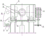
Fig. 1 is a schematic structural diagram of an embodiment of the present invention.
Fig. 2 is a view a-a in fig. 1.
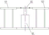
Fig. 3 is a view B-B in fig. 1.
Fig. 4 is a view C-C in fig. 1.
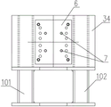
Fig. 5 is a view D-D in fig. 1.
In the figure: 1-a base; 2-a guide wheel; 3-moving the frame; 4-a fixing frame; 5-a roller; 6-end plate hole site template; 7-a positioning pin; 8-lifting frame; 9-a walking motor; 10-a gear; 11-a rack; 12-a connecting plate; 13-an end plate; 14-a rod member; 15-manual fixing pin; 31-a housing; 32-a frame; 33-telescopic drive means; 34-moving the seat plate; 35-a guide wheel frame; 36-roller shaft; 41-fixed seat board; 42-a fixed support; 43-a reinforcing floor; 81-lifting driving device; 82-a pallet; 101-base one; 102-base two.
Detailed Description
The technical solutions in the embodiments of the present invention will be described clearly and completely with reference to the accompanying drawings in the present application, and it is obvious that the described embodiments are only some embodiments of the present invention, not all embodiments. Based on the embodiments in the present invention, all other embodiments obtained by a person skilled in the art without creative work belong to the protection scope of the present invention.
See fig. 1-5, be the utility model relates to an operation platform embodiment schematic structure that can straighten welding deformation's member, including base 1, guide wheel carrier 35, remove frame 3 and mount 4, remove frame 3 and sit on base 1 and can follow base 1 through gyro wheel 5 and remove, remove the one end that frame 3 is located base 1, mount 4 is located base 1's the other end, remove frame 3 and mount 4 relative position department and be equipped with end plate hole site template 6, be equipped with locating pin 7 on the end plate hole site template 6, be equipped with two cranes 8 between base 1 between removing frame 3 and the mount 4, be equipped with manual fixed pin 15 and flexible drive arrangement 33 on the removal frame. The base 1 is a welded structure formed by two box- shaped bottom beams 101 and 102 through a plurality of connecting plates. The parallelism between the upper surface and the bottom surface of the base 1 is +/-1 mm, the perpendicularity between the end plate hole site template 6 and the bottom surface is +/-0.5 mm, and the length deviation value of the diagonal line from the central point of one end part of the bottom beam to the central point of the two tail parts of the bottom beam is +/-2 mm.
The lifting frame 8 comprises a lifting driving device 81 and a supporting plate 82 arranged at the end part of the lifting driving device 81. The height of the rod piece is adjusted by adjusting the height of the lifting frame.
The fixing frame 4 is provided with a fixing seat plate 41, the fixing seat plate 41 is connected with the base 1 through a fixing bracket 42, a plurality of reinforcing rib plates 43 are arranged between the back surface of the fixing seat plate 41 and the fixing bracket 42, and the fixing seat plate 41 is provided with an end plate hole site template 6.
The movable frame 3 comprises a shell 31, a frame 32, a telescopic driving device 33 and a movable seat plate 34, the frame 32 is arranged in the shell 31, the telescopic driving device 33 is arranged on the frame 32, the front end of the telescopic driving device 33 is connected with the movable seat plate 34, the movable seat plate 34 is provided with an end plate hole site template 6, the bottom of the shell 31 is connected with a roller 5 through a roller shaft 36, and the advance or retreat of the movable frame 3 is adjusted along with the length of a rod piece. One side of the movable frame 3 is provided with a guide wheel frame 35, the guide wheel frame 35 is connected with the side wall of the base 1 through a guide wheel 2, the other side of the movable frame 3 is provided with a walking motor 9, and the output shaft end of the walking motor 9 is meshed with a rack 11 arranged on the side wall of the other side of the base through a gear 10.
In the embodiment, the telescopic driving device 33 and the lifting driving device 81 are hydraulic cylinders, and may be air cylinders or electric push rods.
The utility model relates to an operation platform embodiment of adjustment member end plate concentricity and same porosity can be applicable to and use any kind in circular steel tube, square steel pipe, H shape steel, angle steel or the channel-section steel as the member, the condition of end plate is connected at both ends. In this embodiment, the manufacturing of the same-hole rod member using H-shaped steel as an example specifically includes the following steps:
1) selecting end plate hole site templates 6 according to the number of holes and specifications on end plates on two sides of the H-shaped steel (rod piece 14) to be manufactured, placing positioning pins 7 according to the number of holes and arrangement positions, placing the end plate hole site templates 6 on a fixed seat plate 41 and a movable seat plate 34 on a fixed frame 4 and a movable frame 3 respectively, and connecting firmly by bolts;
2) respectively placing end plates 13 required to be placed on two sides of the H-shaped steel on the end plate hole site templates 6 of the fixed base plate and the movable base plate and keeping clamping, placing the H-shaped steel on a supporting plate of the lifting frame, and adjusting the height of the supporting plate to enable the supporting plate to be concentric and coaxial with the end plate hole site templates 6; and the movable frame 3 is moved according to the length of the H-shaped steel, when the movable frame moves, the manual fixing pin 15 is retracted, the manual fixing pin 15 falls and is inserted into a proper hole on the base at a proper position, the movable frame is fixed so as not to move any more, and then the distance of the H-shaped steel is finely adjusted by using the telescopic driving device 33.
3) Controlling the movable frame 3 to move towards the fixed frame 4 until one end plate 13 reaches the combination position and is superposed with the rod piece, and then fixing the seam by spot welding; the adjusting and moving frame operates to push and clamp the H-shaped steel, and the whole H-shaped steel and the end plate are concentric because the H-shaped steel and the end plate are concentric through the front adjustment. Because the positioning pins on the dies on the two sides are concentric, the holes of the end plates arranged on the dies are 100 percent of same holes;
4) and (3) taking the two end plates off the end plate hole site template 6 respectively, lifting the rod piece 14 to a welding area, and continuously welding the matching seam between the rod piece 14 and the end plate 13. The concentricity and the same porosity of the H-shaped steel combined member finally manufactured through the processes can reach 100 percent of qualification.
The above embodiments are merely specific examples selected for the purpose of illustrating the objects, technical solutions and advantages of the present invention in detail, but should not limit the scope of the invention, and all modifications, equivalents and improvements made without departing from the spirit and principles of the present invention should fall within the scope of the invention.
Claims (7)
1. The utility model provides an operation platform of adjustment member end plate mounting hole site degree of putting, its characterized in that includes base, guide pulley frame, removes frame and mount, removes the frame and sits on the base and can follow the base through the gyro wheel and remove, removes the one end that the frame is located the base, and the mount is located the other end of base, the relative position that removes frame and mount is equipped with end plate hole site template respectively, removes to be equipped with two erectors between the base between frame and the mount.
2. The operation platform for adjusting the positional tolerance of the rod end plate mounting hole according to claim 1, wherein: the movable rack comprises a shell, a frame, a telescopic driving device and a movable base plate, wherein the frame is arranged in the shell, the telescopic driving device is arranged on the frame, the front end of the telescopic driving device is connected with the movable base plate, an end plate hole site template is arranged on the movable base plate, a guide wheel frame is arranged on one side of the movable rack, the guide wheel frame is connected with the side wall of the base through a guide wheel, a walking motor is arranged on the other side of the movable rack, the output shaft end of the walking motor is meshed with a rack arranged on the side wall of the other side of the base through a gear, and the bottom of the shell is connected with a roller through a roller shaft.
3. The operation platform for adjusting the positional tolerance of the rod end plate mounting hole according to claim 1, wherein: the base is a welded structure formed by two box-shaped bottom beams I and two bottom beams II through a plurality of connecting plates.
4. The operation platform for adjusting the positional tolerance of the rod end plate mounting hole according to claim 1, wherein: the lifting frame comprises a lifting driving device and a supporting plate arranged at the end part of the lifting driving device.
5. The operation platform for adjusting the positional tolerance of the rod end plate mounting hole according to claim 2, wherein: the telescopic driving device and the lifting driving device are hydraulic cylinders, air cylinders or electric push rods.
6. The operation platform for adjusting the positional tolerance of the rod end plate mounting hole according to claim 3, wherein: the parallelism between the upper plane and the bottom surface of the base is within +/-1 mm, the perpendicularity between the end plate hole site template and the bottom surface is within +/-0.5 mm, and the length deviation value of the diagonal line from the central point of one end part of the bottom beam to the central point of the two tail parts of the bottom beam is within +/-2 mm.
7. The operation platform for adjusting the positional tolerance of the rod end plate mounting hole according to claim 1, wherein: the fixing frame is internally provided with a fixing seat board, the fixing seat board is connected with the base through a fixing support, a plurality of reinforcing rib plates are arranged between the back face of the fixing seat board and the fixing support, and an end plate hole site template is arranged on the fixing seat board.
Priority Applications (1)
| Application Number | Priority Date | Filing Date | Title |
|---|---|---|---|
| CN202022481526.XU CN214091060U (en) | 2020-11-02 | 2020-11-02 | Operation platform for adjusting position degree of rod end plate mounting hole |
Applications Claiming Priority (1)
| Application Number | Priority Date | Filing Date | Title |
|---|---|---|---|
| CN202022481526.XU CN214091060U (en) | 2020-11-02 | 2020-11-02 | Operation platform for adjusting position degree of rod end plate mounting hole |
Publications (1)
| Publication Number | Publication Date |
|---|---|
| CN214091060U true CN214091060U (en) | 2021-08-31 |
Family
ID=77447319
Family Applications (1)
| Application Number | Title | Priority Date | Filing Date |
|---|---|---|---|
| CN202022481526.XU Active CN214091060U (en) | 2020-11-02 | 2020-11-02 | Operation platform for adjusting position degree of rod end plate mounting hole |
Country Status (1)
| Country | Link |
|---|---|
| CN (1) | CN214091060U (en) |
Cited By (1)
| Publication number | Priority date | Publication date | Assignee | Title |
|---|---|---|---|---|
| CN112196289A (en) * | 2020-11-02 | 2021-01-08 | 中国三冶集团有限公司 | Operating platform for adjusting position degree of rod piece end plate mounting hole and operating method thereof |
-
2020
- 2020-11-02 CN CN202022481526.XU patent/CN214091060U/en active Active
Cited By (2)
| Publication number | Priority date | Publication date | Assignee | Title |
|---|---|---|---|---|
| CN112196289A (en) * | 2020-11-02 | 2021-01-08 | 中国三冶集团有限公司 | Operating platform for adjusting position degree of rod piece end plate mounting hole and operating method thereof |
| CN112196289B (en) * | 2020-11-02 | 2024-07-16 | 中国三冶集团有限公司 | Operation platform for adjusting position degree of rod piece end plate mounting hole and operation method thereof |
Similar Documents
| Publication | Publication Date | Title |
|---|---|---|
| CN202701661U (en) | Assembly and welding tool for bogie frame beams | |
| CN112196289A (en) | Operating platform for adjusting position degree of rod piece end plate mounting hole and operating method thereof | |
| CN219113275U (en) | Frame welding tool | |
| CN212526566U (en) | Beam column welding robot | |
| CN210361134U (en) | Replacement device for balance beam of section steel roughing mill | |
| CN110328488B (en) | Square water tank welding frock | |
| CN221389465U (en) | Production line of excavator platform | |
| CN220679086U (en) | Automatic change punching press production line vacancy transition device | |
| CN219131335U (en) | Three-station manual positioner | |
| CN113770571A (en) | Beam column welding robot | |
| CN115255851B (en) | Box arm assembly equipment and box arm assembly method | |
| CN216370869U (en) | Welding workstation for assembling side plates of pump truck arm support | |
| CN217325059U (en) | Three-dimensional beam falling device convenient to move | |
| CN213616361U (en) | Multifunctional automobile frame longitudinal beam clamping and supporting platform | |
| CN112474811B (en) | Quick replacing device for finish rolling bending cylinder | |
| CN213104094U (en) | Stamping die capable of safely taking part | |
| CN220217470U (en) | Adjustable gantry bracket for gantry machining | |
| CN212600168U (en) | Header tube panel modularization manufacturing device | |
| CN113275814A (en) | Processing method of framework cross beam assembly tool of contact net comprehensive operation vehicle | |
| CN110253493B (en) | Profile steel roughing mill balance beam replacement device and profile steel roughing mill balance beam replacement method | |
| CN207386897U (en) | CT equipment pedestal list leg weld mold | |
| CN223820129U (en) | A sheet metal processing platform | |
| CN105252191A (en) | Welding fixture and welding method of steel structure module house stand column | |
| CN221370441U (en) | False flange jacking frock of steel-pipe pile | |
| CN119429019B (en) | A device for assembling curved hull frames and railings. |
Legal Events
| Date | Code | Title | Description |
|---|---|---|---|
| GR01 | Patent grant | ||
| GR01 | Patent grant |