CN214089830U - Energy-saving novel building pile capable of improving working efficiency - Google Patents
Energy-saving novel building pile capable of improving working efficiency Download PDFInfo
- Publication number
- CN214089830U CN214089830U CN202023057751.7U CN202023057751U CN214089830U CN 214089830 U CN214089830 U CN 214089830U CN 202023057751 U CN202023057751 U CN 202023057751U CN 214089830 U CN214089830 U CN 214089830U
- Authority
- CN
- China
- Prior art keywords
- fixedly connected
- pile body
- pile
- fixed plate
- energy
- Prior art date
- Legal status (The legal status is an assumption and is not a legal conclusion. Google has not performed a legal analysis and makes no representation as to the accuracy of the status listed.)
- Expired - Fee Related
Links
- 230000007246 mechanism Effects 0.000 claims abstract description 38
- 230000003014 reinforcing effect Effects 0.000 claims abstract description 21
- 239000002689 soil Substances 0.000 abstract description 3
- 230000009286 beneficial effect Effects 0.000 abstract 1
- 230000005012 migration Effects 0.000 description 4
- 238000013508 migration Methods 0.000 description 4
- 230000009471 action Effects 0.000 description 1
- 230000004075 alteration Effects 0.000 description 1
- 238000010586 diagram Methods 0.000 description 1
- 230000000694 effects Effects 0.000 description 1
- 238000000034 method Methods 0.000 description 1
- 230000004048 modification Effects 0.000 description 1
- 238000012986 modification Methods 0.000 description 1
- 230000008569 process Effects 0.000 description 1
- 238000005728 strengthening Methods 0.000 description 1
- 238000006467 substitution reaction Methods 0.000 description 1
Images
Landscapes
- Piles And Underground Anchors (AREA)
Abstract
The utility model discloses an improve work efficiency's novel building pile of energy-saving, including the pile body, the bottom fixedly connected with pile head of pile body, the top inner wall fixedly connected with actuating mechanism of pile body, actuating mechanism's output shaft fixedly connected with threaded rod, the surface screw thread of threaded rod is connected with the thread bush, the equal fixed connection fixed plate one in both ends of thread bush, fixed plate one is kept away from one side symmetric connection of thread bush has the movable rod, the movable rod is kept away from the one end swing joint of fixed plate one has fixed plate two, one side fixedly connected with reinforcing mechanism of fixed plate two, the inside fixedly connected with baffle of pile body, the top cover of pile body is equipped with the sleeve, telescopic top fixedly connected with roof, beneficial effect: can be under actuating mechanism's drive for the threaded rod rotates, thereby makes two drive reinforcing mechanism of fixed plate remove, and inserts into soil, increases the fastness of pile body.
Description
Technical Field
The utility model relates to a building pile field particularly, relates to an improve novel building pile of energy-saving of work efficiency.
Background
Traditional building pile, no location structure, length is fixed, application scope is little, squeeze into the ground after, only rely on pile body surface fixed with the frictional force of earth, often appear fixed not firm, it is not hard up easily, phenomenons such as skid, can not play fine fixed position effect to building and equipment, influence the temperature and the safety of building and equipment, current device is in order to increase the fastness of pile body, be equipped with parts such as arch in the pile body outside, this kind of mechanism can increase pile body fastness, but also improved the degree of difficulty of pile simultaneously, and current building pile is lower at work efficiency.
An effective solution to the problems in the related art has not been proposed yet.
SUMMERY OF THE UTILITY MODEL
The technical task of the utility model is to above not enough, provide an energy-saving novel building pile who improves work efficiency, solve the problem that the background art provided.
In order to achieve the above object, the utility model provides a following technical scheme: the utility model provides an improve novel building pile of energy-saving of work efficiency, includes the pile body, the bottom fixedly connected with pile head of pile body, the top inner wall fixedly connected with actuating mechanism of pile body, actuating mechanism's output shaft fixedly connected with threaded rod, the surface threaded connection of threaded rod has the thread bush, the equal fixedly connected with fixed plate one in both ends of thread bush, fixed plate one is kept away from one side symmetric connection of thread bush has the movable rod, the movable rod is kept away from the one end swing joint of fixed plate one has fixed plate two, one side fixedly connected with strengthening mechanism of fixed plate two, the inside fixedly connected with baffle of pile body, the top of baffle with be equipped with slide mechanism between the fixed plate two, the top cover of pile body is equipped with the sleeve, telescopic top fixedly connected with roof.
Further, actuating mechanism includes the motor, the top inner wall fixedly connected with motor of pile body, the output shaft of motor with threaded rod fixed connection.
Further, the reinforcing mechanism comprises reinforcing rods and openings, a plurality of reinforcing rods are fixedly connected to one side of the second fixing plate, a plurality of openings are formed in the two sides of the pile body, and the openings are matched with the reinforcing rods.
Furthermore, slide mechanism includes spout, slider and slide bar, the spout has been seted up to the top symmetry of baffle, the inside sliding connection of spout has the slider, the top of slider pass through the slide bar with two fixed connection of fixed plate.
Furthermore, the movable rod is movably connected with the first fixed plate and the second fixed plate through movable shafts.
Further, a spring is connected between the sleeve and the pile body.
Furthermore, the inside of the pile head is provided with a through hole.
The utility model has the advantages that:
1. this energy-saving novel building pile through setting up threaded rod, thread bush, fixed plate one, movable rod, fixed plate two, baffle, sleeve, roof, reinforcing mechanism and actuating mechanism, can be under actuating mechanism's drive for the threaded rod rotates, thereby makes fixed plate two drive reinforcing mechanism remove, and inserts into soil, increases the fastness of the pile body.
2. Through setting up slide mechanism, not only can be convenient for fixed plate two carry out horizontal migration, also can restrict the screw thread cover and rotate along with the rotation of threaded rod when removing simultaneously to make fixed plate two remove more stable.
3. Through setting up the spring, can enough slow down the vibrations that the pile produced, also can improve the efficiency of pile under the spring action of spring.
Drawings
In order to more clearly illustrate the embodiments of the present invention or the technical solutions in the prior art, the drawings required to be used in the embodiments will be briefly described below, and it is obvious that the drawings in the following description are only some embodiments of the present invention, and for those skilled in the art, other drawings can be obtained according to these drawings without creative efforts.
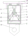
Fig. 1 is a schematic structural diagram of an energy-saving novel building pile for improving working efficiency according to an embodiment of the utility model;
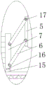
fig. 2 is an enlarged view at a in fig. 1.
Reference numerals:
1. a pile body; 2. pile head; 3. a threaded rod; 4. a threaded sleeve; 5. a first fixing plate; 6. a movable rod; 7. a second fixing plate; 8. a baffle plate; 9. a sleeve; 10. a top plate; 11. a motor; 12. a reinforcing rod; 13. an opening; 14. a chute; 15. a slider; 16. a slide bar; 17. a movable shaft; 18. a spring; 19. and (6) perforating.
Detailed Description
The invention will be further explained with reference to the drawings and the specific embodiments.
The first embodiment is as follows:
referring to fig. 1-2, according to an embodiment of the present invention, an energy-saving building pile for improving work efficiency includes a pile body 1, a pile head 2 is fixedly connected to a bottom end of the pile body 1, a driving mechanism is fixedly connected to an inner wall of a top end of the pile body 1, a threaded rod 3 is fixedly connected to an output shaft of the driving mechanism, a threaded sleeve 4 is connected to a surface thread of the threaded rod 3, a first fixing plate 5 is fixedly connected to both ends of the threaded sleeve 4, a movable rod 6 is symmetrically connected to a side of the first fixing plate 5 away from the threaded sleeve 4, a second fixing plate 7 is movably connected to a end of the movable rod 6 away from the first fixing plate 5, a reinforcing mechanism is fixedly connected to a side of the second fixing plate 7, a baffle 8 is fixedly connected to an inside of the pile body 1, and a sliding mechanism is disposed between a top end of the baffle 8 and the second fixing plate 7, the top end of the pile body 1 is sleeved with a sleeve 9, and the top end of the sleeve 9 is fixedly connected with a top plate 10.
Through the above technical scheme of the utility model, can be under actuating mechanism's drive for threaded rod 3 rotates, thereby makes two 7 drive reinforcing mechanism of fixed plate remove, and inserts into soil, increases pile body 1's fastness.
Example two:
referring to fig. 1-2, for the driving mechanism, the driving mechanism includes a motor 11, the motor 11 is fixedly connected to the inner wall of the top end of the pile body 1, the output shaft of the motor 11 is fixedly connected to the threaded rod 3, for the reinforcing mechanism, the reinforcing mechanism includes a reinforcing rod 12 and an opening 13, a plurality of reinforcing rods 12 are fixedly connected to one side of the second fixing plate 7, a plurality of openings 13 are respectively formed on both sides of the pile body 1, the opening 13 is matched with the reinforcing rod 12, for the sliding mechanism, the sliding mechanism includes a sliding chute 14, a sliding block 15 and a sliding rod 16, the sliding chute 14 is symmetrically formed at the top end of the baffle plate 8, a sliding block 15 is slidably connected to the inside of the sliding chute 14, the top end of the sliding block 15 is fixedly connected to the second fixing plate 7 through the sliding rod 16, and for the movable rod 6, the movable rod 6 is movably connected to the first fixing plate 5 and the second fixing plate 7 through a movable shaft 17 The sleeve 9 is connected to the pile body 1 through a spring 18, and the pile head 2 is provided with a through hole 19 inside the pile head 2.
Through the above technical scheme of the utility model, set up slide mechanism, not only can be convenient for two 7 of fixed plates carry out horizontal migration, also can restrict simultaneously the thread bush 4 and not rotate along with the rotation of threaded rod 3 when removing to make more stable that two 7 of fixed plates removed.
For the convenience of understanding the technical solution of the present invention, the following detailed description is made on the working principle or the operation mode of the present invention in the practical process.
When in actual application, squeeze into earth with pile body 1 through external force earlier, restart motor 11, motor 11 drives threaded rod 3 and rotates, threaded rod 3 drives thread bush 4 and moves down, thread bush 4 drives fixed plate 5 and moves, fixed plate 5 drives fixed plate two 7 through movable rod 6 and carries out horizontal migration, through spout 14 and slider 15 and slide bar 16, not only can be convenient for fixed plate two 7 carry out horizontal migration, also can restrict thread bush 4 and rotate along with threaded rod 3's rotation when moving simultaneously, thereby make the more stable that fixed plate two 7 removed, fixed plate two 7 drive anchor strut 12 outwards, anchor strut 12 passes opening 13 and gets into in the earth, thereby can increase the stability of pile body 1, and anchor strut 12 is located pile body 1's inside, can not increase pile body 1's resistance, make it more efficient.
Although embodiments of the present invention have been shown and described, it will be appreciated by those skilled in the art that changes, modifications, substitutions and alterations can be made in these embodiments without departing from the principles and spirit of the invention, the scope of which is defined in the appended claims and their equivalents.
Claims (7)
1. The energy-saving novel building pile capable of improving the working efficiency is characterized by comprising a pile body (1), a pile head (2) is fixedly connected to the bottom end of the pile body (1), a driving mechanism is fixedly connected to the inner wall of the top end of the pile body (1), a threaded rod (3) is fixedly connected to an output shaft of the driving mechanism, a threaded sleeve (4) is connected to the surface of the threaded rod (3) in a threaded manner, a first fixing plate (5) is fixedly connected to the two ends of the threaded sleeve (4), a movable rod (6) is symmetrically connected to one side, away from the threaded sleeve (4), of the first fixing plate (5) by the first fixing plate (5), a second fixing plate (7) is movably connected to one end of the movable rod (6), a reinforcing mechanism is fixedly connected to one side of the second fixing plate (7), and a baffle (8) is fixedly connected to the inside of the pile body (1), a sliding mechanism is arranged between the top end of the baffle (8) and the second fixing plate (7), a sleeve (9) is sleeved at the top end of the pile body (1), and a top plate (10) is fixedly connected to the top end of the sleeve (9).
2. The energy-saving novel building pile for improving the working efficiency as claimed in claim 1, wherein the driving mechanism comprises a motor (11), the motor (11) is fixedly connected to the inner wall of the top end of the pile body (1), and the output shaft of the motor (11) is fixedly connected with the threaded rod (3).
3. The energy-saving novel building pile capable of improving the working efficiency as claimed in claim 1, wherein the reinforcing mechanism comprises reinforcing rods (12) and openings (13), a plurality of reinforcing rods (12) are fixedly connected to one side of the second fixing plate (7), a plurality of openings (13) are formed in both sides of the pile body (1), and the openings (13) are matched with the reinforcing rods (12).
4. The energy-saving novel building pile capable of improving the working efficiency as claimed in claim 1, wherein the sliding mechanism comprises a sliding groove (14), a sliding block (15) and a sliding rod (16), the sliding groove (14) is symmetrically formed in the top end of the baffle (8), the sliding block (15) is slidably connected inside the sliding groove (14), and the top end of the sliding block (15) is fixedly connected with the second fixing plate (7) through the sliding rod (16).
5. The energy-saving novel building pile capable of improving the working efficiency as claimed in claim 1, wherein the movable rod (6) is movably connected with the first fixed plate (5) and the second fixed plate (7) through a movable shaft (17).
6. The new energy saving type building pile for improving working efficiency according to claim 1, wherein a spring (18) is connected between the sleeve (9) and the pile body (1).
7. The energy-saving novel building pile for improving the working efficiency as claimed in claim 1, characterized in that the pile head (2) is internally provided with a through hole (19).
Priority Applications (1)
| Application Number | Priority Date | Filing Date | Title |
|---|---|---|---|
| CN202023057751.7U CN214089830U (en) | 2020-12-18 | 2020-12-18 | Energy-saving novel building pile capable of improving working efficiency |
Applications Claiming Priority (1)
| Application Number | Priority Date | Filing Date | Title |
|---|---|---|---|
| CN202023057751.7U CN214089830U (en) | 2020-12-18 | 2020-12-18 | Energy-saving novel building pile capable of improving working efficiency |
Publications (1)
| Publication Number | Publication Date |
|---|---|
| CN214089830U true CN214089830U (en) | 2021-08-31 |
Family
ID=77428640
Family Applications (1)
| Application Number | Title | Priority Date | Filing Date |
|---|---|---|---|
| CN202023057751.7U Expired - Fee Related CN214089830U (en) | 2020-12-18 | 2020-12-18 | Energy-saving novel building pile capable of improving working efficiency |
Country Status (1)
| Country | Link |
|---|---|
| CN (1) | CN214089830U (en) |
-
2020
- 2020-12-18 CN CN202023057751.7U patent/CN214089830U/en not_active Expired - Fee Related
Similar Documents
| Publication | Publication Date | Title |
|---|---|---|
| CN214309602U (en) | Soil detection device for water conservancy construction engineering | |
| CN110295853B (en) | Device is seted up to urban road construction road surface hole | |
| CN216325332U (en) | Vertical perforating device of roof | |
| CN209261230U (en) | A kind of construction multifunctional concrete floating surface roughening tool | |
| CN211697037U (en) | Soil taking device for low-water-content soil | |
| CN110144866A (en) | A kind of municipal river waste cleaning equipment | |
| CN216474555U (en) | A bridge formwork separation mechanism | |
| CN208363095U (en) | A kind of Static pressure pile driver | |
| CN210791567U (en) | Wall body drilling equipment for civil engineering | |
| CN218933614U (en) | A positioning tool for the grouting sleeve of a prefabricated building transfer layer | |
| CN219245035U (en) | Sampling device for soil exploration | |
| CN217434696U (en) | Drilling equipment convenient to drill in floor bottom surface | |
| CN217839988U (en) | Centrally-mounted self-balancing type double-slideway pile frame | |
| CN217325205U (en) | Snow shovel suitable for different snow pushing angles | |
| CN216341888U (en) | Perforating device for water conservancy construction | |
| CN206201222U (en) | A kind of architectural engineering drill | |
| CN213952201U (en) | High stability foundation pile for hydraulic engineering | |
| CN213360027U (en) | Compact reverse circulation drilling machine main frame | |
| CN212947553U (en) | Loader shovel board is with changing auxiliary device | |
| CN211523214U (en) | A friction pile hole bottom cleaning device | |
| CN211173911U (en) | a punching machine | |
| CN211122054U (en) | Sampling device is used in road engineering construction | |
| CN208933966U (en) | A cross-section adjustable hydraulic pile breaker | |
| CN217923852U (en) | Excavator balance weight | |
| CN222100649U (en) | A bridge construction support assembled foundation structure |
Legal Events
| Date | Code | Title | Description |
|---|---|---|---|
| GR01 | Patent grant | ||
| GR01 | Patent grant | ||
| CF01 | Termination of patent right due to non-payment of annual fee | ||
| CF01 | Termination of patent right due to non-payment of annual fee |
Granted publication date: 20210831 |