CN214086113U - Stack type ingenious fixing frame for logistics storage - Google Patents
Stack type ingenious fixing frame for logistics storage Download PDFInfo
- Publication number
- CN214086113U CN214086113U CN202023072619.3U CN202023072619U CN214086113U CN 214086113 U CN214086113 U CN 214086113U CN 202023072619 U CN202023072619 U CN 202023072619U CN 214086113 U CN214086113 U CN 214086113U
- Authority
- CN
- China
- Prior art keywords
- movable
- fixed
- block
- equal
- bolt
- Prior art date
- Legal status (The legal status is an assumption and is not a legal conclusion. Google has not performed a legal analysis and makes no representation as to the accuracy of the status listed.)
- Active
Links
Images

Landscapes
- Assembled Shelves (AREA)
Abstract
The utility model discloses a commodity circulation storage is with heap ingenious solid frame, including four stands, a plurality of fixed slots have all been seted up in the front of four stands, and the equal fixed mounting in bottom of a plurality of fixed slots has a plurality of fixed bolsters, and the corresponding block of four stands is connected with a plurality of crossbeams, and the equal block in top of a plurality of crossbeams is connected with the baffle, and the movable groove has all been seted up at the both ends of a plurality of crossbeams, and the equal movable mounting in inside of two movable grooves has the movable block, and the equal fixed mounting in one end of two movable blocks has the handle. The utility model has the advantages that the folding structure is installed, the connecting rod is rotated to the inside of the U-shaped groove through the bolt, so that the stand column can be folded, the occupied space of the smart fixed frame is greatly reduced, and the transportation and the carrying of the smart fixed frame are also facilitated; the movable block is moved to adjust the beam, so that the effect of adjusting the layer height is achieved, the problem of space waste and utilization rate of the skillful fixed frame is solved, and the hidden danger of falling objects during use is reduced.
Description
Technical Field
The utility model relates to a smart solid frame, in particular to stack smart solid frame for logistics storage.
Background
The skillful fixed frame is also called a stacking frame with uniform specification, fixed capacity, clear goods storage, easy inventory of warehouses, mutual stacking of goods shelves, realization of three-dimensional storage, easy formation of three-dimensional storage capacity without the help of equipment such as goods shelves and the like, and is suitable for areas which are not suitable for investment warehouses, such as rental warehouses, low old warehouses or temporary storage areas of workshops and the like.
The current thing flow storage is with the ingenious solid frame operation of heap inconvenient in the market, mainly has following problem in the use:
1. the existing stack type smart solid frame for logistics storage has the advantages that the occupied space of the smart solid frame is large under the condition that no article is not used, the space utilization rate is low, the storage of the smart solid frame is inconvenient, and great inconvenience is also caused in the transportation and carrying processes of the smart solid frame.
2. The current thing flow storage is with the ingenious solid frame of heap, because the layer height of the ingenious solid frame is fixed, and the size and the height of the article of putting have the difference, can't put required article when the layer height of the ingenious solid frame is low, and the space utilization of the ingenious solid frame is extravagant when too high to and the stability of article can not be ensured, have the potential safety hazard of weighing down the thing during the use.
SUMMERY OF THE UTILITY MODEL
An object of the utility model is to provide a commodity circulation storage is with the ingenious solid frame of heap, with solve and propose in the above-mentioned background art under the condition that does not have article nonuse, the occupation space of the ingenious solid frame is great, the storage of the inconvenient ingenious solid frame, and the ingenious solid frame also has very big inconvenience in transportation and handling, because the layer height of the ingenious solid frame is fixed, can not put required article when the layer height of the ingenious solid frame is low, the space utilization who the ingenious solid frame was too high is extravagant, and the stability of article can not be ensured, there is the potential safety hazard problem of falling object during the use.
In order to achieve the above object, the utility model provides a following technical scheme: the utility model provides a commodity circulation storage is with ingenious solid frame of heap, includes four stands, four a plurality of fixed slots have all been seted up in the front of stand, and is a plurality of the equal fixed mounting in bottom of fixed slot has a plurality of fixed bolsters, four the corresponding block of stand is connected with a plurality of crossbeams, and is a plurality of the equal block in top of crossbeam is connected with the baffle.
As a preferred technical scheme of the utility model, it is a plurality of the movable groove has all been seted up at the both ends of crossbeam, two the equal movable mounting in inside in movable groove has the movable block, two the equal fixed mounting in one end of movable block has the handle.
As a preferred technical scheme of the utility model, four there are a plurality of fixed blocks, a plurality of equal fixed mounting in one side of stand the hole has all been seted up at the middle part of fixed block.
As a preferred technical scheme of the utility model, the equal threaded connection in inside of hole has first bolt, the equal movable mounting in outside of first bolt has beta structure.
As a preferred technical scheme of the utility model, beta structure comprises U type groove, second bolt and connecting rod, the connecting rod passes through second bolt and U type groove threaded connection, the other end and the first bolt threaded connection of connecting rod.
As an optimal technical scheme of the utility model, the top fixed mounting of stand has the fixture block.
As an optimal technical scheme of the utility model, the bottom of stand is seted up flutedly, the recess can be connected with the fixture block.
Compared with the prior art, the beneficial effects of the utility model are that:
1. the utility model relates to a stack type skillful fixed frame for logistics storage, which can fold the frame of the skillful fixed frame by installing a folding structure, and the connecting rod rotates to the inside of a U-shaped groove by a bolt, so that the stand column can be folded, the occupied space of the skillful fixed frame is greatly reduced, the storage of the skillful fixed frame is convenient, and the transportation and the handling of the skillful fixed frame are also convenient;
2. the utility model relates to a commodity circulation storage is with the ingenious solid frame of heap, through installation crossbeam, movable block, fixed block isotructure, remove the movable block just can adjust the crossbeam to reach the effect that can adjust the layer height, solved the extravagant utilization ratio in space of the ingenious solid frame, the stability of article has also obtained the guarantee, has reduced the hidden danger that has the weight of thing when using.
Drawings
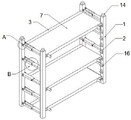
Fig. 1 is a schematic structural view of the present invention;
FIG. 2 is a schematic view of the cross beam structure of the present invention;
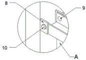
FIG. 3 is an enlarged schematic view of part A of the present invention;
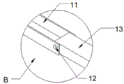
fig. 4 is a schematic view of the folding structure of the present invention;
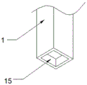
fig. 5 is a schematic view of the bottom structure of the upright post of the present invention.
In the figure: 1. a column; 2. fixing grooves; 3. a cross beam; 4. a movable groove; 5. a movable block; 6. a handle; 7. a partition plate; 8. a fixed block; 9. a hole; 10. a first bolt; 11. a U-shaped groove; 12. a second bolt; 13. a connecting rod; 14. a clamping block; 15. a groove; 16. and fixing the bracket.
Detailed Description
The technical solutions in the embodiments of the present invention will be described clearly and completely with reference to the accompanying drawings in the embodiments of the present invention, and it is obvious that the described embodiments are only some embodiments of the present invention, not all embodiments. Based on the embodiments in the present invention, all other embodiments obtained by a person skilled in the art without creative work belong to the protection scope of the present invention.
Referring to fig. 1-5, the present invention provides a technical solution of stack type rack for logistics storage:
according to shown in fig. 1-5, a stack type skillful rack for logistics storage comprises four upright posts 1, a plurality of fixing grooves 2 are formed in the front faces of the four upright posts 1, a plurality of fixing supports 16 are fixedly arranged at the bottoms of the fixing grooves 2, a plurality of cross beams 3 are connected with the corresponding clamping of the four upright posts 1, a partition plate 7 is connected with the top ends of the cross beams 3 in a clamping mode, movable grooves 4 are formed in the two ends of the cross beams 3, movable blocks 5 are arranged in the two movable grooves 4 in an equal movable mode, and handles 6 are fixedly arranged at one ends of the movable blocks 5.
In addition, the equal fixed mounting in one side of four stands 1 has a plurality of fixed blocks 8, hole 9 has all been seted up at the middle part of a plurality of fixed blocks 8, the equal threaded connection in inside of hole 9 has first bolt 10, the equal movable mounting in outside of first bolt 10 has beta structure, beta structure is by U type groove 11, second bolt 12 and connecting rod 13 are constituteed, connecting rod 13 passes through second bolt 12 and U type groove 11 threaded connection, the other end and the first bolt 10 threaded connection of connecting rod 13, the top fixed mounting of stand 1 has fixture block 14, recess 15 has been seted up to the bottom of stand 1, recess 15 can be connected with fixture block 14 block.
When the stacking type rack is used, the stacking type rack is installed, when the height between the clapboards 7 cannot meet the height of placing objects, the handle 6 is operated to enable the movable block 5 to move in the movable groove 4, the cross beam 3 is moved to the height suitable for the objects, the movable block 5 is inserted into the corresponding fixed groove 2 by the handle 6, the clapboards 7 are clamped and installed at the top end of the cross beam 3, the fixed support 16 at the bottom of the fixed groove 2 supports the cross beam 3, the effect of adjusting the layer height is achieved, the space waste utilization rate of the stacking type rack is solved, the stability of the objects is guaranteed, meanwhile, the hidden danger of falling objects during use is reduced, when the objects do not need to be placed, or the stacking type rack needs to be transported and transferred, the clapboards 7 are firstly detached from the cross beam 3, the two stand columns 1 are operated, make connecting rod 13 fold the inside to U type groove 11 through second bolt 12 for two stands 1 can carry out furthest's folding, folding back ingenious solid frame has reduced occupation space greatly, made things convenient for the storage of ingenious solid frame, also made things convenient for transportation and the transport of ingenious solid frame, the efficiency of work has been increaseed, the time that the work needs has been reduced, stand 1 be equipped with recess 15, recess 15 can be connected with the block 14 on top can the block, piling up of ingenious solid frame has reduced area greatly.
In the description of the present invention, it should be understood that the indicated orientation or positional relationship is based on the orientation or positional relationship shown in the drawings, and is only for convenience of description and simplification of description, and does not indicate or imply that the indicated device or element must have a particular orientation, be constructed and operated in a particular orientation, and thus should not be construed as limiting the present invention.
In the present invention, unless otherwise explicitly specified or limited, for example, it may be fixedly connected, detachably connected, or integrated; can be mechanically or electrically connected; they may be directly connected or indirectly connected through an intermediate medium, and may be connected through the inside of two elements or in an interaction relationship between two elements, unless otherwise specifically defined, and the specific meaning of the above terms in the present invention will be understood by those skilled in the art according to specific situations.
Although embodiments of the present invention have been shown and described, it will be appreciated by those skilled in the art that changes, modifications, substitutions and alterations can be made in these embodiments without departing from the principles and spirit of the invention, the scope of which is defined in the appended claims and their equivalents.
Claims (7)
1. The utility model provides a commodity circulation storage is with ingenious solid frame of heap, includes four stand (1), its characterized in that: four a plurality of fixed slots (2) have all been seted up in the front of stand (1), and are a plurality of the equal fixed mounting in bottom of fixed slot (2) has a plurality of fixed bolster (16), four the corresponding block of stand (1) is connected with a plurality of crossbeams (3), and is a plurality of the equal block in top of crossbeam (3) is connected with baffle (7).
2. The stacked smart rack for logistics storage according to claim 1, wherein: a plurality of movable groove (4), two have all been seted up at the both ends of crossbeam (3) the equal movable mounting in inside in movable groove (4) has movable block (5), two the equal fixed mounting in one end of movable block (5) has handle (6).
3. The stacked smart rack for logistics storage according to claim 1, wherein: four equal fixed mounting in one side of stand (1) has a plurality of fixed blocks (8), and is a plurality of hole (9) have all been seted up at the middle part of fixed block (8).
4. The stacked smart rack for logistics storage according to claim 3, wherein: the hole (9) is internally and uniformly in threaded connection with a first bolt (10), and the outside of the first bolt (10) is movably provided with a folding structure.
5. The stacked smart rack for logistics storage according to claim 4, wherein: the folding structure is composed of a U-shaped groove (11), a second bolt (12) and a connecting rod (13), the connecting rod (13) is in threaded connection with the U-shaped groove (11) through the second bolt (12), and the other end of the connecting rod (13) is in threaded connection with the first bolt (10).
6. The stacked smart rack for logistics storage according to claim 1, wherein: and a clamping block (14) is fixedly mounted at the top end of the upright post (1).
7. The stacked smart rack for logistics storage according to claim 1, wherein: the bottom end of the upright post (1) is provided with a groove (15), and the groove (15) can be clamped and connected with the clamping block (14).
Priority Applications (1)
| Application Number | Priority Date | Filing Date | Title |
|---|---|---|---|
| CN202023072619.3U CN214086113U (en) | 2020-12-19 | 2020-12-19 | Stack type ingenious fixing frame for logistics storage |
Applications Claiming Priority (1)
| Application Number | Priority Date | Filing Date | Title |
|---|---|---|---|
| CN202023072619.3U CN214086113U (en) | 2020-12-19 | 2020-12-19 | Stack type ingenious fixing frame for logistics storage |
Publications (1)
| Publication Number | Publication Date |
|---|---|
| CN214086113U true CN214086113U (en) | 2021-08-31 |
Family
ID=77429399
Family Applications (1)
| Application Number | Title | Priority Date | Filing Date |
|---|---|---|---|
| CN202023072619.3U Active CN214086113U (en) | 2020-12-19 | 2020-12-19 | Stack type ingenious fixing frame for logistics storage |
Country Status (1)
| Country | Link |
|---|---|
| CN (1) | CN214086113U (en) |
-
2020
- 2020-12-19 CN CN202023072619.3U patent/CN214086113U/en active Active
Similar Documents
| Publication | Publication Date | Title |
|---|---|---|
| CN219340561U (en) | Cantilever type stereoscopic warehouse goods shelves | |
| CN210102617U (en) | Cross beam type three-dimensional warehouse shelf | |
| CN217280998U (en) | Storage battery storage rack | |
| CN216995760U (en) | Traction transformer storage and transportation integrated packaging structure | |
| CN215710041U (en) | Hollow glass operation stacking frame | |
| CN214113224U (en) | Foldable ingenious fixing frame | |
| CN218641327U (en) | Assembled tire storage rack | |
| CN212952405U (en) | Fluent strip storage rack | |
| CN210285137U (en) | Subway train brake disc transportation strorage device | |
| CN210794514U (en) | Storage rack for warehouse tubular goods | |
| CN212952390U (en) | A turnover device for electric power warehouse | |
| CN219728863U (en) | Quick-dismantling goods shelf for metal component | |
| CN223703875U (en) | Adjustable freight frame for logistics transportation | |
| CN218617693U (en) | Detachable combined goods storage rack structure | |
| CN218605713U (en) | Modular tray formula goods shelves of dismouting soon | |
| CN218401394U (en) | Perpendicular warehouse for storing drinks | |
| CN217754558U (en) | Novel smart solid frame with classification function | |
| CN210028308U (en) | Four-way fork-feeding foldable cloth rack | |
| CN221050254U (en) | Stacked packaging container | |
| CN213136733U (en) | Angle steel rack | |
| CN214731671U (en) | Heavy storage rack | |
| CN218999971U (en) | Combined multifunctional rack convenient for cargo transportation | |
| CN220430188U (en) | Movable turnover vehicle with adjustable height for biological laboratory | |
| CN217023287U (en) | Novel foldable stack frame | |
| CN213907657U (en) | Cultivation container holding rack |
Legal Events
| Date | Code | Title | Description |
|---|---|---|---|
| GR01 | Patent grant | ||
| GR01 | Patent grant |