CN214081154U - Hardware wrench structure - Google Patents
Hardware wrench structure Download PDFInfo
- Publication number
- CN214081154U CN214081154U CN202022491371.8U CN202022491371U CN214081154U CN 214081154 U CN214081154 U CN 214081154U CN 202022491371 U CN202022491371 U CN 202022491371U CN 214081154 U CN214081154 U CN 214081154U
- Authority
- CN
- China
- Prior art keywords
- handle
- head
- wrench
- connector
- screw rod
- Prior art date
- Legal status (The legal status is an assumption and is not a legal conclusion. Google has not performed a legal analysis and makes no representation as to the accuracy of the status listed.)
- Expired - Fee Related
Links
- 241000282472 Canis lupus familiaris Species 0.000 claims 2
- 241000282693 Cercopithecidae Species 0.000 claims 1
- 230000008859 change Effects 0.000 description 3
- 229910052751 metal Inorganic materials 0.000 description 2
- 239000002184 metal Substances 0.000 description 2
- 150000002739 metals Chemical class 0.000 description 2
- 230000004048 modification Effects 0.000 description 2
- 238000012986 modification Methods 0.000 description 2
- 230000006872 improvement Effects 0.000 description 1
- 238000000034 method Methods 0.000 description 1
- 230000008569 process Effects 0.000 description 1
Images


Landscapes
- Details Of Spanners, Wrenches, And Screw Drivers And Accessories (AREA)
Abstract
The utility model provides a hardware wrench structure, including first spanner head, second adjustable spanner head and connector, first spanner head is installed to one side of connector, install second adjustable spanner head in the first spanner head, second adjustable spanner head one side is the adjustable spanner mouth, the opposite side of second adjustable spanner head is equipped with the screw thread, be equipped with the screw rod in the first spanner head, the one end of screw rod is installed in first spanner head, the other end of screw rod passes first spanner head, and the bottom of screw rod is installed the connecting rod, be equipped with logical groove on the connector, install first handle in the logical groove; the novel multifunctional wrench is characterized in that a second handle is installed in the first handle, a plurality of stop blocks are installed on the second handle, springs are installed at the bottom ends of the stop blocks, dovetail grooves are formed in the second handle, dovetail sliding blocks are installed in the dovetail grooves, and connecting rods are installed on the dovetail sliding blocks.
Description
Technical Field
The utility model belongs to the technical field of hardware and tools, concretely relates to five metals spanner structure.
Background
The wrench is a hand tool for screwing bolts, screws, nuts and other opening or trepanning fasteners for tightly holding the bolts or the nuts through threads by utilizing the lever principle, and usually, the opening or trepanning of the bolts or the nuts can be screwed by clamping the handle part to apply external force to the handle part and applying the external force to one end or two ends of the handle part. When the wrench is used, external force is applied to the handle part along the rotation direction of the threads, so that the bolt or the nut can be screwed, and common centralized wrenches comprise a box wrench, a dual-purpose wrench, an adjustable wrench and the like.
The existing hardware wrench is inconvenient to use, cannot adjust length, is inconvenient to operate, long in time and low in efficiency due to the fact that the wrench needs to be continuously replaced when the wrench is different in shape, and cannot be changed when the wrench is inconvenient to position, and operation difficulty is increased.
SUMMERY OF THE UTILITY MODEL
The utility model aims at solving the problems existing in the prior art, the utility model provides a hardware wrench structure, simple structure, convenient to use is applicable to most occasions.
The utility model provides a following technical scheme:
the utility model provides a five metals spanner structure, includes first spanner head, second adjustable spanner head and connector, first spanner head is installed to one side of connector, install second adjustable spanner head in the first spanner head, second adjustable spanner head one side is the adjustable spanner mouth, the opposite side of second adjustable spanner head is equipped with the screw thread, be equipped with the screw rod in the first spanner head, the one end of screw rod is installed in first spanner head, the other end of screw rod passes first spanner head, just the connecting rod is installed to the bottom of screw rod, be equipped with logical groove on the connector, logical inslot is installed first handle.
Further, a second handle is installed in the first handle, a plurality of stop blocks are installed on the second handle, springs are installed at the bottom ends of the stop blocks, dovetail grooves are formed in the second handle, dovetail sliding blocks are installed in the dovetail grooves, and connecting rods are installed on the dovetail sliding blocks.
Further, the second adjustable wrench head is movably mounted in the first wrench head.
Furthermore, the outer wall of the first handle is provided with a non-slip mat.
Further, the spring installed at the bottom end of the stop block is installed in the head of the second adjustable wrench.
Further, a screw is installed at one end of the connector, the screw penetrates through the connector and the first handle, a knob is installed on the screw, and the knob is installed at the other end of the connector.
Furthermore, a hanging hole is arranged on the second handle.
Furthermore, a through hole is formed in the head of the first wrench, the length of the through hole is smaller than that of the screw rod, and the width of the through hole is larger than that of the screw rod.
The utility model has the advantages that: through the setting of connector, first spanner head and second spanner head can change the angle, are applicable to narrow occasion, install the forked tail slider, when drawing close second spanner head to first spanner head, and is more laborsaving, the operation of being convenient for.
Drawings
The accompanying drawings are included to provide a further understanding of the invention, and are incorporated in and constitute a part of this specification, illustrate embodiments of the invention, and together with the description serve to explain the invention and not to limit the invention. In the drawings:
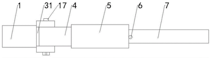
fig. 1 is a schematic front view of the present invention;
fig. 2 is a schematic top view of the present invention.
Fig. 3 is a cross-sectional view of the second handle.
Labeled as: 1. a first wrench head; 2. a through hole; 3. a connector; 31. a through groove; 4. a first handle; 5. a non-slip mat; 6. a stopper; 7. a second handle; 8. hanging holes; 9. a second adjustable wrench head; 91. A movable jaw; 10. a thread; 11. a screw; 12. a knob; 13. a connecting rod; 14. a dovetail block; 15. A spring; 16. a dovetail groove; 17. and (4) screws.
Detailed Description
As shown in fig. 1, 2 and 3, a hardware wrench structure comprises a first wrench head 1, a second adjustable wrench head 9 and a connector 3, the first wrench head 1 is installed on one side of the connector 3, the first wrench head 1 is fixedly installed on the connector 3, the second adjustable wrench head 9 is installed in the first wrench head 1, an adjustable wrench opening 91 is formed on one side of the second adjustable wrench head 9, a thread 10 is arranged on the other side of the second adjustable wrench head 9, a screw 11 is arranged in the first wrench head 1, the screw 11 is fixed by the rotation of the screw 11, the second adjustable wrench head 9 with the thread 10 moves in the first wrench head 1, so as to clamp and loosen a nut, one end of the screw 11 is installed in the first wrench head 1, the screw 11 makes a rotation movement, the other end of the screw 11 passes through the first wrench head 1, and a connecting rod 13 is installed at the bottom end of the screw 11, the connector 3 is provided with a through groove 31, and a first handle 4 is arranged in the through groove 31.
A second handle 7 is arranged in the first handle 4, a plurality of stop blocks 6 are arranged on the second handle 7, springs 15 are arranged at the bottom ends of the stop blocks 6, the length of the whole handle can be adjusted through the stop blocks 6, the stop blocks 6 are pressed, the springs 15 under the stop blocks 6 are compressed and contracted, the second handle 7 moves towards the inside of the first handle 4, the second handle 7 is pulled towards the opposite direction of the first handle 4, the stop blocks 6 are pushed out by the spring force of the springs 15 to prevent the second handle 7 from moving towards the inside of the first handle 4 to be fixed left and right, dovetail grooves 16 are arranged in the second handle 7, dovetail slide blocks 14 are arranged in the dovetail grooves 16, connecting rods 13 are arranged on the dovetail slide blocks 14, the head part 9 of the second adjustable wrench is movably arranged in the head part 1 of the first wrench, the dovetail blocks 14 slide up and down in the dovetail grooves 16, the connecting rods 13 connected with the dovetail blocks 14 move, the connecting rods 13 are arranged at the front end of the screw rod 11, the movement of the connecting rod 13 causes the screw 11 to perform a rotational movement.
Install slipmat 5 on the outer wall of first handle 4, prevent to take place to skid in operation process, improve safe operability, install spring 15 in 6 bottoms of dog in second adjustable spanner head 9, screw 17 is installed to the one end of connector 3, screw 17 passes connector 3 and first handle 4, install knob 12 on the screw 17, and the other end at connector 3 is installed to knob 12, loosen the connection between first handle 4 and the connector 3 through knob 12, can change the angle of connector 3, thereby change the angle of first spanner head 1 and second adjustable spanner head 9, install hanging hole 8 on the second handle 7.
Be equipped with through-hole 2 on the first spanner head 1, the length of through-hole 2 is less than the length of screw rod 11, and the width of through-hole 2 is greater than the width of screw rod 11, is convenient for observe the rotary motion of screw rod 11 and the motion condition of screw thread 10.
When the utility model is used, when the bolt is screwed, the bolt is firstly clamped, the stop block 6 is pressed according to the length of the distance adjusting handle, the second handle 7 moves towards the inside of the first handle 4 to shorten the handle length, the second handle 7 moves towards the opposite direction of the first handle 4, the stop block 6 pops up to block the second handle 7 to move continuously, the handle length is extended, one hand holds the antiskid pad 5 of the first handle 4, the other hand is placed on the dovetail block 14 to make the dovetail block 14 move leftwards along the dovetail groove 16, the connecting rod 13 arranged on the dovetail block 14 pushes the screw rod 11 to rotate, the screw rod 11 is fixed to rotate, the screw thread 10 on the head 9 of the second adjustable wrench is matched with the screw rod, the head 9 of the second adjustable wrench moves towards the head 1 of the first wrench, the bolt is clamped, if the space is narrow and small, when the operation is inconvenient, the rotating knob 12 loosens the connector 3 and the first handle 4, after the angle of, and then the knob 12 is screwed, the bolt is screwed out or in by operating the wrench, if the bolt is loosened, the dovetail block 14 moves rightwards, the connecting rod 13 with the screw 11 moves reversely, and the head 9 of the second adjustable wrench is far away from the head 1 of the first wrench, so that the bolt is loosened.
Although the present invention has been described in detail with reference to the foregoing embodiments, it will be apparent to those skilled in the art that modifications may be made to the embodiments described in the foregoing embodiments, or equivalents may be substituted for elements thereof. Any modification, equivalent replacement, or improvement made within the spirit and principle of the present invention should be included in the protection scope of the present invention.
Claims (7)
1. A hardware wrench structure comprises a first wrench head (1), a second adjustable wrench head (9) and a connector (3), it is characterized in that one side of the connector (3) is provided with a first wrench head (1), a second adjustable wrench head (9) is arranged in the first wrench head (1), one side of the second adjustable wrench head (9) is an adjustable wrench opening (91), the other side of the second adjustable wrench head (9) is provided with a thread (10), a screw rod (11) is arranged in the first wrench head part (1), one end of the screw rod (11) is arranged in the first wrench head part (1), the other end of the screw rod (11) passes through the first wrench head part (1), a connecting rod (13) is installed at the bottom end of the screw rod (11), a through groove (31) is formed in the connecting head (3), and a first handle (4) is installed in the through groove (31);
install second handle (7) in first handle (4), install a plurality of dogs (6) on second handle (7), spring (15) are installed to the bottom of dog (6), be equipped with dovetail (16) in second handle (7), dovetail slider (14) are installed in dovetail (16), install connecting rod (13) on dovetail slider (14).
2. A hardware wrench structure according to claim 1, characterised in that the second spanner head (9) is movably mounted in the first spanner head (1).
3. Structure according to claim 1, characterized in that said first handle (4) has a non-slip pad (5) mounted on its outer wall.
4. A hardware wrench structure according to claim 1, characterised in that the spring (15) mounted at the bottom end of the stop (6) is mounted in the second monkey wrench head (9).
5. The hardware wrench structure according to claim 1, wherein a screw (17) is installed at one end of the connector (3), the screw (17) passes through the connector (3) and the first handle (4), a knob (12) is installed on the screw (17), and the knob (12) is installed at the other end of the connector (3).
6. The hardware wrench structure according to claim 1, wherein the second handle (7) is provided with a hanging hole (8).
7. The hardware wrench structure according to claim 1, wherein the first wrench head (1) is provided with a through hole (2), the length of the through hole (2) is smaller than that of the screw rod (11), and the width of the through hole (2) is greater than that of the screw rod (11).
Priority Applications (1)
| Application Number | Priority Date | Filing Date | Title |
|---|---|---|---|
| CN202022491371.8U CN214081154U (en) | 2020-11-02 | 2020-11-02 | Hardware wrench structure |
Applications Claiming Priority (1)
| Application Number | Priority Date | Filing Date | Title |
|---|---|---|---|
| CN202022491371.8U CN214081154U (en) | 2020-11-02 | 2020-11-02 | Hardware wrench structure |
Publications (1)
| Publication Number | Publication Date |
|---|---|
| CN214081154U true CN214081154U (en) | 2021-08-31 |
Family
ID=77447433
Family Applications (1)
| Application Number | Title | Priority Date | Filing Date |
|---|---|---|---|
| CN202022491371.8U Expired - Fee Related CN214081154U (en) | 2020-11-02 | 2020-11-02 | Hardware wrench structure |
Country Status (1)
| Country | Link |
|---|---|
| CN (1) | CN214081154U (en) |
-
2020
- 2020-11-02 CN CN202022491371.8U patent/CN214081154U/en not_active Expired - Fee Related
Similar Documents
| Publication | Publication Date | Title |
|---|---|---|
| CN205184651U (en) | Pincers of pulling pin | |
| CN220807134U (en) | Adjustable wrench with external hexagonal function | |
| CN218905158U (en) | Novel T-shaped wrench capable of screwing bolts with multiple specifications | |
| CN221270985U (en) | Adjustable spanner | |
| CN110732992A (en) | solid head type adjustable wrench | |
| CN215847876U (en) | Convenient wrench | |
| CN221232446U (en) | Spanner with adjustable handle | |
| CN219925894U (en) | Multipurpose wrench for power construction | |
| CN223326269U (en) | Screw wrench | |
| CN221474980U (en) | Automatic tightening wrench | |
| CN219404083U (en) | A kind of multi-functional movable tightening wrench | |
| CN220162318U (en) | Screw wrench | |
| CN218947507U (en) | Multifunctional double-ended wrench | |
| CN210939002U (en) | Dull head type adjustable wrench | |
| CN217703188U (en) | Telescopic socket wrench | |
| CN221622057U (en) | Driving type hydraulic wrench | |
| CN222038359U (en) | Torque spanner | |
| CN220007601U (en) | Spanner with anti-slip function | |
| CN221291144U (en) | Swivel nut installation frock | |
| CN220030035U (en) | Adjustable wrench capable of fixing opening | |
| CN220592972U (en) | Novel spanner instrument convenient to assembly debugging is used | |
| CN212330843U (en) | An emergency portable multifunctional live wrench | |
| CN220007615U (en) | Plane angle adjustable combined adjustable spanner | |
| CN204565989U (en) | A kind of power transmission lines overhauling spanner | |
| CN210025077U (en) | Multifunctional ratchet bathroom wrench |
Legal Events
| Date | Code | Title | Description |
|---|---|---|---|
| GR01 | Patent grant | ||
| GR01 | Patent grant | ||
| CF01 | Termination of patent right due to non-payment of annual fee | ||
| CF01 | Termination of patent right due to non-payment of annual fee |
Granted publication date: 20210831 |