SUMMERY OF THE UTILITY MODEL
The utility model provides a multinuclear element enrichment facility in marine environment realizes the automatic reloading of radioactive element collection device to the problem that the radioactive element collection efficiency is low that the manual work leads to of reloading has been avoided.
In order to achieve the above object, the utility model provides a following technical scheme:
a device for enriching multi-core in marine environment comprises a box body and a control box arranged on the box body and used for storing a power supply and a control module, wherein a storage box used for storing light materials is arranged at one end of the box body close to the sea level and positioned in the box body; a feeding linear module for storing the standby nuclide collecting barrel is arranged on any inner wall of the box body vertical to the sea level, and a receiving linear module is arranged on the inner wall of the box body parallel to the feeding linear module; when the feeding linear module moves linearly, the standby nuclide collecting barrel arranged on the feeding linear module can be in rigid contact with the nuclide collecting barrel on the lifting mechanism, so that the nuclide collecting barrel on the lifting mechanism can move along with the movement of the standby nuclide collecting barrel, the nuclide collecting barrel is separated from the lifting mechanism, and can be matched with the receiving linear module after being separated and move along with the driving of the receiving linear module.
Preferably, the lifting mechanism adopts a motor to drive a winding drum, the winding drum is installed between the two mounting plates through a bearing, a rope is wound on the winding drum, one end of the rope is fixed on the winding drum, the other end of the rope penetrates through the wall of the box body and is fixed on a lifting lug of the floating plate, a sliding table is fixedly installed at one end of the floating plate close to the sea level, a sliding groove is correspondingly installed at one end of the nuclide collecting barrel far away from the sea level, and the sliding groove on the nuclide collecting barrel is matched with the sliding table on the floating plate to be installed, so that the nuclide collecting barrel can move along the length direction of the sliding table; install two slip tables on the lateral wall of nuclide collecting vessel, 180 degrees in the interval on the circumference of nuclide collecting vessel between two slip tables, correspond it respectively installs a spout to divide equally on the slip table of pay-off sharp module and connecing material sharp module for spout on pay-off sharp module and connecing the material sharp module can cooperate with two slip tables of nuclide collecting vessel lateral wall respectively when being linear motion.
Further, the floating plate is provided with a limiting device used for limiting the nuclide collecting barrel to do linear motion along the length direction of the floating plate sliding table, and the limiting device is also arranged on the chute arranged on the feeding linear module and the receiving linear module sliding table and used for preventing the nuclide collecting barrel from falling off from the chute when moving along with the receiving linear module or the feeding linear module.
And furthermore, the two ends of the box body are provided with the weight boxes, and the weights of the two sides of the box body can be adjusted through the weight boxes to be consistent.
Still further, the ball or roller is all installed to the spout bottom that installs on nuclide collecting vessel, the sharp module of connecing material and the sharp module of pay-off, reduces the friction between spout and the slip table.
Compared with the prior art, the beneficial effects of the utility model are that: the utility model discloses a at pay-off sharp module with connect the rope hoist and mount nuclide collecting vessel on the cylinder between the material straight line module, through pay-off sharp module with connect the operation of material straight line module, realized automatic reloading to effectual artifical reloading of having avoided, the problem that the nuclide collection efficiency that causes is low.
Detailed Description
The technical solutions in the embodiments of the present invention will be described clearly and completely with reference to the accompanying drawings in the embodiments of the present invention, and it is obvious that the described embodiments are only some embodiments of the present invention, not all embodiments. Based on the embodiments in the present invention, all other embodiments obtained by a person skilled in the art without creative work belong to the protection scope of the present invention.
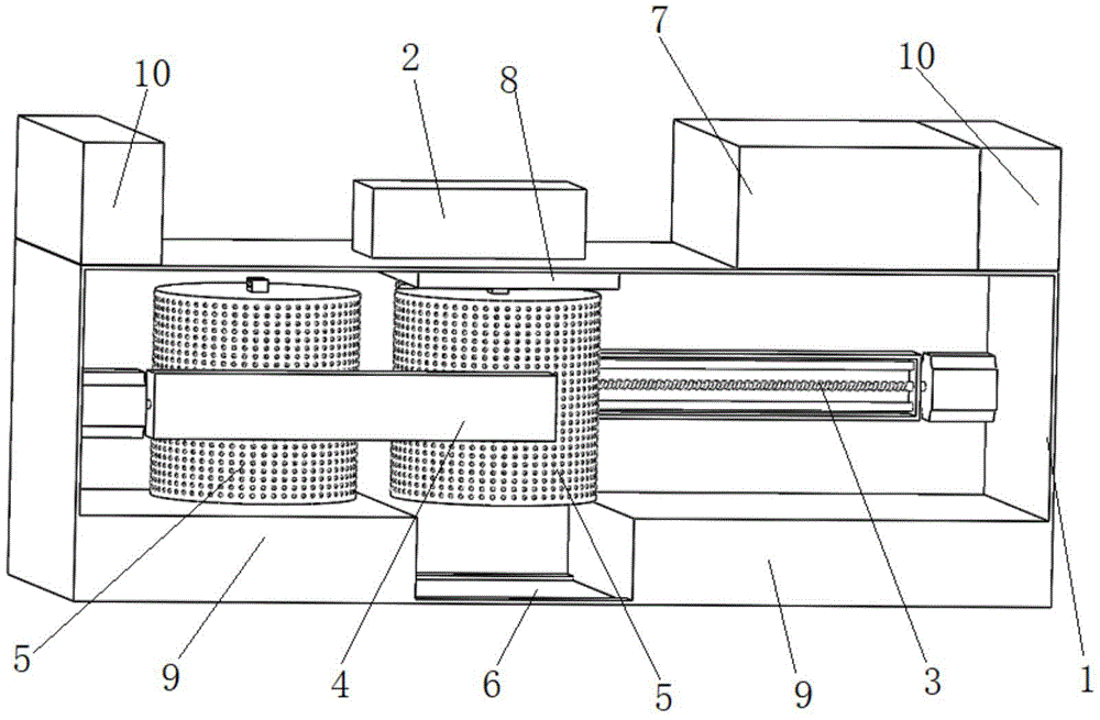
As shown in fig. 1 to 6, a device for enriching a polynucleotide in an ocean environment comprises a box body 1 and a control box 7 arranged on the box body 1 and used for storing a power supply and a control module, wherein the box body 1 is arranged at one end close to the sea level and is provided with a storage box 9 used for storing a light material, the end of the box body 1 far away from the sea level is provided with a lifting mechanism 2 capable of driving a nuclide collecting barrel 5 used for adsorbing nuclides to move vertically upwards or vertically downwards based on the sea level, and an opening 6 for the nuclide collecting barrel 5 to pass through is correspondingly arranged on the wall of the box body 1 close to the sea level; a feeding linear module 4 for storing a standby nuclide collecting barrel 5 is arranged on any inner wall of the box body 1 perpendicular to the sea level, and a receiving linear module 3 is arranged on the inner wall of the box body 1 parallel to the feeding linear module 4; when the feeding linear module 4 moves linearly, the standby nuclide collecting barrel 5 arranged on the feeding linear module can be in rigid contact with the nuclide collecting barrel 5 on the lifting mechanism 2, so that the nuclide collecting barrel 5 on the lifting mechanism 2 can move along with the movement of the standby nuclide collecting barrel 5, the nuclide collecting barrel 5 is separated from the lifting mechanism 2, and can be matched with the receiving linear module 3 after being separated and move along with the driving of the receiving linear module 3.
Preferably, the lifting mechanism 2 adopts a motor 15 to drive a winding drum 17, the winding drum 17 is installed between two installation plates 16 through a bearing, a rope 14 is wound on the winding drum 17, one end of the rope 14 is fixed on the winding drum 17, the other end of the rope passes through the wall of the box body 1 and is fixed on a lifting lug 13 of the floating plate 8, one end of the floating plate 8 close to the sea level is fixedly provided with a sliding table 12, a sliding chute 11 is correspondingly installed at one end of the nuclide collection barrel 5 far away from the sea level, the sliding chute 11 on the nuclide collection barrel 5 is installed in a matching way with the sliding table 12 on the floating plate 8, so that the nuclide collection barrel 5 can move along the length direction of the sliding table 12; install two slip tables 12 on the lateral wall of nuclide collecting vessel 5, separate 180 degrees on the circumference of nuclide collecting vessel 5 between two slip tables 12, what correspond is in it respectively installs a spout 11 to divide equally on the slip table of pay-off sharp module 4 and material receiving sharp module 3 for spout 11 on pay-off sharp module 4 and the material receiving sharp module 3 can cooperate with two slip tables 12 of nuclide collecting vessel 5 lateral wall respectively when being linear motion.
Further, the floating plate 8 is provided with a limiting device for limiting the nuclide collecting barrel 5 to do linear motion along the length direction of the sliding table 12 of the floating plate 8, the feeding linear module 4 and the sliding table of the receiving linear module 3 are provided with the limiting device on the sliding groove 11, and the limiting device is used for preventing the nuclide collecting barrel 5 from falling off from the sliding groove 11 when moving along with the receiving linear module 3 or the feeding linear module 4.
Furthermore, the weight boxes 10 are arranged at the two ends of the box body 1, and the weights at the two sides of the box body 1 can be adjusted through the weight boxes 10 to be consistent.
Still further, balls or rollers 18 are arranged at the bottoms of the chutes 11 arranged on the nuclide collecting barrel 5, the material receiving linear module 3 and the material feeding linear module 4, so that the friction between the chutes 11 and the sliding table 12 is reduced.
Referring to fig. 7 and 8, the limiting devices installed on the floating plate 8 and the chutes 11 of the feeding linear module 4 and the receiving linear module 3 respectively comprise an electric push rod 21, a push plate 20 is installed on the head of the electric push rod 21, and two ends of the push plate 20 are respectively provided with a limiting rod 19; the limiting rods 19 of the limiting device arranged on the floating plate 8 are respectively positioned at two ends of the length direction of the sliding table 12 of the floating plate 8 and movably penetrate through the floating plate 8, the distance between the two limiting rods 19 is slightly larger than the length of the sliding chute 11 arranged on the nuclide collecting barrel 5, and the sliding chute 11 on the nuclide collecting barrel 5 is positioned between the two limiting rods 19 during limiting, so that the nuclide collecting barrel 5 is effectively prevented from moving along the length direction of the sliding table 12 on the floating plate 8; pay-off sharp module 4 and connect the stop lever 19 of the stop device on the material sharp module 3 all to be located 11 length direction's of spout both ends and mobilizable 11 inner walls of spout that run through, and the distance between two stop levers 19 slightly is greater than the slip table 12 length of installation on the nuclide collecting vessel 5, makes when spacing, the slip table 12 on the nuclide collecting vessel 5 can be located between two stop levers 19, thereby effectually prevented nuclide collecting vessel 5 when moving along with pay-off sharp module 4 or connect material sharp module 3, drop from pay-off sharp module 4 or connect material sharp module 3. Its stop device is not limited to adopting above-mentioned stop device, and stop device's aim at restriction slip table 12 moves or spout 11 moves along the length direction of slip table 12 along the length direction of spout 11, consequently can play the stop device of above-mentioned effect all can use in known stop device the utility model discloses in.
Referring to the attached figure 9, only a spare nuclide collecting barrel 5 needs to be placed on the feeding linear module 4 through the utility model, when the spare nuclide collecting barrel 5 is placed, the sliding table 12 on the side wall of the spare nuclide collecting barrel 5 is assembled with the sliding chute 11 installed on the feeding linear module 4, referring to the attached figure 2, when nuclide is collected, the nuclide collecting barrel 5 is placed under the sea by controlling the rotation of the winding drum 17 through the motor 15, the floating plate 8 is positioned on the sea surface, the working time of a nuclide collecting box is preset in the control module, when the actual working time of a nuclide collecting box is equal to the preset working time, the winding drum 17 is driven to move through the control module 15, so that the nuclide collecting barrel 5 moves upwards based on the sea level, finally, the floating plate 8 is tightly attached to the inside the top wall of the box body 1 as shown in the attached figure 1, referring to the feeding linear module 4 started in the attached figure 10, the standby nuclide collecting barrel 5 moves linearly in the direction of the nuclide collecting barrel 5 hung on the floating plate 8, so that the standby nuclide collecting barrel 5 is in rigid contact with the nuclide collecting barrel 5 hung on the floating plate 8, the nuclide collecting barrel 5 on the floating plate 8 is pushed to move linearly in the length direction of a sliding table 12 on the floating plate 8, when a sliding groove 11 in the top wall of the nuclide collecting barrel 5 on the floating plate 8 is separated from the sliding table 12 on the floating plate 8, the situation is the situation shown in the attached drawing 10, the sliding table 12 corresponding to the sliding groove 11 on the material receiving linear module 3 and arranged on the side wall of the nuclide collecting barrel 5 are matched with each other, the material receiving linear module 3 is driven to move linearly while being matched, and the standby nuclide collecting barrel 5 is far away from the linear motion; when nuclide collecting vessel 5 breaks away from floating board 8 completely, be the state shown in figure 11 promptly, when nuclide collecting vessel 5's circumference was located floating board 8 completely outside, reserve nuclide collecting vessel 5 reached and floats board 8 under, at this moment at drive pay-off straight line module 4 reverse motion for spout 11 on the pay-off straight line module 4 breaks away from with slip table 12 on the reserve nuclide collecting vessel 5, rethread motor 15 drive reel 17 moves, puts reserve nuclide collecting vessel 5 to continuing to carry out nuclide collection undersea.
When the limiting device shown in fig. 7 and fig. 8 is adopted, a triggering condition is needed in the control system, and the triggering condition can be triggered by installing a limiting switch at a corresponding position, namely installing the limiting switch at the top of the box body 1, at corresponding positions on the sliding table 12 of the floating plate 8, the sliding chute 11 of the material receiving linear module 3 and the sliding chute 11 of the feeding linear module 4; for the sake of clarity and detail of the control principle, the following definitions are made:
a limit switch at the top of the box body 1 is called a limit switch a, and a limit device on the floating plate 8 is called a limit device a;
a limit switch on the sliding groove 11 of the feeding linear module 4 is called a limit switch b, and a limit device arranged on the sliding groove 11 of the feeding linear module 4 is called a limit device b;
a limit switch on the chute 11 of the material receiving linear module 3 is called a limit switch c, and a limit device on the chute 11 of the material receiving linear module 3 is called a limit device c;
the limit switch on the sliding table 12 of the floating plate 8 is called a limit switch d;
hereinafter, the operation of the limiting device a or the operation of the limiting device b or the operation of the limiting device c means that the sliding chute 11 is limited to move along the length direction of the sliding chute 12 or the sliding chute 12 is limited to move along the length direction of the sliding chute 11.
In the initial state, namely when a worker places the device on the sea, the material changing time is set, the device is started, the nuclide collecting barrel 5 is placed into the sea by the lifting mechanism 2 to be collected, only the limit switch b and the limit switch d are triggered, and the limit device b and the limit device a work; when the preset reloading time is reached, the lifting mechanism 2 lifts the nuclide collecting barrel 5 to enable the floating plate 8 to be tightly attached to the top wall of the box body 1, the limit switch a, the limit switch b and the limit switch d are triggered at the moment, the limit device b works, the limit device a is in a working state, the feeding linear module 4 moves at the moment, the standby nuclide collecting barrel 5 pushes the nuclide collecting barrel 5 on the floating plate 8 to move until the sliding table 12 on the nuclide collecting barrel 5 on the floating plate 8 is matched with the sliding groove 11 of the receiving linear module 3, the limit switch a, the limit switch b and the limit switch c are triggered at the moment, and the limit device b and the limit device c work; at the moment, the material receiving linear module 3 transports the replaced nuclide collecting barrel 5 to one end far away from the standby nuclide collecting barrel 5, and meanwhile, the material feeding linear module 4 continuously moves until the limit switch a, the limit switch b, the limit switch c and the limit switch d are all triggered, and the limit device a and the limit device c work; at the moment, the stop device b is released from working state, the standby nuclide collecting barrel 5 is limited on the floating plate 8 at the moment, the feeding linear module 4 moves in reverse direction until the chute 11 on the feeding linear module 4 moves to one end far away from the standby nuclide collecting barrel 5, the lifting mechanism 2 is started to lower the standby nuclide collecting barrel 5 into the sea, the limit switch c and the limit switch d are triggered at the moment, the stop device c and the stop device a work, and the automatic replacement of the nuclide collecting barrel 5 is completed through the control principle.
Preferably, the sliding table 12 is a T-shaped sliding table 12, and the chute 11 is a T-shaped chute 11.
The utility model discloses a guarantee whole device's operation precision, the event pay-off sharp module 4 all adopts the lead screw sharp module with connecing material sharp module 3.
Through the utility model discloses an automatic reloading of nuclide collecting vessel 5, among the present known technical scheme, all not set up reserve nuclide collecting vessel 5, and realize automatic reloading, and nuclide collecting vessel 5 is all put in at marine fixed point, be used for adsorbing nuclide, if nuclide collecting vessel 5 is put in a large number, if when needs are changed, then need pass through artifical collection one by one, during this period, the adsorption efficiency of the nuclide collecting vessel 5 of not changing can reduce gradually, and pass through the utility model discloses regularly realize automatic change, thereby provide abundant time for artifical change used nuclide collecting vessel 5, and in the time quantum through artifical change used nuclide collecting vessel 5, can fully guarantee to nuclide collection efficiency, promptly for present known technical scheme the utility model discloses nuclide collection efficiency has been improved greatly.
It is obvious to a person skilled in the art that the invention is not restricted to details of the above-described exemplary embodiments, but that it can be implemented in other specific forms without departing from the spirit or essential characteristics of the invention. The present embodiments are therefore to be considered in all respects as illustrative and not restrictive, the scope of the invention being indicated by the appended claims rather than by the foregoing description, and all changes which come within the meaning and range of equivalency of the claims are therefore intended to be embraced therein. Any reference sign in a claim should not be construed as limiting the claim concerned.
Furthermore, it should be understood that although the present description refers to embodiments, not every embodiment may contain only a single embodiment, and such description is for clarity only, and those skilled in the art should integrate the description, and the embodiments may be combined as appropriate to form other embodiments understood by those skilled in the art.