Box combination assembled removes public latrine
Technical Field
The utility model belongs to the technical field of the public latrine, concretely relates to box combination assembled removes public latrine.
Background
In large outdoor activities of short duration, such as: the mobile toilet is a problem to be solved if the toilet is used in places such as the start of various projects, foundation color cutting activities, various sports activities with more people streams, various decoration construction sites, outdoor shooting theater groups, scenic spots, temporary office places and the like, and the practical and attractive mobile toilet becomes an indispensable supporting facility.
However, the existing mobile public toilet is inconvenient to transport, the mobile public toilet is slow in moving through a self transportation system, a vehicle is used for moving the mobile public toilet, the occupied space is large, the transportation cost of a large vehicle is high, the public toilet which can be rapidly assembled on site is needed, and the assembled mobile public toilet with the assembled box body is provided for meeting the social requirements.
SUMMERY OF THE UTILITY MODEL
An object of the utility model is to provide a box combination assembled removes public latrine, it is inconvenient to aim at solving the removal public latrine transportation among the prior art, removes comparatively slowly through the transportation system of self, uses the vehicle to remove and removes the public latrine, then occupation space is more, uses the oversize vehicle cost of transportation higher, so need the problem of the public latrine that can on-the-spot fast assembly.
In order to achieve the above object, the utility model provides a following technical scheme: the improved multifunctional electric heating plate comprises a base plate, the riser is inserted all around on the bottom plate top, and four groups swing joint has the roof between the top of riser, the lateral wall of riser evenly is provided with mounting groove and fixing device respectively, fixing device is including fixed pipe, the inner chamber swing joint of fixed pipe has the protecgulum, the rear end fixedly connected with connecting rod of protecgulum, the other end fixedly connected with elasticity of connecting rod presss from both sides, the equal fixedly connected with fixed block in the left and right sides of elasticity clamp, the body of front side riser articulates there is the chamber door.
In order to make, as the utility model relates to an optimal scheme, the top of riser is seted up flutedly, the roof is located the inside of four group's riser top recesses.
In order to make, as the utility model relates to an optimal scheme, the four corners of bottom plate is all pegged graft and is had clamping screw, clamping screw's outer wall spiro union has the nut, the nut is located the bottom of bottom plate.
In order to make, as the utility model relates to an optimal scheme, the inner chamber fixed mounting of fixed pipe has the effect piece, the through-hole has been seted up to the effect piece, the front end that the elasticity pressed from both sides runs through the through-hole and is connected with the connecting rod.
In order to make, as a preferred scheme of the utility model discloses, the inside looks of elasticity clamp side fixedly connected with spring.
In order to make, as a preferred scheme of the utility model, the front end fixedly connected with handle of protecgulum.
In order to make, as the utility model discloses an optimal scheme, the bottom fixedly connected with base of clamping screw.
Compared with the prior art, the beneficial effects of the utility model are that:
1. the vertical plates are fixed conveniently by arranging the fixing device, meanwhile, the vertical plates are convenient to install by workers, and meanwhile, when the device is disassembled, the device can be disassembled quickly, so that the purposes of quick installation and quick disassembly are achieved;
2. the bottom plate can be fixed by arranging the fixing screw rod and the nut, the height of the bottom plate is raised, the fixing screw rod is prevented from damaging the ground by arranging the base, and the fixing screw rod is prevented from being damaged by the ground;
3. through the arrangement of the spring, when the elastic force of the elastic clamp is insufficient, the spring provides elastic force for the fixed block, so that the fixed block can be continuously fixed.
Drawings
The accompanying drawings are included to provide a further understanding of the invention, and are incorporated in and constitute a part of this specification, illustrate embodiments of the invention, and together with the description serve to explain the invention and not to limit the invention. In the drawings:
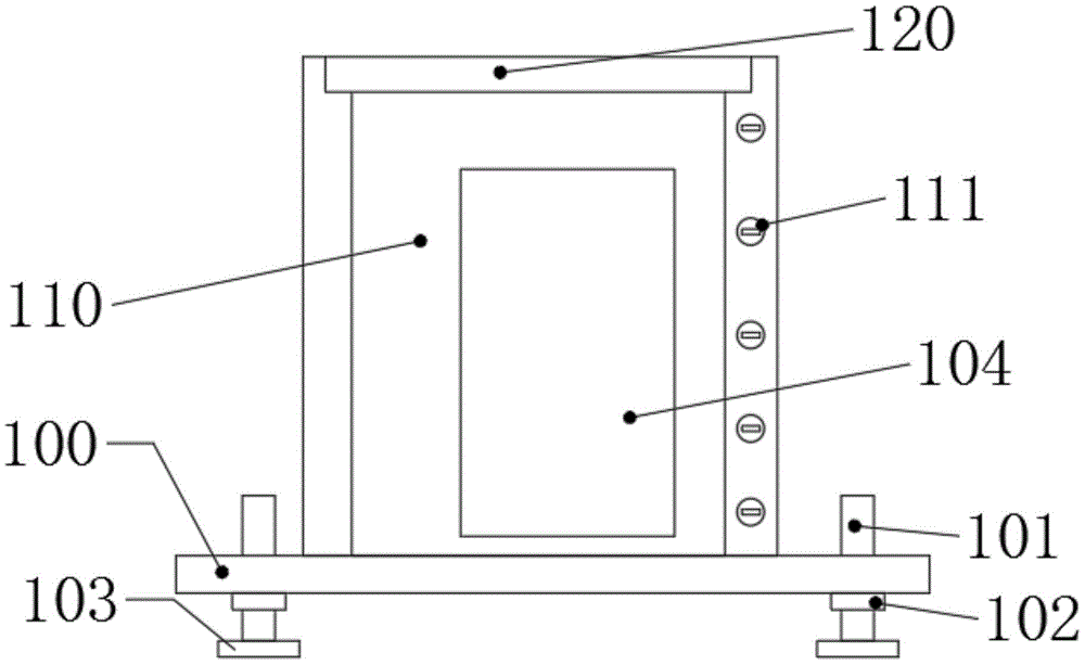
fig. 1 is a schematic structural view of the present invention;
fig. 2 is a schematic view of a vertical plate structure in the present invention;
FIG. 3 is a schematic view of the structure of the fixing tube of the present invention;
fig. 4 is a schematic view of the bottom plate structure of the present invention.
In the figure: 100. a base plate; 101. fixing the screw rod; 102. a nut; 103. a base; 104. a box door; 110. a vertical plate; 111. a fixing device; 112. a fixed tube; 113. a front cover; 114. a connecting rod; 115. an elastic clip; 116. a fixed block; 117. a spring; 118. an action block; 119. a handle; 120. a top plate.
Detailed Description
The technical solutions in the embodiments of the present invention will be described clearly and completely with reference to the accompanying drawings in the embodiments of the present invention, and it is obvious that the described embodiments are only some embodiments of the present invention, not all embodiments. Based on the embodiments in the present invention, all other embodiments obtained by a person skilled in the art without creative work belong to the protection scope of the present invention.
Example 1
Referring to fig. 1-4, the present invention provides the following technical solutions: including bottom plate 100, riser 110 has all been pegged graft all around on bottom plate 100 top, swing joint has roof 120 between four riser 110's of group top, riser 110's lateral wall evenly is provided with mounting groove and fixing device 111 respectively, fixing device 111 includes fixed pipe 112, the inner chamber swing joint of fixed pipe 112 has protecgulum 113, the rear end fixedly connected with connecting rod 114 of protecgulum 113, the other end fixedly connected with elasticity of connecting rod 114 presss from both sides 115, the equal fixedly connected with fixed block 116 in the left and right sides of elasticity clamp 115, the body of front side riser 110 articulates there is chamber door 104.
In the embodiment of the present invention, the fixing screw 101 is inserted into four corners of the bottom plate 100, the bottom plate 100 is driven to move upwards by rotating the nut 102, the fixing screw 101 is fixed, the four sets of the risers 110 are inserted into the mounting groove formed in the left side of the bottom plate 100, the fixing device 111 is inserted into the mounting groove formed in the left side of the bottom plate 100, the fixing block 116 is extended out of the fixing tube 112 by the elastic clamp 115 and the spring 117, the four sets of the risers 110 are fixed by the fixing block 116 being clamped into the mounting groove formed in the left side of the bottom plate 100, the top plate 120 is placed on the top of the riser 110, the top plate 120 is fixed by the groove formed in the top of the riser 110, when disassembly is required, the worker pulls the handle 119 after removing the top plate 120, the worker drives the front cover 113 to move forwards by the handle 119, drives the connecting rod 114 to move forwards by the front cover 113, drives the elastic clamp 115 to move forwards by the connecting rod 114, the elastic clamp 115 moves forwards to drive the fixing block 116 to be separated from the mounting groove formed on the left side of the bottom plate 100, so that the vertical plate 110 is detached.
Specifically, referring to fig. 2, the top of the riser 110 is provided with a groove, and the top plate 120 is located inside the grooves at the tops of the four sets of risers 110.
In the embodiment of the utility model, through being provided with the recess, be convenient for to the fixed of roof 120, through the support of riser 110 to roof 120, be convenient for to the installation of roof 120.
Specifically, referring to fig. 1, fixing screws 101 are inserted into four corners of a bottom plate 100, nuts 102 are screwed on outer walls of the fixing screws 101, and the nuts 102 are located at the bottom of the bottom plate 100.
In the embodiment of the present invention, the bottom plate 100 can be fixed by setting the fixing screw 101 and the nut 102, and the height of the bottom plate 100 is raised.
Specifically, referring to fig. 3, an action block 118 is fixedly installed in the inner cavity of the fixing tube 112, the action block 118 is provided with a through hole, and the front end of the elastic clamp 115 penetrates through the through hole and is connected with the connecting rod 114.
The utility model discloses an in the concrete embodiment, through setting up effect piece 118, prevent that spring 117 and elasticity from pressing from both sides 115 when withdrawing, dead phenomenon of card appears in spring 117 and elasticity clamp 115, effect piece 118 plays limiting displacement, and the elasticity of being convenient for presss from both sides 115 and replies smoothly.
Specifically, referring to fig. 3, a spring 117 is fixedly connected to the viewing side inside the elastic clip 115.
In the embodiment of the present invention, by providing the spring 117, when the elastic force of the elastic clamp 115 is insufficient, the spring 117 provides the elastic force to the fixing block 116, so that the fixing block 116 can continue to fix the vertical plate 110.
Specifically, referring to fig. 3, a handle 119 is fixedly connected to the front end of the front cover 113.
In the embodiment of the present invention, the front cover 113 can be easily pulled out by the handle 119, which is convenient for the worker to use.
Specifically, referring to fig. 1, a bottom end of the fixing screw 101 is fixedly connected to a base 103.
In the embodiment of the utility model, through setting up base 103, prevent that set screw 101 from damaging ground, prevent simultaneously that set screw 101 from receiving the damage because of ground.
Finally, it should be noted that: although the present invention has been described in detail with reference to the foregoing embodiments, it will be apparent to those skilled in the art that modifications may be made to the embodiments described in the foregoing embodiments, or equivalents may be substituted for elements thereof. Any modification, equivalent replacement, or improvement made within the spirit and principle of the present invention should be included in the protection scope of the present invention.