CN214025006U - Automotive interior board frock of polishing - Google Patents
Automotive interior board frock of polishing Download PDFInfo
- Publication number
- CN214025006U CN214025006U CN202022994120.1U CN202022994120U CN214025006U CN 214025006 U CN214025006 U CN 214025006U CN 202022994120 U CN202022994120 U CN 202022994120U CN 214025006 U CN214025006 U CN 214025006U
- Authority
- CN
- China
- Prior art keywords
- polishing
- rod
- threaded
- motor
- connecting rod
- Prior art date
- Legal status (The legal status is an assumption and is not a legal conclusion. Google has not performed a legal analysis and makes no representation as to the accuracy of the status listed.)
- Active
Links
Images
Abstract
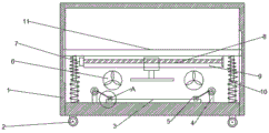
The utility model discloses a car interior plaque frock of polishing, including the storehouse of polishing, the bottom is installed and is placed the platform in the storehouse of polishing, place a both sides and install clamping device, it is fixed tightly to press from both sides the required article of polishing through clamping device, installs the exhaust fan on the back lateral wall in the storehouse of polishing, the exhaust fan will polish the dust suction and filter by the filter screen to play dustproof effect, can highly adjust the upper and lower of mill through elevating gear, improve the efficiency of work, remove through first threaded rod drive threaded block and control and can make the polisher realize controlling, polish the storehouse bottom and still install a plurality of universal wheels, conveniently polish the removal in storehouse, improve the convenience of the frock of polishing.
Description
Technical Field
The utility model relates to a frock of polishing specifically is a frock of polishing of automotive interior plaque.
Background
When an inner decoration plate product is processed, in order to process the inner decoration plate into a specific shape, the surface of the inner decoration plate needs to be polished to be round and smooth, so that a specific handicraft is formed, the inner decoration plate is polished by using a polishing tool, manual work is replaced, and a good polishing effect is achieved;
and traditional grinding device only has single centre gripping fixed function, can't realize carrying out the regulation of position to the polisher, can't adjust the height of polisher, for this reason, we need design a multi-functional frock of polishing.
SUMMERY OF THE UTILITY MODEL
An object of the utility model is to provide an automotive interior board frock of polishing to solve the problem that proposes among the above-mentioned background art.
In order to achieve the above object, the utility model provides a following technical scheme:
a polishing tool for an automotive trim panel comprises a polishing bin, wherein a placing table is installed at the bottom in the polishing bin, clamping devices are installed on two sides of the placing table, a transverse plate is installed in the polishing bin in a sliding mode, a fixing box is installed at the bottom end of the transverse plate, a second motor is installed on the outer side wall of the fixing box, the output end of the second motor penetrates through one side of the fixing box and is connected with a first threaded rod, one end, away from the second motor, of the first threaded rod is rotatably connected to one side of the fixing box through a first bearing, a threaded block is sleeved on the first threaded rod and is in threaded connection with the first threaded rod, a polishing machine is fixedly connected to the bottom of the threaded block, a lifting device is installed at the upper end of the transverse plate and comprises a third motor, a threaded sleeve is fixedly connected to the output end of the third motor, and a second threaded rod is connected in the threaded sleeve, the second threaded rod is in threaded connection with the threaded sleeve, the bottom end of the second threaded rod is fixedly connected with a transverse rod, two limiting blocks are fixedly connected with two ends of the transverse rod, two first sliding blocks are symmetrically sleeved on the transverse rod, guide holes are formed in the first sliding blocks, the first sliding blocks are connected with one ends of the second connecting rods in an articulated mode, the other ends of the second connecting rods are connected with the fixed blocks in an articulated mode, the fixed blocks are further connected with one ends of third connecting rods in an articulated mode, the other ends of the third connecting rods are connected with the second sliding blocks in an articulated mode, the second sliding blocks are connected with transverse plates in a sliding mode, second sliding grooves for sliding of the second sliding blocks are formed in the upper ends of the transverse plates, second sliding rails for sliding of pulleys are formed in the third connecting rods, the pulleys are connected with moving rods, and one ends of the moving.
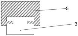
As a further aspect of the present invention: clamping device is including the bracing piece, bracing piece top fixed mounting has first motor, first motor output fixed mounting has the disc, the disc is eccentric articulated with the head rod, the other end of head rod is connected with the grip block, the grip block with place a sliding connection, the first slide rail that supplies the grip block gliding is seted up to the grip block bottom, press from both sides tight fixedly with the required article of polishing through clamping device.
As a further aspect of the present invention: install the exhaust fan on the back lateral wall in storehouse of polishing, the exhaust fan will polish the dust suction and filter by the filter screen to play dustproof effect, effectual reduction dust pollution.
As a further aspect of the present invention: a plurality of universal wheels are further installed at the bottom of the polishing bin, so that the polishing bin can be conveniently moved, and convenience of the polishing tool is improved.
As a further aspect of the present invention: the telescopic rods are installed on two sides of the bottom of the transverse plate, springs are sleeved outside the telescopic rods, one ends of the springs are connected with the bottom end of the transverse plate, the other ends of the springs are connected with the bottom of the polishing bin, and the speed of the transverse plate moving downwards can be reduced.
Compared with the prior art, the beneficial effects of the utility model are that:
1. and clamping and fixing the object to be polished by the clamping device.
2. A plurality of universal wheels are further installed at the bottom of the polishing bin, so that the polishing bin can be conveniently moved, and convenience of the polishing tool is improved.
3. The vertical height of the grinding machine can be adjusted through the lifting device, and the working efficiency is improved.
4. The grinding machine can move left and right by driving the thread block to move left and right through the first threaded rod.
Drawings
Fig. 1 is a schematic structural diagram of a first embodiment of the present invention.
Fig. 2 is a side view of a first embodiment of the present invention.
Fig. 3 is a schematic structural diagram of a second embodiment of the present invention.
In the figure: 1-grinding bin, 2-universal wheel, 3-placing table, 4-supporting rod, 5-clamping block, 6-exhaust fan, 7-second motor, 8-first threaded rod, 9-fixing box, 10-telescopic rod, 11-transverse plate, 12-third motor, 13-threaded sleeve, 14-fixing block, 15-transverse rod, 16-second connecting rod, 17-third connecting rod, 18-second threaded rod and 19-moving rod.
Detailed Description
In the description of the present invention, it is to be understood that the terms "upper", "lower", "front", "rear", "left", "right", "top", "bottom", "inner", "outer", and the like indicate orientations or positional relationships based on the orientations or positional relationships shown in the drawings, and are only for convenience of description and simplicity of description, and do not indicate or imply that the device or element being referred to must have a particular orientation, be constructed and operated in a particular orientation, and therefore, should not be construed as limiting the present invention.
In the description of this patent, it is noted that the terms "mounted" and "phase" are used herein unless otherwise explicitly stated or limited
The terms "connected," "connected," and "disposed" are intended to be broadly interpreted, and may be, for example, fixedly connected, disposed, detachably connected, disposed, or integrally connected and disposed. The specific meaning of the above terms in this patent may be understood by those of ordinary skill in the art as appropriate.
Example 1
Referring to fig. 1-2, in the embodiment of the present invention, an automotive interior panel polishing tool includes a polishing chamber 1, a placing table 3 is installed at the bottom of the polishing chamber 1, clamping devices are installed at two sides of the placing table 3, each clamping device includes a supporting rod 4, a first motor is fixedly installed at the top end of each supporting rod 4, a disc is fixedly installed at the output end of the first motor, the disc is eccentrically hinged to a first connecting rod, the other end of the first connecting rod is connected to a clamping block 5, the clamping block 5 is slidably connected to the placing table 3, a first slide rail for the sliding of the clamping block 5 is installed at the bottom of the clamping block 5, an object to be polished is clamped and fixed by the clamping device, an exhaust fan 6 is installed on the rear side wall of the polishing chamber 1, the exhaust fan 6 filters polishing dust through a filter screen, so as to play a role in dust prevention, the dust pollution is effectively reduced, a transverse plate 11 is slidably mounted in the polishing bin 1, a fixed box 9 is mounted at the bottom end of the transverse plate 11, a second motor 7 is mounted on the outer side wall of the fixed box 9, the output end of the second motor 7 penetrates through one side of the fixed box 9 and is connected with a first threaded rod 8, one end, far away from the second motor 7, of the first threaded rod 8 is rotatably connected to one side of the fixed box 9 through a first bearing, a threaded block is sleeved on the first threaded rod 8 and is in threaded connection with the first threaded rod 8, a polisher is fixedly connected to the bottom of the threaded block, telescopic rods 10 are mounted on two sides of the bottom of the transverse plate 11, springs are sleeved outside the telescopic rods 10, one end of each spring is connected with the bottom end of the transverse plate 11, the other end of each spring is connected with the bottom of the polishing bin, the convenience of polishing the storehouse 1 is removed, improves the convenience of the frock of polishing, elevating gear is installed to diaphragm 11 upper end.
Example 2
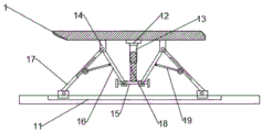
Referring to fig. 3, on the basis of embodiment 1, the lifting device includes a third motor 12, an output end of the third motor 12 is fixedly connected with a threaded sleeve 13, a second threaded rod 18 is connected in the threaded sleeve 13, the second threaded rod 18 is connected with the threaded sleeve 13 through a thread, a cross rod 15 is fixedly connected to a bottom end of the second threaded rod 18, two limit blocks are fixedly connected to two ends of the cross rod 15, two first sliders are symmetrically sleeved on the cross rod 15, the first sliders are provided with guide holes, the first sliders are hinged to one end of a second connecting rod 16, the other end of the second connecting rod 16 is hinged to a fixed block 14, the fixed block 14 is further hinged to one end of a third connecting rod 17, the other end of the third connecting rod 17 is hinged to the second slider, the second slider is slidably connected to a transverse plate 11, the upper end of the transverse plate 11 is provided with a second sliding groove for the second slider to slide, the third connecting rod 17 is provided with a second sliding rail for the sliding of the pulley, the pulley is connected with the moving rod 19, one end of the moving rod 19, which is far away from the pulley, is hinged with the middle part of the second connecting rod 16, when the third motor 12 drives the threaded sleeve 13 to rotate, the threaded sleeve 13 drives the threaded rod to move downwards under the action of the threads, when the threaded rod moves downwards, the first sliding block sleeved on the cross rod 15 moves towards two sides so as to rotate the second connecting rod 16, the second connecting rod 16 drives the third connecting rod 17 to rotate under the action of the moving rod 19, the included angle between the second connecting rod 16 and the third connecting rod 17 is reduced, the two second sliding blocks move oppositely on the second sliding groove so that the transverse plate 11 moves downwards, if the transverse plate 11 is required to be lifted, the third motor 12 is rotated reversely,
the utility model discloses a theory of operation is: when the polishing machine is used, the disc is driven to rotate by the first motor, the disc drives the eccentrically connected first connecting rod to move, the first connecting rod drives the clamping block 5 to slide to clamp and fix a to-be-polished object, the first threaded rod 8 is driven to rotate by the second motor, the threaded block is driven by the first threaded rod 8 to move left and right to enable the polishing machine to move left and right, the threaded sleeve 13 is driven by the third motor 12 to drive the threaded rod to move downwards under the action of threads, when the threaded rod moves downwards, the first sliding block sleeved on the transverse rod 15 moves towards two sides to enable the second connecting rod 16 to rotate, the second connecting rod 16 drives the third connecting rod 17 to rotate under the action of the moving rod 19, the included angle between the second connecting rod 16 and the third connecting rod 17 is reduced, the two second sliding blocks move oppositely on the second sliding grooves to enable the transverse plate 11 to move downwards, to raise the horizontal plate 11, the third motor 12 may be rotated in reverse.
It is obvious to a person skilled in the art that the invention is not restricted to details of the above-described exemplary embodiments, but that it can be implemented in other specific forms without departing from the spirit or essential characteristics of the invention. The present embodiments are therefore to be considered in all respects as illustrative and not restrictive, the scope of the invention being indicated by the appended claims rather than by the foregoing description, and all changes which come within the meaning and range of equivalency of the claims are therefore intended to be embraced therein. Any reference sign in a claim should not be construed as limiting the claim concerned.
Furthermore, it should be understood that although the present description refers to embodiments, not every embodiment may contain only a single embodiment, and such description is for clarity only, and those skilled in the art should integrate the description, and the embodiments may be combined as appropriate to form other embodiments understood by those skilled in the art.
Claims (5)
1. The automobile interior trim panel polishing tool comprises a polishing bin (1) and is characterized in that a placing table (3) is installed at the bottom in the polishing bin (1), clamping devices are installed on two sides of the placing table (3), a transverse plate (11) is slidably installed in the polishing bin (1), a fixing box (9) is installed at the bottom end of the transverse plate (11), a second motor (7) is installed on the outer side wall of the fixing box (9), a first threaded rod (8) is connected to one side, penetrating through one side of the fixing box (9), of the output end of the second motor (7), one end, far away from the second motor (7), of the first threaded rod (8) is rotatably connected to one side of the fixing box (9) through a first bearing, a threaded block is sleeved on the first threaded rod (8), the threaded block is in threaded connection with the first threaded rod (8), and the fast bottom of the threaded block is fixedly connected with a polishing machine, the lifting device is installed at the upper end of the transverse plate (11) and comprises a third motor (12), a thread sleeve (13) is fixedly connected to the output end of the third motor (12), a second threaded rod (18) is connected to the thread sleeve (13) in the thread sleeve (13), the second threaded rod (18) is in threaded connection with the thread sleeve (13), a transverse rod (15) is fixedly connected to the bottom end of the second threaded rod (18), limit blocks are fixedly connected to the two ends of the transverse rod (15), two first sliding blocks are symmetrically sleeved on the transverse rod (15), guide holes are formed in the first sliding blocks, the first sliding blocks are hinged to one end of a second connecting rod (16), the other end of the second connecting rod (16) is hinged to a fixed block (14), the fixed block (14) is hinged to one end of a third connecting rod (17), and the other end of the third connecting rod (17) is hinged to the second sliding block, the second slider and diaphragm (11) sliding connection, the gliding second spout of confession second slider is seted up to diaphragm (11) upper end, set up on third connecting rod (17) and supply the gliding second slide rail of pulley, the pulley is connected with carriage release lever (19), pulley one end is kept away from in carriage release lever (19) and second connecting rod (16) middle part is articulated to be connected.
2. The automotive interior panel grinding tool according to claim 1, wherein the clamping device comprises a support rod (4), a first motor is fixedly mounted at the top end of the support rod (4), a disc is fixedly mounted at the output end of the first motor, the disc is eccentrically hinged to a first connecting rod, a clamping block (5) is connected to the other end of the first connecting rod, and the clamping block (5) is slidably connected with the placing table (3).
3. The automotive interior board grinding tool according to claim 1, wherein an exhaust fan (6) is mounted on a rear side wall of the grinding chamber (1).
4. The automotive interior board grinding tool according to claim 3, characterized in that a plurality of universal wheels (2) are further mounted at the bottom of the grinding chamber (1).
5. The automotive interior board grinding tool according to claim 1, wherein telescopic rods (10) are mounted on two sides of the bottom of the transverse plate (11), a spring is sleeved outside each telescopic rod (10), one end of the spring is connected with the bottom end of the transverse plate (11), and the other end of the spring is connected with the bottom of the grinding bin (1).
Priority Applications (1)
| Application Number | Priority Date | Filing Date | Title |
|---|---|---|---|
| CN202022994120.1U CN214025006U (en) | 2020-12-14 | 2020-12-14 | Automotive interior board frock of polishing |
Applications Claiming Priority (1)
| Application Number | Priority Date | Filing Date | Title |
|---|---|---|---|
| CN202022994120.1U CN214025006U (en) | 2020-12-14 | 2020-12-14 | Automotive interior board frock of polishing |
Publications (1)
| Publication Number | Publication Date |
|---|---|
| CN214025006U true CN214025006U (en) | 2021-08-24 |
Family
ID=77336674
Family Applications (1)
| Application Number | Title | Priority Date | Filing Date |
|---|---|---|---|
| CN202022994120.1U Active CN214025006U (en) | 2020-12-14 | 2020-12-14 | Automotive interior board frock of polishing |
Country Status (1)
| Country | Link |
|---|---|
| CN (1) | CN214025006U (en) |
-
2020
- 2020-12-14 CN CN202022994120.1U patent/CN214025006U/en active Active
Similar Documents
| Publication | Publication Date | Title |
|---|---|---|
| CN208467994U (en) | Surface grinding device is used in a kind of casting of auto parts and components | |
| CN111360651B (en) | Multi-angle grinding machine for surface of intelligent pantograph carbon slide plate and grinding method thereof | |
| CN113103135A (en) | Walking type plate polishing device | |
| CN214025006U (en) | Automotive interior board frock of polishing | |
| CN218776292U (en) | Surface grinding device is used in processing of leaf spring support | |
| CN214186541U (en) | Polishing table with adjusting function | |
| CN215659476U (en) | Grinding device is used in steel casting production | |
| CN212470774U (en) | Numerical control crystal rounding machine | |
| CN211439938U (en) | Roller frame for placing, storing and taking grinding machine working roller | |
| CN208913569U (en) | A kind of profile welding angle-cleaning machine | |
| CN218801048U (en) | Platform length adjustable formula flat grinder | |
| CN215920080U (en) | Machining is with effectual burnishing machine of location | |
| CN112692660A (en) | Transmission shaft grinding device | |
| CN215920098U (en) | Burnishing device is used in production and processing of intelligence assembly accessories | |
| CN217045895U (en) | Burnishing device that machining used | |
| CN219380293U (en) | A polisher for panel beating surface polishing is polished | |
| CN213438899U (en) | Lifting polishing platform for impeller polishing machine | |
| CN218312398U (en) | Pin shaft surface polishing equipment | |
| CN214265168U (en) | Manual clamping device for polishing | |
| CN216608504U (en) | Polishing device | |
| CN213351991U (en) | Aluminum profile polishing machine | |
| CN217513548U (en) | Grinding device for optical lens | |
| CN220162102U (en) | Mechanical casting processing angle grinder | |
| CN218110438U (en) | Surface treatment device for machining | |
| CN220533788U (en) | Grinding and polishing equipment |
Legal Events
| Date | Code | Title | Description |
|---|---|---|---|
| GR01 | Patent grant | ||
| GR01 | Patent grant |