Transmission system underlying mechanism for wheel mill mixer
Technical Field
The utility model relates to a wheel grinds mixer field, in particular to wheel grinds for mixer transmission system put formula mechanism down.
Background
The wheel mill mixer is a machine type which combines wheel mill and mixing into one and is designed according to the advantages of wheel mill mixing equipment at home and abroad, and is widely applied to various aspects such as building materials and the like. The wheel mill type stirrer is also called a disc stirrer and is suitable for mixing and stirring various powder materials, is suitable for stirring and granulating aerated concrete block brick making equipment such as refractory clay, fly ash, tailing sand, furnace slag, molding sand and other materials, and is widely used in the industries of baking-free bricks, steam-cured bricks, refractory materials, aerated concrete mechanical ceramics, building materials and the like.
The transmission of wheel mill mixer generally can be the below of putting the formula and installing at the wheel mill agitator down, and the comparatively common formula drive mechanism of putting down of present wheel mill mixer has driving motor and belt pulley to constitute, is connected through the support column with driving motor and wheel mill mixer, and the rethread belt pulley transmits, but this kind of mode is when long-time implementation, appears the phenomenon that the belt lax appears for the belt pulley easily to the working effect of belt pulley transmission work has been reduced.
SUMMERY OF THE UTILITY MODEL
An object of the utility model is to provide a wheel grinds for agitator transmission system underneath type mechanism to solve the problem that proposes among the above-mentioned background art.
In order to achieve the above object, the utility model provides a following technical scheme: a transmission system underlying mechanism for a wheel mill stirrer comprises a wheel mill machine barrel, wherein the bottom of the wheel mill machine barrel is rotatably connected with a first belt pulley, the bottom of the wheel mill machine barrel is rotatably connected with a second belt pulley at a position which is positioned on one side of the first belt pulley, the outer walls of the first belt pulley and the second belt pulley are connected with an annular belt in a laminating manner, a U-shaped block is arranged at the position which is positioned at the bottom of the wheel mill machine barrel and between the first belt pulley and the second belt pulley, two I-shaped rotating rods are symmetrically arranged in an inner cavity of the U-shaped block, rollers are rotatably sleeved on the outer walls of the two I-shaped rotating rods, a U-shaped frame is fixedly connected to one side of each of the two I-shaped rotating rods, telescopic rods are fixedly connected to one side of each of the two U-shaped frames, extrusion grooves are symmetrically formed in two sides of the U-shaped blocks, and through holes are formed in one side of the inner walls of the two extrusion grooves, two the inner chamber of through-hole and the outer wall of the corresponding telescopic link in position slide and cup joint, two the equal fixedly connected with reset spring in one side of extrusion inslot wall, two reset spring's inner chamber and the outer wall activity of the corresponding telescopic link in position cup joint, two the equal fixedly connected with limiting plate in one side of reset spring, two one side of limiting plate and the one end fixed connection of the corresponding telescopic link in position.
Preferably, T-shaped sliding grooves are symmetrically formed in the top of the inner wall of the U-shaped block, T-shaped sliding blocks are sleeved in inner cavities of the two T-shaped sliding grooves in a sliding mode, and the bottoms of the two T-shaped sliding blocks are fixedly connected with the tops of the corresponding I-shaped rotating rods.
Preferably, the top of the inner wall of the U-shaped block and the position between the two T-shaped sliding grooves are provided with connecting holes, and the inner wall of each connecting hole is provided with uniformly distributed internal threads.
Preferably, the bottom of the barrel of the edge runner mill is fixedly connected with four support columns in a rectangular array, and a cross rod is fixedly connected between every two adjacent support columns.
Preferably, one of them one side fixedly connected with mounting panel of horizontal pole, one side fixedly connected with servo motor of mounting panel, servo motor's output is connected with the bottom transmission of second belt pulley.
Preferably, the servo motor is electrically connected with an external power supply through an external switch.
The utility model discloses a technological effect and advantage:
(1) the utility model utilizes the arrangement of the reset springs, the telescopic rods and the rollers to drive the two rollers to move oppositely through the two reset springs and the two telescopic rods, thereby enabling the two rollers to be attached and extrude the two sides of the endless belt, enabling the endless belt to be tightened constantly, and improving the working efficiency of the belt pulley transmission work;
(2) the utility model discloses utilize the setting of T type slider and T type spout, through the relative motion between T type slider and the T type spout to make I shape bull stick and gyro wheel can not break away from U type piece, improved the stability of I shape bull stick and gyro wheel motion.
Drawings
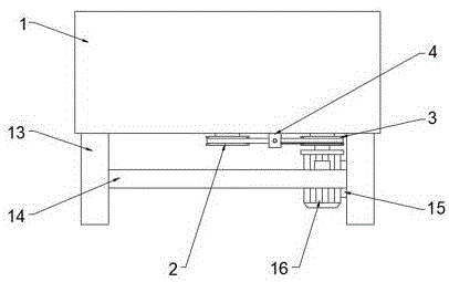
Fig. 1 is a schematic front structural view of the present invention.
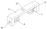
Fig. 2 is a schematic view of the U-shaped block of the present invention.
Fig. 3 is a schematic side sectional view of the U-shaped block of the present invention.
In the figure: 1. a barrel of an edge runner mill; 2. a first pulley; 3. a second pulley; 4. a U-shaped block; 5. an I-shaped rotating rod; 6. a roller; 7. a U-shaped frame; 8. a telescopic rod; 9. a return spring; 10. a limiting plate; 11. a T-shaped slider; 12. connecting holes; 13. a support pillar; 14. a cross bar; 15. mounting a plate; 16. a servo motor.
Detailed Description
The technical solutions in the embodiments of the present invention will be described clearly and completely with reference to the accompanying drawings in the embodiments of the present invention, and it is obvious that the described embodiments are only some embodiments of the present invention, not all embodiments. Based on the embodiments in the present invention, all other embodiments obtained by a person skilled in the art without creative work belong to the protection scope of the present invention.
The utility model provides a transmission system underlying mechanism for a wheel mill agitator as shown in figures 1-3, which comprises a wheel mill machine barrel 1, wherein the bottom of the wheel mill machine barrel 1 is rotationally connected with a first belt pulley 2, the bottom of the wheel mill machine barrel 1 is rotationally connected with a second belt pulley 3 at a position which is arranged at one side of the first belt pulley 2, the outer walls of the first belt pulley 2 and the second belt pulley 3 are connected with an annular belt in a fitting manner, a U-shaped block 4 is arranged at the bottom of the wheel mill machine barrel 1 and at a position which is arranged between the first belt pulley 2 and the second belt pulley 3, two I-shaped rotating rods 5 are symmetrically arranged in the inner cavity of the U-shaped block 4, the outer walls of the two I-shaped rotating rods 5 are rotationally sleeved with rollers 6, the cross section of each roller 6 is I-shaped, a U-shaped frame 7 is fixedly connected at one side of each of the two I-shaped rotating rods 5, and the U-shaped frame 7 plays a connecting transition role in connecting the telescopic rod 8 and the I-shaped rotating rods 5, telescopic rods 8 are fixedly connected to one sides of the two U-shaped frames 7, extrusion grooves are symmetrically formed in two sides of the U-shaped block 4, through holes are formed in one sides of inner walls of the two extrusion grooves, inner cavities of the two through holes are in sliding sleeve joint with outer walls of the telescopic rods 8 corresponding to the positions, return springs 9 are fixedly connected to one sides of the inner walls of the two extrusion grooves, the return springs 9 can elastically deform so as to drive the telescopic rods 8 to move through limiting plates 10, the inner cavities of the two return springs 9 are in movable sleeve joint with the outer walls of the telescopic rods 8 corresponding to the positions, limiting plates 10 are fixedly connected to one sides of the two return springs 9, and one sides of the two limiting plates 10 are fixedly connected with one ends of the telescopic rods 8 corresponding to the positions;
t-shaped sliding grooves are symmetrically formed in the top of the inner wall of the U-shaped block 4, the T-shaped sliding grooves and the T-shaped sliding blocks 11 are used for preventing the I-shaped rotating rod 5 and the roller 6 from being separated from the U-shaped block 4, the T-shaped sliding blocks 11 are sleeved in inner cavities of the two T-shaped sliding grooves in a sliding mode, and the bottoms of the two T-shaped sliding blocks 11 are fixedly connected with the top of the corresponding I-shaped rotating rod 5;
a connecting hole 12 is formed in the top of the inner wall of the U-shaped block 4 and located between the two T-shaped sliding grooves, the connecting hole 12 is used for installation work of the U-shaped block 4, and inner threads which are uniformly distributed are formed in the inner wall of the connecting hole 12;
the bottom of edge runner mill barrel 1 is four support columns 13 of rectangular array fixedly connected with, equal fixedly connected with horizontal pole 14 between two adjacent support columns 13, one side fixedly connected with mounting panel 15 of one of them horizontal pole 14, one side fixedly connected with servo motor 16 of mounting panel 15, open servo motor 16's external switch, servo motor 16 alright through first belt pulley 2, second belt pulley 3 and the work of endless belt drive wheel mill mixer, servo motor 16's output and second belt pulley 3's bottom transmission are connected.
The utility model discloses the theory of operation:
when the belt in the underneath type transmission mechanism of the wheel mill mixer is loosened due to long-term use, the U-shaped block 4 is firstly installed at the position between the first belt pulley 2 and the second belt pulley 3 through the connecting hole 12 and the positioning bolt, and the two rollers 6 are respectively pushed to the two sides of the inner wall of the U-shaped block 4, then the acting force applied to the roller 6 is slowly reduced, so that the roller 6 is slowly close to the annular belt under the action of the return spring 9, the telescopic rod 8, the U-shaped frame 7 and the I-shaped rotating rod 5, the annular belt enters the groove on the roller 6, when the roller 6 contacts the annular belt, the acting force can be completely removed, so that the installation of the tightening mechanism is completed, when the annular belt is in a slack state again, the two rollers 6 can continuously extrude the annular belt under the action of the return spring 9, so that the annular belt is deformed and is in a tight state.
In the description of the present invention, unless expressly stated or limited otherwise, the terms "disposed," "mounted," "connected," and "fixed" are to be construed broadly, e.g., as meaning either a fixed connection, a removable connection, or an integral part; can be mechanically or electrically connected; either directly or indirectly through intervening media, either internally or in any other relationship. The specific meaning of the above terms in the present invention can be understood in specific cases to those skilled in the art.
The utility model discloses the standard parts that use all can purchase from the market, and dysmorphism piece all can be customized according to the record of the description with the drawing.
Although embodiments of the present invention have been shown and described, it will be appreciated by those skilled in the art that changes, modifications, substitutions and alterations can be made in these embodiments without departing from the principles and spirit of the invention, the scope of which is defined in the appended claims and their equivalents.