CN214003010U - A kind of double guide chain plate based on conveyor line screw machine - Google Patents

A kind of double guide chain plate based on conveyor line screw machine Download PDF

Info

Publication number
CN214003010U
CN214003010U CN202022738166.7U CN202022738166U CN214003010U CN 214003010 U CN214003010 U CN 214003010U CN 202022738166 U CN202022738166 U CN 202022738166U CN 214003010 U CN214003010 U CN 214003010U
Authority
CN
China
Prior art keywords
plate
mounting plate
screw machine
conveyor line
movable shaft
Prior art date
Legal status (The legal status is an assumption and is not a legal conclusion. Google has not performed a legal analysis and makes no representation as to the accuracy of the status listed.)
Active
Application number
CN202022738166.7U
Other languages
Chinese (zh)
Inventor
夏雪刚
Current Assignee (The listed assignees may be inaccurate. Google has not performed a legal analysis and makes no representation or warranty as to the accuracy of the list.)
Pinzhan Energy Technology Anhui Co ltd
Original Assignee
Xinglongxu Automation Equipment Suzhou Co Ltd
Priority date (The priority date is an assumption and is not a legal conclusion. Google has not performed a legal analysis and makes no representation as to the accuracy of the date listed.)
Filing date
Publication date
Application filed by Xinglongxu Automation Equipment Suzhou Co Ltd filed Critical Xinglongxu Automation Equipment Suzhou Co Ltd
Priority to CN202022738166.7U priority Critical patent/CN214003010U/en
Application granted granted Critical
Publication of CN214003010U publication Critical patent/CN214003010U/en
Active legal-status Critical Current
Anticipated expiration legal-status Critical

Links

Images

Landscapes

  • Screw Conveyors (AREA)

Abstract

本实用新型适用于提升机设备技术领域,提供了一种基于输送线螺旋机的双导链板,包括有底座,所述底座顶端一侧焊接连接有支撑柱,且支撑柱顶端固定连接有第一安装板,并且该第一安装板内部嵌合安装有第一链板,所述第一安装板一侧固定安装有转动件,且转动件另一端转动连接有第二安装板。本实用新型中,在限位机构的作用下,通过转动T型杆,可以使其在支撑板内旋转移动,从而带动着抵块挤压限位板,配合预设复位弹簧的拉力,可以使其限位板能够调节角度,通过两个可调节角度的限位板,可以将其第一链板表面移动的物料进行限位移动,使其物料靠第一链板的中端位置,防止物料在移动过程中发生掉落的情况。
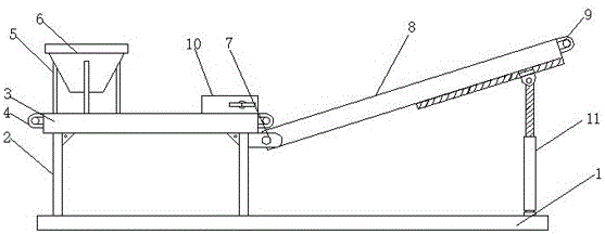
Figure 202022738166

The utility model is suitable for the technical field of hoist equipment, and provides a double guide chain plate based on a conveyor line screw machine, which comprises a base, a support column is welded and connected to one side of the top of the base, and a first support column is fixedly connected to the top of the support column. A mounting plate is fitted with a first chain plate inside the first mounting plate, a rotating member is fixedly mounted on one side of the first mounting plate, and a second mounting plate is rotatably connected to the other end of the rotating member. In the utility model, under the action of the limit mechanism, by rotating the T-shaped rod, it can rotate and move in the support plate, thereby driving the abutting block to squeeze the limit plate, and with the tension of the preset return spring, the The limit plate can adjust the angle. Through the two angle-adjustable limit plates, the material moving on the surface of the first chain plate can be moved in a limited position, so that the material is at the middle end of the first chain plate, preventing the material from moving. Falling while moving.

Figure 202022738166

Description

Two link joint of leading based on transfer chain screw machine
Technical Field
The utility model belongs to the technical field of lifting machine equipment, especially, relate to a two link joints of leading based on transfer chain screw machine.
Background
The spiral elevator, such as mine elevator, dam-crossing elevator, etc., can be called elevator, overhead traveling crane, hoist, stable car, crane, hoist, etc. in a broad sense, the elevator generally refers to large-scale mechanical equipment with large power and strong lifting capacity, and is used for vertically lifting limestone, equal-block granular materials, and powdery materials such as raw materials, cement, coal powder, etc. which pass through the crusher, and the materials can be transmitted at different heights through the chain guiding plate with a double-guiding structure.
The two link joints that lead of current transfer chain screw machine, at its in-process that uses, the height adjustment process of the link joint that leads of one end is loaded down with trivial details, is difficult for the operation, and the device does not possess spacing function of carrying, makes the condition that its material easily appears dropping.
SUMMERY OF THE UTILITY MODEL
The utility model provides a two link joints of leading based on transfer chain screw machine aims at solving current transfer chain screw machine two link joints of leading, and the high adjustment process of the link joint of leading of one end is loaded down with trivial details, is difficult for the operation, and the device does not possess spacing transport's function, makes the problem that drops easily appear in its material.
The utility model is realized in such a way, a double-guide chain plate based on a conveyor line screw machine comprises a base, one side of the top end of the base is welded and connected with a support column, the top end of the support column is fixedly connected with a first mounting plate, the first mounting plate is internally embedded and installed with the first chain plate, one side of the first mounting plate is fixedly installed with a rotating part, the other end of the rotating part is rotatably connected with a second mounting plate, the second mounting plate is internally embedded and installed with a second chain plate, the top end of the first mounting plate is installed with a limiting mechanism, the limiting mechanism comprises a support plate welded and connected with the top end of the first mounting plate, the inner wall of the support plate is fixedly connected with a first movable shaft, the other end of the first movable shaft is rotatably connected with a limiting plate, a reset spring is fixedly connected between the limiting plate and the support plate, and the inner part of the support plate is in threaded connection with a T-shaped rod, and one end of the supporting plate is fixedly connected with a supporting block, and a lifting mechanism is arranged between the second mounting plate and the base.
Preferably, first mounting panel top welded connection has the bracing piece, and bracing piece top welded connection has the feeder hopper.
Preferably, the abutting block is movably connected with the limiting plate, and the abutting block and the supporting plate form a telescopic structure through a T-shaped rod.
Preferably, the limiting plate is movably connected with the top end of the first chain plate, and the limiting plate and the supporting plate form a rotating structure through the first movable shaft.
Preferably, elevating system including with base top fixed connection's bearing, and the bearing top rotates and is connected with the sleeve, the inside threaded connection of sleeve has the threaded rod, and the threaded rod top rotates and is connected with the second loose axle, second mounting plate bottom end fixedly connected with spout, and the inside cup joint of spout is inserted and is equipped with the slider to slider and second loose axle fixed connection.
Preferably, the second movable shaft forms a sliding structure with the sliding groove through a sliding block, and the sleeve forms a rotating structure with the base through a bearing.
Compared with the prior art, the beneficial effects of the utility model are that:
1. the utility model discloses in, under stop gear's effect, through rotating T type pole, can make it remove in the backup pad internal rotation to driving and supporting piece extrusion limiting plate, reset spring's pulling force is predetermine in the cooperation, can make its limiting plate can angle regulation, through two angle regulation's limiting plate, can carry out spacing removal with the material of its first link joint surface removal, make its material lean on the middle-end position of first link joint, prevent that the material from taking place the condition that drops at the removal in-process.
2. The utility model discloses in, under elevating system's effect, through rotating the sleeve, can make its inside threaded rod move telescopically to driving the height of top second loose axle, pushing up the one end of moving the second mounting panel through the second loose axle, making its angle regulation, thereby adjusting the height of one end, easy operation, and labour saving and time saving.
Drawings
Fig. 1 is a schematic structural view of the present invention;
fig. 2 is a schematic structural view of the spacing mechanism in the present invention from the top;
FIG. 3 is a schematic side view of the lifting mechanism of the present invention;
fig. 4 is an enlarged schematic view of a portion a in fig. 3.
In the figure: 1. a base; 2. a support pillar; 3. a first mounting plate; 4. a first link plate; 5. a support bar; 6. a feed hopper; 7. a rotating member; 8. a second mounting plate; 9. a second link plate; 10. a limiting mechanism; 1001. a support plate; 1002. a first movable shaft; 1003. a limiting plate; 1004. a return spring; 1005. a T-shaped rod; 1006. a resisting block; 11. a lifting mechanism; 1101. a bearing; 1102. a sleeve; 1103. a threaded rod; 1104. a second movable shaft; 1105. a chute; 1106. a slide block.
Detailed Description
In order to make the objects, technical solutions and advantages of the present invention more clearly understood, the present invention is further described in detail below with reference to the accompanying drawings and embodiments. It should be understood that the specific embodiments described herein are merely illustrative of the invention and are not intended to limit the invention.
Referring to fig. 1-4, the utility model provides a double-guide chain plate based on a conveyor line screw machine, which comprises a base 1, a support column 2 welded on one side of the top end of the base 1, a first mounting plate 3 fixedly connected on the top end of the support column 2, a first chain plate 4 embedded in the first mounting plate 3, a rotating member 7 fixedly mounted on one side of the first mounting plate 3, a second mounting plate 8 rotatably connected on the other end of the rotating member 7, a second chain plate 9 embedded in the second mounting plate 8, a limiting mechanism 10 mounted on the top end of the first mounting plate 3, the limiting mechanism 10 comprising a support plate 1001 welded on the top end of the first mounting plate 3, a first movable shaft 1002 fixedly connected on the inner wall of the support plate 1001, a limiting plate 1003 rotatably connected on the other end of the first movable shaft 1002, and a reset spring 1004 fixedly connected between the limiting plate 1003 and the support plate 1001, a T-shaped rod 1005 is screwed inside the supporting plate 1001, a supporting block 1006 is fixedly connected to one end of the supporting plate 1001, and a lifting mechanism 11 is installed between the second mounting plate 8 and the base 1.
In this embodiment, rotating T-shaped rod 1005, T-shaped rod 1005 can rotate in backup pad 1001 and move, drives to support piece 1006 and extrudes the one end of limiting plate 1003, and reset spring 1004's pulling force is predetermine in the cooperation, can make its limiting plate 1003 angle regulation.
Further, 3 top welded connections of first mounting panel have bracing piece 5, and 5 top welded connections of bracing piece have feeder hopper 6.
In this embodiment, the material in the feeding hopper 6 can fall into the top end of the first chain plate 4 for transportation.
Further, the abutting block 1006 is movably connected with the limiting plate 1003, and the abutting block 1006 forms a telescopic structure with the supporting plate 1001 through the T-shaped rod 1005.
In the present embodiment, one end of the stopper plate 1003 is rotatable by the first movable shaft 1002.
Further, the limiting plate 1003 is movably connected with the top end of the first chain plate 4, and the limiting plate 1003 and the supporting plate 1001 form a rotating structure through a first movable shaft 1002.
In the present embodiment, the two opposing stopper plates 1003 can move angularly on the surface of the first link plate 4.
Further, the lifting mechanism 11 includes the bearing 1101 with base 1 top fixed connection, and the bearing 1101 top rotates and is connected with sleeve 1102, and the inside threaded connection of sleeve 1102 has threaded rod 1103, and threaded rod 1103 top rotates and is connected with second loose axle 1104, and second mounting panel 8 bottom fixed connection has spout 1105, and inside the cup jointing of spout 1105 is inserted and is equipped with slider 1106, and slider 1106 and second loose axle 1104 fixed connection.
In this embodiment, the sleeve 1102 is rotated by rotating the sleeve 1102, the sleeve 1102 is rotated by the bearing 1101, and the threaded rod 1103 internally screwed can be moved in an extending and contracting manner when the sleeve 1102 is rotated.
Further, the second movable shaft 1104 and the slide groove 1105 form a sliding structure via the slider 1106, and the sleeve 1102 and the base 1 form a rotating structure via the bearing 1101.
In this embodiment, the threaded rod 1103 may drive the second movable shaft 1104 to move up and down, the second movable shaft 1104 may slide in the sliding slot 1105 via the sliding block 1106, and the threaded rod 1103 may rotate by the angle of the second movable shaft 1104.
The utility model discloses a theory of operation and use flow: when the device is used, firstly, the sleeve 1102 is manually rotated, the sleeve 1102 rotates through the bearing 1101, when the sleeve 1102 rotates, the threaded rod 1103 connected with the internal thread moves in a stretching way, the threaded rod 1103 drives the second movable shaft 1104 at the top end to move in a lifting way, the second movable shaft 1104 slides in the sliding groove 1105 through the sliding block 1106, meanwhile, the threaded rod 1103 adjusts the height of one end of the second mounting plate 8 through the rotation angle of the second movable shaft 1104, the other end of the second mounting plate 8 rotates through the rotation angle of the rotating part 7, then the T-shaped rod 1005 is manually rotated, the T-shaped rod 1005 rotates and moves in the supporting plate 1001 to drive the abutting block 1006 to extrude one end of the limiting plate 1003, the other end of the limiting plate 1003 rotates through the rotation angle of the first movable shaft 1002 to adjust the two limiting plates 1003 to proper positions, when the material removed on 4 surfaces of first link joint, contacted two limiting plates 1003, limiting plate 1003 made its material remove between two parties, just so accomplished the utility model discloses an operating principle.
The above description is only exemplary of the present invention and should not be taken as limiting the scope of the present invention, as any modifications, equivalents, improvements and the like made within the spirit and principles of the present invention are intended to be included within the scope of the present invention.

Claims (6)

1.一种基于输送线螺旋机的双导链板,包括有底座(1),其特征在于:所述底座(1)顶端一侧焊接连接有支撑柱(2),且支撑柱(2)顶端固定连接有第一安装板(3),并且该第一安装板(3)内部嵌合安装有第一链板(4),所述第一安装板(3)一侧固定安装有转动件(7),且转动件(7)另一端转动连接有第二安装板(8),并且该第二安装板(8)内部嵌合安装有第二链板(9),所述第一安装板(3)顶端安装有限位机构(10),且限位机构(10)包括有与第一安装板(3)顶端焊接连接的支撑板(1001),所述支撑板(1001)内壁固定连接有第一活动轴(1002),且第一活动轴(1002)另一端转动连接有限位板(1003),并且该限位板(1003)与支撑板(1001)之间固定连接有复位弹簧(1004),所述支撑板(1001)内部螺纹连接有T型杆(1005),且支撑板(1001)一端固定连接有抵块(1006),所述第二安装板(8)与底座(1)之间安装有升降机构(11)。1. A double chain guide plate based on a conveyor line screw machine, comprising a base (1), characterized in that: a support column (2) is welded and connected to one side of the top of the base (1), and the support column (2) A first mounting plate (3) is fixedly connected to the top, and a first chain plate (4) is fitted inside the first mounting plate (3), and a rotating member is fixedly mounted on one side of the first mounting plate (3). (7), and the other end of the rotating member (7) is rotatably connected with a second mounting plate (8), and the second mounting plate (8) is fitted with a second chain plate (9) inside the second mounting plate (8). A limiting mechanism (10) is installed at the top of the plate (3), and the limiting mechanism (10) includes a support plate (1001) welded to the top of the first mounting plate (3), and the inner wall of the support plate (1001) is fixedly connected There is a first movable shaft (1002), and the other end of the first movable shaft (1002) is rotatably connected to a limit plate (1003), and a return spring ( 1004), a T-bar (1005) is threadedly connected inside the support plate (1001), and a block (1006) is fixedly connected to one end of the support plate (1001), and the second mounting plate (8) is connected to the base (1). A lift mechanism (11) is installed between ). 2.如权利要求1所述的一种基于输送线螺旋机的双导链板,其特征在于:所述第一安装板(3)顶端焊接连接有支撑杆(5),且支撑杆(5)顶端焊接连接有进料斗(6)。2. A double guide plate based on a conveyor line screw machine according to claim 1, characterized in that: a support rod (5) is welded and connected to the top of the first mounting plate (3), and the support rod (5) ) top is welded with a feeding hopper (6). 3.如权利要求1所述的一种基于输送线螺旋机的双导链板,其特征在于:所述抵块(1006)与限位板(1003)活动连接,所述抵块(1006)通过T型杆(1005)与支撑板(1001)构成伸缩结构。3. The double guide chain plate based on a conveyor line screw machine according to claim 1, characterized in that: the abutment block (1006) is movably connected with the limit plate (1003), and the abutment block (1006) A telescopic structure is formed by the T-bar (1005) and the support plate (1001). 4.如权利要求1所述的一种基于输送线螺旋机的双导链板,其特征在于:所述限位板(1003)与第一链板(4)顶端活动连接,且限位板(1003)通过第一活动轴(1002)与支撑板(1001)构成旋转结构。4. A double guide chain plate based on a conveyor line screw machine according to claim 1, characterized in that: the limit plate (1003) is movably connected to the top of the first chain plate (4), and the limit plate (1003) (1003) A rotating structure is formed by the first movable shaft (1002) and the support plate (1001). 5.如权利要求1所述的一种基于输送线螺旋机的双导链板,其特征在于:所述升降机构(11)包括有与底座(1)顶端固定连接的轴承(1101),且轴承(1101)顶端转动连接有套筒(1102),所述套筒(1102)内部螺纹连接有螺纹杆(1103),且螺纹杆(1103)顶端转动连接有第二活动轴(1104),所述第二安装板(8)底端固定连接有滑槽(1105),且滑槽(1105)内部套接插设有滑块(1106),并且滑块(1106)与第二活动轴(1104)固定连接。5. A double guide chain plate based on a conveyor line screw machine according to claim 1, characterized in that: the lifting mechanism (11) comprises a bearing (1101) fixedly connected to the top of the base (1), and A sleeve (1102) is rotatably connected to the top of the bearing (1101), a threaded rod (1103) is threadedly connected inside the sleeve (1102), and a second movable shaft (1104) is rotatably connected to the top of the threaded rod (1103). A sliding groove (1105) is fixedly connected to the bottom end of the second mounting plate (8), and a sliding block (1106) is sleeved and inserted inside the sliding groove (1105), and the sliding block (1106) is connected to the second movable shaft (1104). ) fixed connection. 6.如权利要求5所述的一种基于输送线螺旋机的双导链板,其特征在于:所述第二活动轴(1104)通过滑块(1106)与滑槽(1105)构成滑动结构,所述套筒(1102)通过轴承(1101)与底座(1)构成旋转结构。6 . The double guide plate based on a conveyor line screw machine according to claim 5 , wherein the second movable shaft ( 1104 ) forms a sliding structure through a slider ( 1106 ) and a chute ( 1105 ). 7 . , the sleeve (1102) forms a rotating structure with the base (1) through the bearing (1101).
CN202022738166.7U 2020-11-24 2020-11-24 A kind of double guide chain plate based on conveyor line screw machine Active CN214003010U (en)

Priority Applications (1)

Application Number Priority Date Filing Date Title
CN202022738166.7U CN214003010U (en) 2020-11-24 2020-11-24 A kind of double guide chain plate based on conveyor line screw machine

Applications Claiming Priority (1)

Application Number Priority Date Filing Date Title
CN202022738166.7U CN214003010U (en) 2020-11-24 2020-11-24 A kind of double guide chain plate based on conveyor line screw machine

Publications (1)

Publication Number Publication Date
CN214003010U true CN214003010U (en) 2021-08-20

Family

ID=77306242

Family Applications (1)

Application Number Title Priority Date Filing Date
CN202022738166.7U Active CN214003010U (en) 2020-11-24 2020-11-24 A kind of double guide chain plate based on conveyor line screw machine

Country Status (1)

Country Link
CN (1) CN214003010U (en)

Cited By (4)

* Cited by examiner, † Cited by third party
Publication number Priority date Publication date Assignee Title
CN113942782A (en) * 2021-10-22 2022-01-18 无锡市金华屹圆科技有限公司 Full-automatic assembling machine for water inlet pipe of washing machine
CN114176241A (en) * 2022-01-20 2022-03-15 红云红河烟草(集团)有限责任公司 Material guide device for tobacco shredding
CN118560962A (en) * 2024-06-06 2024-08-30 葛洲坝石门特种水泥有限公司 A cement ton bag conveying equipment
CN119660304A (en) * 2025-02-21 2025-03-21 爱安特(常州)精密机械有限公司 Conveyer with scrape material structure

Similar Documents

Publication Publication Date Title
CN201217563Y (en) Variable angle chute
CN203529167U (en) Concrete gravel storage hopper with brake discharge door
CN110526020B (en) A kind of automatic inversion and dislocation stacking device for carton packaging
CN104139949B (en) Vertical charger
CN212334487U (en) Bucket elevator
CN211337626U (en) Inclined spiral conveyor with adjustable angle
CN105712028B (en) Compact belt conveyer
CN208070863U (en) Fine grained and granular material charging gear
CN108455320A (en) Freight transport vehicle material temper mill
CN106744481A (en) A kind of construction material elevator large scale equipment
CN203332927U (en) Belt conveyor incline section multipoint discharging device
CN217437167U (en) Aggregate bulk loader slowing device for avoiding sand damage to blanking pipe
CN214030445U (en) A screw hoist with a screw hoist chain plate
CN213170424U (en) Storage device is used in chemical fertilizer production
CN213445175U (en) Discharge apparatus of non-woven fabrics raw materials
CN223087146U (en) Promote feeding structure
CN213801517U (en) Auxiliary feeding device for cement kiln
CN210815101U (en) Bulk drug pelletizes and uses device convenient to it is reinforced
CN219340732U (en) Profile steel production conveying mechanism
CN108034440A (en) A kind of briquette height controller and method
CN223356613U (en) Vibrating feeder
CN208531813U (en) A kind of coiled material feeding conveying device
CN205499012U (en) Raw materials transfer device is used in plane materiel production
CN219688449U (en) Novel lifting bag pouring machine
CN221092900U (en) Rotary power device of automatic car loader

Legal Events

Date Code Title Description
GR01 Patent grant
GR01 Patent grant
TR01 Transfer of patent right

Effective date of registration: 20241114

Address after: 24 # Factory Building, New Materials Industrial Park, Wanjiang Jiangnan Emerging Industry Concentration Zone, Chizhou City, Anhui Province, China 247100

Patentee after: Pinzhan Energy Technology (Anhui) Co.,Ltd.

Country or region after: China

Address before: No.3 Guangda Road, Zhitang Town, Changshu City, Suzhou City, Jiangsu Province

Patentee before: Xinglongxu automation equipment (Suzhou) Co.,Ltd.

Country or region before: China