CN213977350U - Denitrogenation biological aerated filter - Google Patents
Denitrogenation biological aerated filter Download PDFInfo
- Publication number
- CN213977350U CN213977350U CN202022650624.1U CN202022650624U CN213977350U CN 213977350 U CN213977350 U CN 213977350U CN 202022650624 U CN202022650624 U CN 202022650624U CN 213977350 U CN213977350 U CN 213977350U
- Authority
- CN
- China
- Prior art keywords
- aeration
- tank
- aeration tank
- denitrification
- pipe
- Prior art date
- Legal status (The legal status is an assumption and is not a legal conclusion. Google has not performed a legal analysis and makes no representation as to the accuracy of the status listed.)
- Expired - Fee Related
Links
- 238000005273 aeration Methods 0.000 claims abstract description 87
- 239000010865 sewage Substances 0.000 claims abstract description 29
- 239000012535 impurity Substances 0.000 claims abstract description 20
- 238000003756 stirring Methods 0.000 claims abstract description 8
- 238000001914 filtration Methods 0.000 claims abstract description 7
- XLYOFNOQVPJJNP-UHFFFAOYSA-N water Substances O XLYOFNOQVPJJNP-UHFFFAOYSA-N 0.000 claims description 15
- 239000007788 liquid Substances 0.000 claims description 14
- 239000003814 drug Substances 0.000 claims description 10
- 238000007789 sealing Methods 0.000 claims description 9
- 230000005540 biological transmission Effects 0.000 claims description 6
- 239000000126 substance Substances 0.000 claims description 4
- IJGRMHOSHXDMSA-UHFFFAOYSA-N Atomic nitrogen Chemical compound N#N IJGRMHOSHXDMSA-UHFFFAOYSA-N 0.000 abstract description 11
- 229910002651 NO3 Inorganic materials 0.000 abstract description 5
- NHNBFGGVMKEFGY-UHFFFAOYSA-N Nitrate Chemical compound [O-][N+]([O-])=O NHNBFGGVMKEFGY-UHFFFAOYSA-N 0.000 abstract description 5
- 229910052757 nitrogen Inorganic materials 0.000 abstract description 5
- 231100000252 nontoxic Toxicity 0.000 abstract description 4
- 230000003000 nontoxic effect Effects 0.000 abstract description 4
- 238000000034 method Methods 0.000 description 12
- 230000008569 process Effects 0.000 description 8
- QGZKDVFQNNGYKY-UHFFFAOYSA-N Ammonia Chemical compound N QGZKDVFQNNGYKY-UHFFFAOYSA-N 0.000 description 4
- 241000894006 Bacteria Species 0.000 description 4
- 230000009471 action Effects 0.000 description 3
- QVGXLLKOCUKJST-UHFFFAOYSA-N atomic oxygen Chemical compound [O] QVGXLLKOCUKJST-UHFFFAOYSA-N 0.000 description 3
- 239000001301 oxygen Substances 0.000 description 3
- 229910052760 oxygen Inorganic materials 0.000 description 3
- 239000010802 sludge Substances 0.000 description 3
- 229910021529 ammonia Inorganic materials 0.000 description 2
- XKMRRTOUMJRJIA-UHFFFAOYSA-N ammonia nh3 Chemical compound N.N XKMRRTOUMJRJIA-UHFFFAOYSA-N 0.000 description 2
- 230000000694 effects Effects 0.000 description 2
- 244000005700 microbiome Species 0.000 description 2
- 230000001502 supplementing effect Effects 0.000 description 2
- OKTJSMMVPCPJKN-UHFFFAOYSA-N Carbon Chemical compound [C] OKTJSMMVPCPJKN-UHFFFAOYSA-N 0.000 description 1
- IOVCWXUNBOPUCH-UHFFFAOYSA-M Nitrite anion Chemical compound [O-]N=O IOVCWXUNBOPUCH-UHFFFAOYSA-M 0.000 description 1
- 230000004075 alteration Effects 0.000 description 1
- 230000009286 beneficial effect Effects 0.000 description 1
- 229910052799 carbon Inorganic materials 0.000 description 1
- 238000009960 carding Methods 0.000 description 1
- 230000015556 catabolic process Effects 0.000 description 1
- 238000006243 chemical reaction Methods 0.000 description 1
- 230000007547 defect Effects 0.000 description 1
- 238000006731 degradation reaction Methods 0.000 description 1
- 229910001873 dinitrogen Inorganic materials 0.000 description 1
- 238000007599 discharging Methods 0.000 description 1
- 229940079593 drug Drugs 0.000 description 1
- 239000000945 filler Substances 0.000 description 1
- 230000014759 maintenance of location Effects 0.000 description 1
- 239000000463 material Substances 0.000 description 1
- 230000007246 mechanism Effects 0.000 description 1
- 238000012986 modification Methods 0.000 description 1
- 230000004048 modification Effects 0.000 description 1
- 239000002957 persistent organic pollutant Substances 0.000 description 1
- 239000011150 reinforced concrete Substances 0.000 description 1
- 238000006467 substitution reaction Methods 0.000 description 1
Images
Landscapes
- Purification Treatments By Anaerobic Or Anaerobic And Aerobic Bacteria Or Animals (AREA)
Abstract
The utility model discloses a denitrification aeration biological filter, which comprises an aeration tank, wherein an open equipment room is arranged outside the bottom layer of the aeration tank, a driving motor and an aeration pump are arranged at the bottom of the equipment room, a first bracket is arranged at the bottom of the aeration tank, an aeration pipe is arranged on the first bracket, a plurality of aeration heads are arranged on the aeration pipe, a driving rod is arranged at the driving end of the driving motor, stirring blades are arranged at the top end of the driving rod, an opening is arranged on the side wall of the bottom of the aeration tank, a sewage conveying device is arranged at the opening, one end of the sewage conveying device is connected with a sealed tank, and an impurity filtering device is arranged above the aeration tank. Denitrifying the nitrate to generate non-toxic and harmless nitrogen.
Description
Technical Field
The utility model relates to a denitrogenation aeration technical field specifically is a denitrogenation biological aerated filter.
Background
The aeration tank is a biochemical reactor designed by people according to the characteristics of microorganisms, the degradation degree of organic pollutants is mainly determined by the aeration reaction conditions designed by people, the aeration tank utilizes an activated sludge method to treat sewage, certain sewage retention time is provided in the tank, the oxygen quantity required by aerobic microorganisms and the mixing condition of full contact of sewage and activated sludge are met, the aeration tank mainly comprises a tank body, an aeration system and a water inlet and a water outlet, the tank body is generally made of reinforced concrete, the plane shape of the tank body is rectangular, square, circular and the like, the utility model patent with the publication number of CN207581453U relates to a baffling type ammonia and nitrogen removal aeration biological filter tank, which mainly comprises a filter tank, the upper part of the left side wall of the filter tank is provided with a water inlet, the upper part of the right side wall is provided with a water outlet, a plurality of baffling filter units are arranged in the filter tank, and the baffling filter units comprise baffle plates, the water distribution device comprises a supporting plate and a filler frame, a water distribution channel is formed between two baffling filter units, a medicament supplementing device is arranged at the top of the water distribution channel, an alkalinity medicament or a carbon source is filled in the medicament supplementing device, in the actual life, substances such as nitrite and nitrate can be generated in a biological filter in the ammonia and nitrogen removal process, and the substances can be discharged into the air after denitrifying bacteria generate nontoxic and harmless nitrogen in an anaerobic environment.
SUMMERY OF THE UTILITY MODEL
Aiming at the defects of the prior art, the utility model provides a denitrification biological aerated filter, which solves the problem that the prior device can not process the substances such as nitrate in the biological filter.
In order to achieve the above purpose, the utility model discloses a following technical scheme realizes: a denitrification aeration biological filter, which comprises an aeration tank, wherein an open equipment room is arranged outside the bottom layer of the aeration tank, the bottom of the equipment room is provided with a driving motor and an aeration pump, the bottom of the aeration tank is provided with a first bracket, the first bracket is provided with aeration pipes, a plurality of aeration heads are arranged on the aeration pipes, a guide pipe is arranged between the aeration pump and the aeration pipe, a driving end of the driving motor is provided with a transmission rod, the top end of the transmission rod is provided with a stirring paddle, the side wall of the bottom of the aeration tank is provided with an opening, the opening is provided with a sewage conveying device, one end of the sewage conveying device is connected with a sealing tank, the top of the sealing tank is provided with a dosing device, the aeration tank is characterized in that an impurity filtering device is installed above the aeration tank, comb teeth are installed on the side wall of the aeration tank, an impurity outlet is formed in the side wall of the aeration tank, and a collecting box is installed below the impurity outlet and on the outer wall of the aeration tank.
Preferably, the impurity filtering device comprises a pair of bases arranged at the top end of the wall of the aeration tank, a pair of second supports are arranged on the bases, a conveyor belt is arranged between the second supports, a plurality of filter plates are arranged on the conveyor belt, and filter screens are arranged on the filter plates.
Preferably, the sewage conveying device comprises a liquid outlet pipe arranged on the opening, a water pump is arranged at one end of the liquid outlet pipe, a liquid inlet pipe is arranged at one end of the water pump, and the liquid inlet pipe is connected with the sealing tank.
Preferably, charge device including install in the box on sealed tank top, box internally mounted has the pillar, the guide rail is installed to the pillar side, install electric slide bar on the guide rail, the medicament box is installed to the electric slide bar bottom, the box with install electronic sliding door between the sealed tank.
Preferably, a bearing is arranged between the transmission rod and the aeration tank.
Preferably, a first waterproof end cover is mounted on the exterior of the bearing.
Preferably, a second waterproof end cap is mounted on the exterior of the conduit.
Preferably, the top end of the seal tank is provided with an air outlet.
Advantageous effects
The utility model provides a denitrogenation biological aerated filter possesses following beneficial effect, the utility model discloses increase and have the seal pot, fill the sewage after removing ammonia nitrogen removal with the biological filter into the seal pot, contain a large amount of denitrifying bacteria in the activated sludge in the seal pot, these denitrifying bacteria can produce the non-toxic harmless nitrogen gas with the nitrate material denitrification in the sewage in the environment of anaerobism after, in the air of discharging, more thoroughly that the process that will remove ammonia nitrogen removal goes on. Install charge device at the seal pot top, what put into in the charge device is the deoxidier, and the device can be got rid of the oxygen in the air in the seal pot, guarantees to be in the anaerobic environment relatively in the seal pot, guarantees denitrifying bacteria's effect maximize, increases work efficiency. The stirring mechanism is added in the aeration tank, so that sewage is in a flowing state, the service efficiency of the aeration tank is ensured to be accelerated, and the stirring sewage can also ensure that air sprayed from the aeration head is dissolved in the sewage more quickly.
Drawings
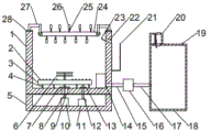
Fig. 1 is a front view of the present invention.
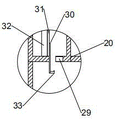
Fig. 2 is a partial sectional view of the drug adding device of the utility model.
In the figure: 1. an aeration tank; 2. an aeration head; 3. an aeration pipe; 4. a first bracket; 5. an equipment room; 6. a stirring paddle; 7. a first waterproof end cap; 8. a transmission rod; 9. a bearing; 10. a drive motor; 11. an aeration pump; 12. a conduit; 13. a second waterproof end cap; 14. an opening; 15. a liquid outlet pipe; 16. a water pump; 17. a liquid inlet pipe; 18. sealing the tank; 19. an air outlet; 20. a box body; 21. a collection box; 22. an impurity outlet; 23. comb teeth; 24. a conveyor belt; 25. a filter plate; 26. a filter screen; 27. a second bracket; 28. a base; 29. an electric sliding door; 30. an electric slide bar; 31. a guide rail; 32. a pillar; 33. a medicament box.
Detailed Description
The technical solutions in the embodiments of the present invention will be described clearly and completely with reference to the accompanying drawings in the embodiments of the present invention, and it is obvious that the described embodiments are only some embodiments of the present invention, not all embodiments. Based on the embodiments in the present invention, all other embodiments obtained by a person skilled in the art without creative work belong to the protection scope of the present invention.
Referring to fig. 1-2, the present invention provides a technical solution: a denitrification aeration biological filter comprises an aeration tank 1, wherein an open equipment room 5 is arranged outside the bottom layer of the aeration tank 1, a driving motor 10 and an aeration pump 11 are installed at the bottom of the equipment room 5, a first support 4 is installed at the bottom of the aeration tank 1, an aeration pipe 3 is installed on the first support 4, a plurality of aeration heads 2 are installed on the aeration pipe 3, a guide pipe 12 is installed between the aeration pump 11 and the aeration pipe 3, a driving rod 8 is installed at the driving end of the driving motor 10, a stirring paddle 6 is installed at the top end of the driving rod 8, an opening 14 is formed in the side wall of the bottom of the aeration tank 1, a sewage conveying device is installed at the opening 14, one end of the sewage conveying device is connected with a sealing tank 18, a dosing device is installed at the top of the sealing tank 18, an impurity filtering device is installed above the aeration tank 1, and comb teeth 23 are installed on the side wall of the aeration tank 1, the side wall of the aeration tank 1 is provided with an impurity outlet 22, the outer wall of the aeration tank 1 is positioned below the impurity outlet 22, a collection box 21 is installed on the lower portion of the impurity outlet 22, the impurity filtering device comprises a pair of bases 28 installed on the top end of the tank wall of the aeration tank 1, a pair of second supports 27 are installed on the bases 28, a conveyor belt 24 is installed between the second supports 27, a plurality of filter plates 25 are installed on the conveyor belt 24, filter screens 26 are installed on the filter plates 25, the sewage conveying device comprises a drain pipe 15 installed on the opening 14, a water pump 16 is installed at one end of the drain pipe 15, a liquid inlet pipe 17 is installed at one end of the water pump 16, the liquid inlet pipe 17 is connected with the sealing tank 18, the dosing device comprises a tank body 20 installed at the top end of the sealing tank 18, and a support column 32 is installed inside the tank body 20, guide rail 31 is installed to pillar 32 side, install electric slide bar 30 on the guide rail 31, medicament box 33 is installed to electric slide bar 30 bottom, box 20 with install electronic sliding door 29 between the seal pot 18, transfer line 8 with install bearing 9 between the aeration tank 1, bearing 9 externally mounted has first waterproof end cover 7, pipe 12 externally mounted has second waterproof end cover 13, venthole 19 is installed on seal pot 18 top.
The following working principles, detailed connecting means thereof, and the following main descriptions of the working principles and processes thereof are well known in the art, and will be referred to by those skilled in the art for the specific connection and operation sequence of the components in the present disclosure.
Example (b): when the denitrification aeration treatment is required to be carried out on the sewage, firstly, the sewage is filled into the aeration tank 1, then the aeration pump 11 is started, air is sprayed into the aeration tank 1 from the aeration head 2 along the aeration pipe 3, the sewage is aerated, simultaneously, the driving motor 10 is started, the driving motor 10 drives the stirring blades 6 to rotate through the transmission rod 8, so that the sewage has flowing capacity, in the sewage aeration process, a large amount of bubbles can bring impurities at the bottom of the sewage to the surface of the sewage, then, the conveying belt 24 is started, the impurities on the surface of the sewage can be fished up through the filter screen 26 on the conveying belt 24, the impurities on the filter screen 26 can be scraped through the carding of the comb teeth 23, the impurities enter the collecting box 21 from the impurity outlet 22 along the comb teeth 23, the water pump 16 is started after the aeration treatment, the sewage in the aeration tank 1 enters the sealed tank 18 along the liquid outlet pipe 15 and the liquid inlet pipe 17, the sewage is subjected to denitrification treatment, the electric sliding door 29 is opened, the electric sliding rod 30 is started again, the medicine box 33 is stretched into the sealed tank 18, oxygen in redundant air at the top of the sealed tank 18 can be removed by a deoxidizer in the medicine box 33, the sealed tank 18 is ensured to be in an anaerobic environment, and finally, the nitrate is denitrified to generate nontoxic and harmless nitrogen to be discharged into the air through denitrification.
It is noted that, herein, relational terms such as first and second, and the like may be used solely to distinguish one entity or action from another entity or action without necessarily requiring or implying any actual such relationship or order between such entities or actions. Also, the terms "comprises," "comprising," or any other variation thereof, are intended to cover a non-exclusive inclusion, such that a process, method, article, or apparatus that comprises a list of elements does not include only those elements but may include other elements not expressly listed or inherent to such process, method, article, or apparatus. Without further limitation. The use of the phrase "comprising one of the elements does not exclude the presence of other like elements in the process, method, article, or apparatus that comprises the element.
Although embodiments of the present invention have been shown and described, it will be appreciated by those skilled in the art that changes, modifications, substitutions and alterations can be made in these embodiments without departing from the principles and spirit of the invention, the scope of which is defined in the appended claims and their equivalents.
Claims (8)
1. The utility model provides a denitrification aeration biological filter, includes aeration tank (1), its characterized in that, aeration tank (1) bottom outside is equipped with open equipment room (5), driving motor (10) and aeration pump (11) are installed to equipment room (5) bottom, first support (4) are installed to aeration tank (1) bottom, install aeration pipe (3) on first support (4), install a plurality of aeration head (2) of quantity on aeration pipe (3), aeration pump (11) with install pipe (12) between aeration pipe (3), driving motor (10) drive end installs transfer line (8), stirring paddle (6) are installed on transfer line (8) top, aeration tank (1) bottom lateral wall is equipped with opening (14), sewage transfer device is installed to opening (14), sewage transfer device one end is connected with sealed tank (18), the chemical feeding device is installed at the top of the sealed tank (18), the impurity filtering device is installed above the aeration tank (1), the comb teeth (23) are installed on the side wall of the aeration tank (1), the impurity outlet (22) is formed in the side wall of the aeration tank (1), and the collecting box (21) is installed below the impurity outlet (22) on the outer wall of the aeration tank (1).
2. A denitrification-aeration biofilter according to claim 1, wherein said impurity filtering means comprises a pair of bases (28) mounted on the top of the wall of said aeration tank (1), a pair of second brackets (27) are mounted on a pair of said bases (28), a conveyor belt (24) is mounted between a pair of said second brackets (27), a plurality of filter plates (25) are mounted on said conveyor belt (24), and a filter screen (26) is mounted on said filter plates (25).
3. A denitrification-aeration biofilter according to claim 1, wherein said sewage delivery means comprises a liquid outlet pipe (15) mounted on said opening (14), a water pump (16) is mounted at one end of said liquid outlet pipe (15), a liquid inlet pipe (17) is mounted at one end of said water pump (16), and said liquid inlet pipe (17) is connected to said sealing tank (18).
4. The denitrification biological aerated filter according to claim 1, wherein the dosing device comprises a box body (20) mounted at the top end of the sealed tank (18), a support column (32) is mounted inside the box body (20), a guide rail (31) is mounted at the side end of the support column (32), an electric slide rod (30) is mounted on the guide rail (31), a medicament box (33) is mounted at the bottom end of the electric slide rod (30), and an electric sliding door (29) is mounted between the box body (20) and the sealed tank (18).
5. A denitrification aerated biological filter according to claim 1, wherein a bearing (9) is installed between the transmission rod (8) and the aeration tank (1).
6. A denitrification aerated biological filter according to claim 5, wherein the bearing (9) is externally fitted with a first waterproof end cap (7).
7. A denitrification aerated biological filter according to claim 1, wherein a second waterproof end cap (13) is mounted on the outside of the conduit (12).
8. A denitrification biological aerated filter according to claim 3, wherein the top of the seal tank (18) is provided with an air outlet (19).
Priority Applications (1)
| Application Number | Priority Date | Filing Date | Title |
|---|---|---|---|
| CN202022650624.1U CN213977350U (en) | 2020-11-17 | 2020-11-17 | Denitrogenation biological aerated filter |
Applications Claiming Priority (1)
| Application Number | Priority Date | Filing Date | Title |
|---|---|---|---|
| CN202022650624.1U CN213977350U (en) | 2020-11-17 | 2020-11-17 | Denitrogenation biological aerated filter |
Publications (1)
| Publication Number | Publication Date |
|---|---|
| CN213977350U true CN213977350U (en) | 2021-08-17 |
Family
ID=77263538
Family Applications (1)
| Application Number | Title | Priority Date | Filing Date |
|---|---|---|---|
| CN202022650624.1U Expired - Fee Related CN213977350U (en) | 2020-11-17 | 2020-11-17 | Denitrogenation biological aerated filter |
Country Status (1)
| Country | Link |
|---|---|
| CN (1) | CN213977350U (en) |
-
2020
- 2020-11-17 CN CN202022650624.1U patent/CN213977350U/en not_active Expired - Fee Related
Similar Documents
| Publication | Publication Date | Title |
|---|---|---|
| CN102351380B (en) | Method and device for treating caprolactam-containing waste water | |
| CN110204141A (en) | A kind of integrated industrial water purifier | |
| CN112573780A (en) | Membrane biological reaction MBR integration sewage treatment system | |
| CN217868539U (en) | Sewage treatment device convenient to move | |
| US6015490A (en) | Carrier-separating and water-collecting mechanism of wastewater treatment equipment | |
| CN208649077U (en) | A kind of cultivating wastewater purification device | |
| CN216550036U (en) | Microbial purification sewage treatment pond | |
| CN115490403A (en) | Integrated sewage treatment equipment and sewage treatment method | |
| CN208414137U (en) | A sewage treatment device integrating anaerobic and aerobic | |
| CN110316915A (en) | A kind of comprehensive environment protection type multifunctional sewage disposal system | |
| CN114044614A (en) | Wastewater treatment device with stirring structure | |
| CN210796002U (en) | Water purifies intelligent system's medicine aeration equipment that adds | |
| CN109205948A (en) | A kind of advanced waste treatment apparatus of bio-refractory | |
| CN216614368U (en) | Hatching yard waste water treatment recovery system | |
| CN112110610A (en) | Multistage sewage treatment device | |
| CN119019060A (en) | Sewage treatment system and sewage treatment method | |
| CN219384907U (en) | Rural sewage treatment system | |
| CN218454131U (en) | Integration sewage treatment pond | |
| CN218058594U (en) | Intensive biological method sewage treatment device | |
| CN207313362U (en) | Biological sewage treatment device | |
| CN215480427U (en) | Domestic sewage integration treatment facility | |
| CN212504395U (en) | System for rapidly treating domestic sewage by medicament method | |
| CN211946721U (en) | Waste water treatment device for chemical pharmacy | |
| CN116813051A (en) | Integrated sewage treatment equipment | |
| CN112358094A (en) | Waste water treatment equipment for raising chickens |
Legal Events
| Date | Code | Title | Description |
|---|---|---|---|
| GR01 | Patent grant | ||
| GR01 | Patent grant | ||
| CF01 | Termination of patent right due to non-payment of annual fee |
Granted publication date: 20210817 |
|
| CF01 | Termination of patent right due to non-payment of annual fee |