Disclosure of Invention
In order to solve the problem, the utility model provides a bottle cap, the bottle cap is formed by last lid, well spiral body and lower cover triplex connection, and even the lid is provided with the proportioning bins that is used for storing tealeaves or flavouring down, and the proportioning bins lower extreme is provided with the shelves membrane that separates that is used for sealed storage tealeaves or flavouring deep into in the beverage bottle and its lower bottom surface, is provided with the rotary cutter who is used for dissecting and stirring tealeaves or flavouring in the well spiral body.
Specifically, the bottle lid includes lid, well spiral body and even lid down, even lid down is I lower extreme inside wall of its rampart of tubular structure and is provided with I upper end lateral wall of internal thread and is provided with external screw thread I, and I middle part of rampart is provided with proportioning bins, and the bottom surface is provided with the shelves membrane under the proportioning bins, even lid down connects with beverage bottle bottleneck screw thread through I internal thread soon.
The middle rotating body is of a tubular structure, an inner thread is arranged on the inner side wall of the lower end of the annular wall II, a rotary cutter is arranged in the cavity of the annular wall II, the middle rotating body is connected to the outer thread I of the lower connecting cover in a rotating mode through the inner thread II, and the upper cover body is arranged at the opening of the upper end face of the middle rotating body.
Furthermore, II upper end lateral walls of its rampart of well spiral body are provided with external screw thread II, it is provided with internal thread III to go up the lid inside wall, goes up the lid and connects on well spiral body external screw thread II through internal thread III soon.
Furthermore, the upper cover body is buckled at the opening at the top of the middle rotating body.
Specifically, the bottle lid includes lid, well spiral body and even lid down, even lid down is I lower extreme inside wall of its rampart of tubular structure and is provided with I upper end lateral wall of internal thread and is provided with external screw thread I, and I middle part of rampart is provided with proportioning bins, and the bottom surface is provided with the shelves membrane under the proportioning bins, even lid down connects with beverage bottle bottleneck screw thread through I internal thread soon.
Well spiral body is II lower extreme inside walls of rampart of tubular structure and is provided with internal thread II, is provided with the rotary cutter in II cavitys of rampart, and well spiral body connects soon through internal thread II on the external screw thread I of lid even down, go up the lid connection setting under on the outer terminal surface of lid.
Further, be provided with external screw thread III on I middle part lateral wall of lower cover rampart, go up the lid inside wall and be provided with internal thread III, go up the lid and connect soon under through internal thread III and cover on external screw thread III.
Furthermore, the upper cover body is buckled on the outer side wall of the lower connecting cover annular wall I.
Preferably, the bottle cap further comprises an opening ring, and the opening ring is connected and arranged on the bottom end surface of the lower connecting cap or the middle rotating body or the cap body.
Preferably, the upper opening of the middle rotary body is provided with a suction port.
Preferably, the bottom end of the batching bin is arranged in an inclined plane, and the tool tip of the rotary cutter corresponds to the lowest point of the inclined plane at the bottom of the batching bin.
Preferably, a filter screen is arranged at the upper opening inside the tubular annular wall II of the middle rotating body.
The utility model provides a beneficial effect of bottle lid is, 1) the bottle lid can be independent of the beverage bottle setting, with the bottle lid alone as storing tealeaves or flavouring device, removes the former bottle lid of the bottled water of drinking that the market was sold during the use, will the utility model relates to a bottle lid connects soon can on the bottleneck screw thread of water-jug. 2) The bottle lid is provided with the proportioning bins who is used for storing tealeaves or flavouring alone, and the proportioning bins can further set up the height of proportioning bins as required in deepening the water-jug. 3) The rotary cutter is arranged in the bottle cap, and not only has the function of scratching the barrier film which is arranged on the bottom end face of the proportioning bin and used for sealing tea or flavoring agents, but also has the function of rotary-cutting and stirring the tea or other flavoring agents in a semi-condensation state.
Detailed Description
The following will further explain the specific structure of the bottle cap and the specific embodiments of the connection mode between each component of the bottle cap according to the present invention with reference to the accompanying drawings.
Example one
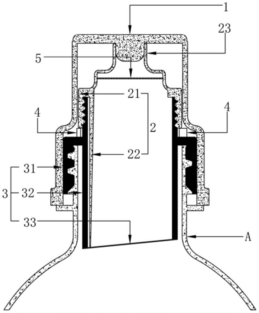
As shown in fig. 1-3, the bottle cap of the present invention specifically includes an upper cap body 1, a middle screw body 2 and a lower connecting cap 3. Even lid 3 down is its rampart I31 lower extreme inside wall of tubular structure and is provided with internal thread I31 a upper end lateral wall and is provided with external screw thread I31 b, and rampart 31I middle part is provided with proportioning bins 32, and proportioning bins 32 lower floor is provided with and separates shelves membrane 33, even lid 3 down connects with beverage bottle bottleneck A screw thread soon through internal thread I31 a.
The middle rotating body 2 is of a tubular structure, an internal thread II 21a is arranged on the inner side wall of the lower end of the annular wall II 21 of the middle rotating body, a rotary cutter 22 is arranged in a cavity of the annular wall II 21, the middle rotating body 2 is connected to an external thread I31 b of the lower connecting cover 3 in a rotating mode through the internal thread II 21a, and the upper cover body is arranged at an opening of the upper end face of the middle rotating body.
The specific application of the bottle cap according to the present invention will be further described below.
Referring to fig. 1-3, firstly, the upper cover body 1 is tightly connected to the upper end of the middle rotary body 2, then the external thread i 31b arranged at the upper end of the lower connecting cover 3 is screwed into the proper position in the internal thread ii 21a arranged at the lower end of the middle rotary body 2, then tea leaves or other flavoring agents are filled into the proportioning bin 32 arranged at the middle part of the middle rotary body 2, the lower bottom surface of the proportioning bin 32 is provided with a barrier film 33 for sealing the proportioning bin 3, and then the combination of the upper cover body 1, the middle rotary body 2 and the lower connecting cover 3 which are filled with the tea leaves or other flavoring agents is screwed on the external thread of the bottle mouth a of the beverage bottle through the internal thread i 31a arranged at the lower end of the lower connecting cover 3.
When the beverage is to be drunk, the middle rotary body 2 is further rotated downwards, the rotary cutter 22 is driven by the middle rotary body 2 to rotate downwards, the rotary cutter 22 rotates downwards to cut and stir the tea leaves or other flavoring agents in a semi-coagulated state while the partition film 33 is cut and broken, and the tea leaves or other flavoring agents fall into the beverage bottle to be fully fused with water, and then the upper cover body 1 is opened for drinking.
The connection mode of the upper cover body 1 and the middle rotator 2 of the bottle cap according to the first embodiment has the following two modes.
As shown in fig. 1-3, an external thread ii 21b is provided on an outer side wall of an upper end of a circumferential wall ii 21 of the middle rotating body 2, an internal thread iii 11a is provided on an inner side wall of the upper cover body 1, and the upper cover body 1 is screwed on the external thread ii 21b of the middle rotating body 2 through the internal thread iii 11.
As shown in fig. 4, the upper cover 1 is fastened to the top opening of the middle rotator 2.
Example two
As shown in fig. 5-7, the present invention relates to a bottle cap, which comprises an upper cap body 1, a middle rotary body 2 and a lower connecting cap 3.
Even lid 3 down is its rampart I31 lower extreme inside wall of tubular structure and is provided with internal thread I31 a upper end lateral wall and is provided with external screw thread I31 b, and rampart 31I middle part is provided with proportioning bins 32, and proportioning bins 32 lower floor is provided with and separates shelves membrane 33, even lid 3 down connects with beverage bottle bottleneck A screw thread soon through internal thread I31 a.
The middle rotating body 2 is of a tubular structure, an internal thread II 21a is arranged on the inner side wall of the lower end of the annular wall II 21 of the middle rotating body 2, a rotary cutter 22 is arranged in a cavity of the annular wall II 21, the middle rotating body 2 is connected to an external thread I31 b of the lower connecting cover 3 in a rotating mode through the internal thread II 21a, and the upper cover body 1 is arranged on the outer end face of the lower connecting cover 3.
The connection mode of the upper cover body 1 and the lower connecting cover 3 of the bottle cap described in the second embodiment has the following two modes.
As shown in fig. 5-7, the outer side wall of the middle portion of the annular wall i 31 of the lower connecting cover 3 is provided with an external thread iii 31c, the inner side wall of the upper cover body 1 is provided with an internal thread iii 11a, and the upper cover body 1 is screwed on the external thread iii 31c of the lower connecting cover 3 through the internal thread iii 11 a.
As shown in fig. 8-9, the upper cover body 1 is fastened to the outer side wall of the annular wall i 31 of the lower connecting cover 3.
For preventing the utility model relates to a bottle cap, its upper cover body 1 and well spiral body 2, upper cover body 1 and even lid 3 under with, well spiral body 2 and even lid 3 under with, even appear not hard up phenomenon after unexpected rotation after lid 3 and beverage bottle bottleneck A screwed connection under with, in above-mentioned embodiment one and embodiment two the bottle cap is still including easy-to-draw ring 4.
Specifically, as shown in fig. 1-3, in the first embodiment, the opening tab 4 is connected to the bottom end surface of the lower connecting cover 3, the middle rotating body 2, and the cover body 1.
Specifically, as shown in fig. 4, in the first embodiment, the opening tab 4 is connected and disposed on the bottom end surface of the lower connecting cover 3 and the middle rotating body 2.
Specifically, as shown in fig. 5-7, in the second embodiment, the opening tab 4 is connected to the bottom end surfaces of the middle rotator 2 and the lid body 1.
Specifically, as shown in fig. 8 and 9, in the second embodiment, the opening tab 4 is connected to the bottom end surface of the middle rotary body 2.
In the above-mentioned embodiment of the easy-open tab 4, when the upper lid 1, the middle rotator 2 or the lower connecting lid 3 needs to be rotated, the easy-open tab 4 connected to the bottom end surface of the upper lid 1, the middle rotator 2 or the lower connecting lid 3 is torn off, so that the upper lid 1, the middle rotator 2 or the lower connecting lid 3 can be freely rotated up and down.
In order to facilitate the convenience of the bottle cap when the bottle cap drinks liquid in the bottle body during use, in the first embodiment and the second embodiment, as shown in fig. 4 to 9, the upper opening of the middle rotary body 2 is provided with a suction port 23.
In order to further enhance the convenience of the knife point of the rotary cutter 21b arranged in the cavity of the middle rotary body 2 to cut the barrier film 33, in the first embodiment and the second embodiment, as shown in fig. 3, 7 and 9, the bottom end of the proportioning bin 32 is arranged in an inclined plane, and the knife point of the rotary cutter 21b corresponds to the lowest point of the inclined plane of the bottom of the proportioning bin 32. The rotary cutter 21b is more likely to cut the barrier film 33 provided on the bottom end surface of the storage bin 32 when the middle rotary body 2 is rotated downward.
For convenience, the utility model relates to a bottle cap which is convenient when the bottle cap is used for drinking liquid in the bottle body, and prevents residues of tea or other flavoring agents from entering the mouth of a drinker along with the liquid.
Specifically, as shown in fig. 2-4 and 6-9, the filter screen 5 is disposed at the upper opening of the tubular annular wall ii 21 of the middle rotating body 2 in the first and second embodiments. The filter screen 5 is used for separating the residues of tea leaves or other flavoring agents.
The above is the detailed introduction of the bottle cap provided by the embodiment of the present invention, and to the general technical personnel in the field, the idea of the embodiment of the present invention has a change part on the concrete implementation and the application range. In summary, the content of the present specification should not be understood as a limitation of the present invention, and any changes made according to the design concept of the present invention are all within the protection scope of the present invention.