Injection mold ejection mechanism capable of achieving rapid demolding
Technical Field
The utility model relates to an injection mold technical field specifically is an injection mold ejection mechanism that can fast demoulding.
Background
Injection molding, also known as injection molding, is a method of molding by injection and molding. The injection molding method has the advantages of high production speed, high efficiency, automation of operation, various colors, various shapes from simple to complex, small sizes, accurate product size, easy replacement of products, capability of forming products with complex shapes, suitability for the molding processing fields of mass production, products with complex shapes and the like; stirring the completely molten plastic material by a screw at a certain temperature, injecting the plastic material into a mold cavity by high pressure, and cooling and solidifying to obtain a molded product. The method is suitable for mass production of parts with complex shapes, and is one of important processing methods.
Injection molds are tools for producing plastic articles and are also tools for imparting complete structure and precise dimensions to plastic articles. The injection molding is a common processing method for mass production of some parts with complex shapes, and specifically refers to that materials which are heated and melted are injected into a mold cavity from high pressure, and after cooling and solidification, a formed product injection mold is obtained and consists of a movable mold and a fixed mold, wherein the movable mold is arranged on a movable mold plate of an injection molding machine, and the fixed mold is arranged on a fixed mold plate of the injection molding machine. And when the mold is opened, the movable mold is separated from the fixed mold so as to take out the plastic product.
After the product is formed, the product is taken out of the die conveniently, and the product needs to be demoulded by means of a specific ejection device, so that the product processing time is too long, and the production efficiency is reduced.
SUMMERY OF THE UTILITY MODEL
The to-be-solved technical problem of the utility model is to overcome current defect, provide an injection mold ejection mechanism that can fast demoulding to with the product drawing of patterns from the mould in solving above-mentioned technical background, lead to the time overlength of product processing, and then reduced production efficiency's shortcoming.
In order to achieve the above object, the utility model provides a following technical scheme: an injection mold ejection mechanism capable of realizing rapid demolding comprises a supporting component, a main demolding component, a secondary demolding component and a mold component arranged on the supporting component, wherein the main demolding component is connected with the secondary demolding component and is arranged on the mold component;
the die assembly comprises an upper die and a die bottom plate, the upper die and the die bottom plate are both arranged on the supporting assembly, and the upper die is positioned above the die bottom plate;
the main demoulding assembly comprises a mould base, an air cylinder and an output rod, wherein the mould base is of a cuboid structure and is arranged below the mould base plate; the cylinder is arranged in the mold base, and one end of the output rod arranged on the cylinder is movably arranged above the mold base in a penetrating way and is connected with the mold bottom plate;
the secondary demolding assembly comprises baffles, a rotating shaft and an adjusting rod, one sides of the four baffles are vertically arranged on the upper surface of the mold base and are connected with the mold base through the rotating shaft, and the four baffles are respectively positioned at positions close to four side surfaces of the mold base; one end of each adjusting rod is movably connected with the corresponding output rod, and the other end of each adjusting rod is movably connected with the corresponding four baffles.
Preferably, the supporting component comprises a lower base, an upper base and connecting rods, the upper base is arranged above the lower base, and the upper base is connected with the lower base through the two connecting rods; the two connecting rods are perpendicular to the upper base and the lower base.
Preferably, the mold base is arranged on the lower base and is positioned between the two connecting rods.
Preferably, the die base is provided with a limiting assembly, the limiting assembly comprises a supporting plate and a supporting column, the supporting plate is arranged on the die base through the supporting column, the supporting plate is positioned below the die bottom plate, and the supporting plate is provided with a through hole; the through hole is matched with the output rod.
Preferably, the upper die is arranged on the lower surface of the upper base and is positioned above the die bottom plate.
Preferably, every two baffles in opposite positions are connected through a telescopic rod, and a spring is sleeved on the telescopic rod.
Compared with the prior art, the utility model provides an injection mold ejection mechanism that can fast demoulding possesses following beneficial effect:
the utility model discloses a cooperation of main drawing of patterns subassembly and inferior drawing of patterns subassembly is convenient for carry out drawing of patterns to the product on the mould and handles, so that the product takes out from the mould, the time of product processing has been shortened, and the production efficiency is improved, it removes to be convenient for drive the output pole through the cylinder, it carries out the rebound to drive the mould bottom plate of being connected with the output pole, be convenient for ejecting to the product, so that the drawing of patterns, and be equipped with four baffles around the mould bottom plate, and be connected through the pivot between baffle and the mould base, the baffle of being convenient for rotates, it all is equipped with the regulation pole to keep off between every baffle and the output pole, and connect through adjusting the pole, when the output pole removes, be convenient for drive the baffle through adjusting the pole and rotate around the pivot, be convenient for the drawing of patterns of product, the drawing of patterns speed is improved, and production efficiency is improved.
Drawings
The accompanying drawings are included to provide a further understanding of the invention, and are incorporated in and constitute a part of this specification, illustrate embodiments of the invention, and together with the description, do not constitute a limitation of the invention, in which:
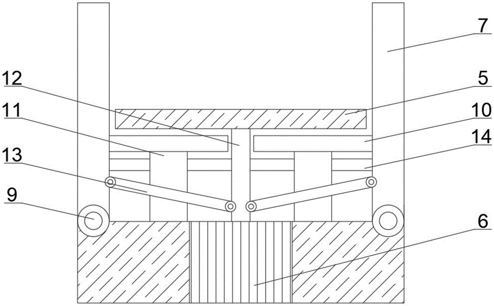
fig. 1 is a schematic structural view of a main demoulding assembly and a secondary demoulding assembly of the present invention;
fig. 2 is the utility model provides an injection mold ejection mechanism simple and easy structure schematic diagram that can fast demoulding.
In the figure: 1. the device comprises a lower base, 2, an upper base, 3, a die base, 4 connecting rods, 5, a die bottom plate, 6, a cylinder, 7, a baffle, 8, an upper die, 9, a rotating shaft, 10, a supporting plate, 11, a supporting column, 12, an output rod, 13, an adjusting rod, 14 and a telescopic rod.
Detailed Description
In order to make the technical means, the creation features, the achievement purposes and the functions of the present invention easy to understand, the present invention will be further explained below with reference to the following embodiments and the accompanying drawings, but the following embodiments are only preferred embodiments of the present invention, and not all embodiments are included. Based on the embodiments in the implementation, other embodiments obtained by those skilled in the art without any creative work belong to the protection scope of the present invention.
Referring to fig. 1-2, the utility model provides an injection mold ejection mechanism technical scheme that can demold fast: an injection mold ejection mechanism capable of realizing rapid demolding comprises a supporting component, a main demolding component, a secondary demolding component and a mold component arranged on the supporting component, wherein the main demolding component and the secondary demolding component are connected and are arranged on the mold component;
the mould assembly comprises an upper mould 8 and a mould bottom plate 5, the upper mould 8 and the mould bottom plate 5 are both arranged on the supporting assembly, and the upper mould 8 is positioned above the mould bottom plate (5);
the main demoulding assembly comprises a mould base 3, a cylinder 6 and an output rod 12, wherein the mould base 3 is of a cuboid structure, and the mould base 3 is arranged below the mould bottom plate 5; the cylinder 6 is arranged in the mold base 3, one end of an output rod 12 arranged on the cylinder 6 is movably arranged above the mold base 3 in a penetrating manner and connected with the mold bottom plate 5, so that the output rod 12 drives the mold bottom plate 5 to move through the cylinder 6, a product on the mold is ejected out, and the product is conveniently demoulded;
the secondary demoulding assembly comprises baffle plates 7, a rotating shaft 9 and an adjusting rod 13, wherein one sides of the four baffle plates 7 are vertically arranged on the upper surface of the mould base 3 and are connected with the mould base 3 through the rotating shaft 9, and the four baffle plates 7 are respectively positioned at positions close to four side surfaces of the mould base 3; one end of each of four adjusting rods 13 is movably connected with the output rod 12, and the other end of each of the four adjusting rods is movably connected with the four baffles 7.
The supporting component comprises a lower base 1, an upper base 2 and connecting rods 4, wherein the upper base 2 is arranged above the lower base 1, and the upper base 2 is connected with the lower base 1 through the two connecting rods 4; two connecting rods 4 are perpendicular to the upper base 2 and the lower base 1, so that the upper base 2 and the lower base 1 can be fixed conveniently through the connecting rods 4, and the upper base 2 and the lower base 1 can be placed to move.
The mold base 3 is arranged on the lower base 1 and is positioned between the two connecting rods 4.
A limiting assembly is arranged on the mold base 3 and comprises a supporting plate 10 and a supporting column 11, the supporting plate 10 is arranged on the mold base 3 through the supporting column 11, the supporting plate 10 is positioned below the mold bottom plate 5, and a through hole is formed in the supporting plate 10; the through hole is matched with the output rod 12, so that the output rod 12 can penetrate through the support plate 10 from the through hole.
The upper die 8 is arranged on the lower surface of the upper base 2 and is positioned above the die bottom plate 5.
All connect through telescopic link 14 between per two relative baffles 7 in position, the cover is equipped with the spring on the telescopic link 14, and telescopic link 14 is convenient for provide the effect of pulling force to baffle 7, is convenient for make baffle 7 stably resume the normal position.
The utility model discloses a theory of operation and use flow: firstly, between 8 and mould bottom plate 5 and baffle 7 through last mould, be convenient for mould plastics to the product, rethread cylinder 6 is convenient for drive output rod 12 and removes, drive the mould bottom plate 5 of being connected with output rod 12 and carry out the rebound, be convenient for ejecting to the product, so that the drawing of patterns, and be equipped with four baffles 7 around mould bottom plate 5, and be connected through pivot 9 between baffle 7 and the mould base, be convenient for baffle 7 rotates, and all be equipped with between every baffle 7 and the output rod 12 and adjust pole 13, and connect through adjusting pole 13, when output rod 12 removes, be convenient for drive baffle 7 through adjusting pole 13 and rotate around pivot 9, be convenient for the drawing of patterns of product, the drawing of patterns speed has been improved, and production efficiency is improved.
The foregoing shows and describes the general principles, essential features, and advantages of the invention. It should be understood by those skilled in the art that the present invention is not limited by the above embodiments, and the description in the above embodiments and the description is only preferred examples of the present invention, and is not intended to limit the present invention, and that the present invention can have various changes and modifications without departing from the spirit and scope of the present invention, and these changes and modifications all fall into the scope of the claimed invention. The scope of the invention is defined by the appended claims and equivalents thereof.