Hand abrasive belt adjusting mechanism
Technical Field
The utility model relates to an abrasive band machine technical field, concretely relates to use hand abrasive band adjustment mechanism in abrasive band machine.
Background
With the development of science and technology, people have higher and higher requirements on the taste of life. Among them, daily hardware is most widely used in life.
Therefore, in the process of machining daily hardware parts, some parts are often required to be subjected to grinding and polishing or wire drawing processing. The grinding and polishing are to process the surface of the workpiece to make the workpiece smooth and clean. The surface wire drawing treatment is a surface treatment means which forms lines on the surface of a workpiece through a grinding product and has a decorative effect. Because the texture of the metal material can be reflected by the surface wire drawing treatment, the surface wire drawing treatment is more and more popular among users and is more and more widely applied.
The belt sander is one of grinding and polishing machines. Like publication number "CN 206154051U", the name is "novel abrasive band machine", it includes frame, motor cabinet, motor, upper and lower adjustment mechanism, driving shaft and the symmetry sets up the action wheel subassembly at this driving shaft both ends, the driving shaft passes through the bearing assembly with following the fulcrum and sets up in the upper portion of frame and lower part position, the runner of going down on the driven shaft is connected with the action wheel subassembly of its corresponding position through the abrasive band, the motor passes through the motor cabinet and sets up in the back bottom of frame, upper and lower adjustment mechanism is located the front position of frame and can adjusts the position of motor. The driving wheel set comprises a supporting rod, a main wheel, an auxiliary wheel and a belt tensioning mechanism, wherein one end of the supporting rod is fixed on the side wall of the rack through a bearing seat on a bearing assembly, the auxiliary wheel is arranged at the other end of the supporting rod through the belt tensioning mechanism, and the end part of the driving shaft penetrates through a bearing on the bearing seat to form an installation part. When the abrasive belt is replaced, the operation is complex, a tool is needed to unscrew the bolt on the belt tensioning mechanism, after the bolt is unscrewed, the position of the belt tensioning mechanism on the supporting rod can be adjusted, the distance between the main wheel and the auxiliary wheel is shortened, and the abrasive belt can be completely loosened and disassembled; at this time, the abrasive belt can be taken up and a new abrasive belt can be installed; then the belt tensioning mechanism is restored to the position preset on the supporting rod and the bolt is locked; then, because the circumference of each abrasive belt is slightly different, the tensioning nut in the belt tensioning mechanism needs to be adjusted to achieve fine adjustment of the tensioning degree of the abrasive belt, the adjustment process needs to be operated after the abrasive belt is shut down, after the adjustment, the abrasive belt needs to be started to operate to polish to see whether the tensioning degree is suitable, otherwise, the abrasive belt needs to be shut down to adjust again, and the adjustment can be achieved by repeating for several times sometimes, so that the working efficiency is affected.
SUMMERY OF THE UTILITY MODEL
Not enough to the aforesaid, the utility model aims to provide a structural design is ingenious, reasonable, and the motor is built-in, and is dustproof effectual, and the abrasive band changes the convenience, adjusts the simple and easy hand abrasive band adjustment mechanism of partial operation.
In order to achieve the above purpose, the utility model provides a technical scheme is: a hand-operated abrasive belt adjusting mechanism comprises a rack, a motor, a rotating shaft, a driving wheel, an abrasive belt, a hand-operated abrasive belt adjusting mechanism, an auxiliary wheel adjusting mechanism, a bearing seat, an auxiliary wheel and a guide wheel, wherein the rotating shaft is horizontally arranged at the upper part of the rack through the bearing seat; the auxiliary wheel adjusting mechanism is arranged on the frame corresponding to the lower position of the driving wheel, and the auxiliary wheel is arranged on the auxiliary wheel adjusting mechanism and can adjust the deflection angle through the auxiliary wheel adjusting mechanism; the abrasive belt is wound around the driving wheel, the guide wheel and the auxiliary wheel.
As a preferred scheme of the utility model, the bearing frame includes pedestal and bearing, the radial increase of one end of pedestal forms the installation department, and the terminal surface middle part indent of this installation department forms the installation cavity, and the other end axial extension of this pedestal forms the portion of cup jointing, should cup joint the portion go up the axial be equipped with the shaft hole that the installation cavity is linked together, the bearing sets up in the installation cavity.
As a preferred scheme of the utility model, the protruding assembly portion that forms in the outer fringe position of installation department is equipped with the mounting hole in this assembly portion. The outline of the mounting part is circular. The outline of the assembly part is square. The angle position of the assembly part is provided with a convex rib extending towards the circle center direction of the installation part. The length of the sleeve joint part is 50-150 mm. Installation department and assembly portion and socket joint portion connection structure as an organic whole. The bearing is an outer spherical bearing.
As a preferred proposal of the utility model, the auxiliary wheel adjusting mechanism comprises a fixed seat, a movable frame, an adjusting screw rod and a locking screw rod, one end of the movable frame extends horizontally to form an adjusting part, the other end bends and extends for a certain distance to form a deflection part, the fixed seat is provided with an adjusting cavity, the adjusting part extends into the adjusting cavity, the middle part of the movable frame is hinged on the fixed seat, the adjusting part is provided with an adjusting screw hole matched with the adjusting screw rod, one side of the adjusting screw hole is a plane to form a locking plane, the upper position of the fixed seat corresponding to the adjusting screw hole and the locking plane is correspondingly provided with a through hole and a locking screw hole, the adjusting screw penetrates through the through hole and is screwed into the adjusting screw hole, the locking screw is screwed into the locking screw hole and penetrates out of the locking screw hole to be pressed on the locking plane, and the auxiliary wheel is arranged on the deflection part through the wheel shaft.
As a preferred scheme of the utility model, the lower end of the deflection part is provided with a shaft barrel for mounting the wheel shaft, the barrel wall of the shaft barrel is radially provided with a lock hole, and a screw which can radially extend into the lock hole is screwed in the lock hole; the fixing seat is provided with a mounting plate, and the mounting plate is provided with a mounting hole. And a deep groove ball bearing matched with the wheel shaft is arranged on the shaft hole of the guide wheel. The number of the deep groove ball bearings is two, and the deep groove ball bearings are located at openings at two ends of the shaft hole of the auxiliary wheel. And the outer side of the wheel shaft corresponding to the deep groove ball bearing is provided with an outer clamping groove, and an outer clamping ring is arranged on the outer clamping groove. The hole wall of the shaft hole of the auxiliary wheel is provided with an inner clamping groove corresponding to the inner side position of the deep groove ball bearing, and the inner clamping groove is provided with an inner clamping ring. The tail low surface of the adjusting part gradually inclines upwards.
As an optimized scheme of the utility model, hand abrasive band adjustment mechanism includes holder, support arm optical axis, axle shoulder piece, accommodate the lead screw, adjusting nut, lead screw bearing frame, slider and alignment jig, the one end of support arm optical axis is fixed on the holder, slider movable sleeve establishes on the support arm optical axis, the alignment jig sets up on the slider, the guide pulley sets up on the alignment jig through the installation axle, the axle shoulder piece sets up on the support arm optical axis, the lead screw bearing frame is fixed on the axle shoulder piece, accommodate the lead screw sets up on the lead screw bearing frame, and this accommodate the lead screw with the support arm optical axis parallels, adjusting nut sets up on the alignment jig, and with accommodate the lead screw looks adaptation.
As a preferred scheme of the utility model, the one end of holder is equipped with the axle sleeve, and the other end is equipped with the plug bush mutually perpendicular with the axial lead of this axle sleeve, be equipped with the crack groove on the mantle wall of axle sleeve, the bilateral symmetry in this crack groove is equipped with the locking block that enables the axle diameter of axle sleeve to reduce when folding, be equipped with the locating piece on the plug bush, be equipped with on this locating piece and radially run through its and plug bush lockhole, in the support arm optical axis inserted the plug bush, and the position that corresponds the lockhole was equipped with the screens, and the screw twists lockhole and roof pressure on the screens.
As an optimized scheme of the utility model, hand abrasive band adjustment mechanism still includes the direction subassembly, and this direction subassembly includes preceding clamp seat, back clamp seat and guide arm, preceding clamp seat and back clamp seat correspond the front and back position setting of slider and are in on the support arm optical axis, the both ends of guide arm are corresponding to be set up in the front, on the back clamp seat, and this guide arm with the support arm optical axis parallels, be equipped with the guide hole with this guide arm looks adaptation on the slider.
As an optimized scheme of the utility model, one side of preceding clamp seat be equipped with the pilot hole of guide arm looks adaptation, the opposite side be equipped with the hoop hole of support arm optical axis looks adaptation. The rear clamp seat is consistent with the front clamp seat in structure. And a guide sleeve matched with the guide rod is arranged on the guide hole of the sliding block. And a hand wheel is arranged at the tail end of the adjusting screw rod. The side wall of the adjusting frame is provided with an assembling sleeve matched with the mounting shaft, the sleeve wall matched with the assembling sleeve is radially provided with a lock hole, and a screw capable of radially extending into the lock hole is screwed into the lock hole. And a deep groove ball bearing matched with the mounting shaft is arranged on the wheel hole of the guide wheel. The number of the deep groove ball bearings is two, and the deep groove ball bearings are located at openings at two ends of the shaft hole of the auxiliary wheel. The outer side position that the installation axle corresponds deep groove ball bearing is equipped with outer draw-in groove, is equipped with outer snap ring on this outer draw-in groove. And the hole wall of the wheel hole of the guide wheel is provided with an inner clamping groove corresponding to the inner side of the deep groove ball bearing, and the inner clamping groove is provided with an inner clamping ring.
As an optimized proposal of the utility model, the top surface of the frame is provided with a tray.
As an optimized scheme of the utility model, the bearing frame is close to be equipped with the protection casing that covers this drive wheel on the position of drive wheel. The protection effect is good. Specifically, a sleeve body matched with the sleeve joint part of the bearing seat is arranged on one side of the protective cover, the sleeve body is sleeved on the sleeve joint part, and then the sleeve body is screwed in through a radial screw to achieve the purpose of locking and fixing.
As a preferred scheme of the utility model, the frame includes chassis, tilt frame and high screw rod, the chassis is fixed the inside bottom surface of frame, the one end of tilt frame articulates on the chassis, the other end be equipped with the trompil of high screw rod looks adaptation, the lower extreme of high screw rod articulates on the chassis, and the upper end is passed the trompil has been twisted high nut. The motor is installed on the tilting frame, the transmission assembly is preferably a belt transmission assembly, an included angle between the tilting frame and the underframe is adjusted by screwing the height nut, and then the height position of the motor is adjusted to achieve the function of adjusting the tightness of the belt.
The utility model has the advantages that: the utility model discloses structural design is ingenious, reasonable, can accelerate the operating speed who changes the abrasive band greatly. When the abrasive belt needs to be replaced, the hand wheel is screwed, the adjusting screw rod is driven to rotate, the rotating motion is converted into linear motion through the matching of the adjusting nut and the adjusting screw rod, the sliding block is correspondingly pulled to move backwards, the guide wheel is driven to move backwards through the adjusting frame, the purpose of loosening the abrasive belt is achieved, and convenience is brought to the abrasive belt replacing process. After the upper abrasive belt is replaced, the hand wheel is reversed, so that the guide wheel can be pushed to move forwards through the adjusting frame, and the purpose of tightening the abrasive belt is achieved; when the elasticity degree of abrasive band need be adjusted, only need corotation or anti-move twist move the hand wheel can, when the adjustment, need not to stop moreover, can polish through real-time operation and look over whether the tensioning degree is fit for, whole operation process is simple, quick, and labour saving and time saving effectively promotes work efficiency.
The present invention will be further explained with reference to the drawings and the embodiments.
Drawings
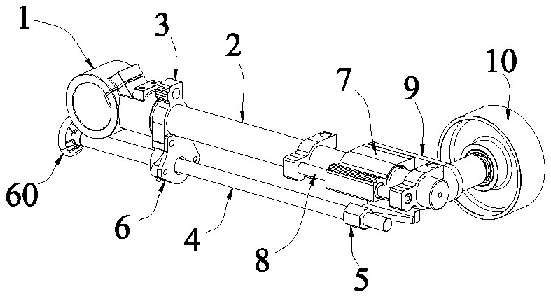
Fig. 1 is a schematic perspective view of the present invention.
Fig. 2 is an exploded schematic view of the present invention.
Fig. 3 is a schematic view of the present invention in a partial cross-sectional structure.
Fig. 4 is a schematic structural view of the present invention during installation and use.
Detailed Description
In an embodiment, referring to fig. 1 to 3, the hand-cranking abrasive belt adjusting mechanism provided in this embodiment includes a holder 1, a support arm optical axis 2, a shoulder block 3, an adjusting screw 4, an adjusting nut 5, a screw shaft bearing block 6, a slider 7, a guiding assembly 8, and an adjusting frame 9, where one end of the support arm optical axis 2 is fixed on the holder 1, the slider 7 is movably sleeved on the support arm optical axis 2, the adjusting frame 9 is disposed on the slider 7, a guide wheel 10 is disposed on the adjusting frame 9 through an installation shaft 20, the shoulder block 3 is disposed on the support arm optical axis 2, the screw shaft bearing block 6 is fixed on the shoulder block 3, the adjusting screw 4 is disposed on the screw shaft bearing block 6, and the adjusting screw 4 is parallel to the optical axis 2, and the adjusting nut 5 is disposed on the adjusting frame 9 and is adapted to the adjusting screw 4.
Specifically, one end of the clamp holder 1 is provided with a shaft sleeve 11, the other end of the clamp holder is provided with an inserting sleeve 12 perpendicular to the axial lead of the shaft sleeve 11, the sleeve wall of the shaft sleeve 11 is provided with a split groove, two sides of the split groove are symmetrically provided with locking blocks 13 capable of enabling the sleeve diameter of the shaft sleeve 11 to be reduced to clamp the sleeved part when being folded, through holes are formed in the two locking blocks 13, a bolt penetrates through the through holes and is screwed with a nut, and the two locking blocks 13 are forced to be folded through the locking nut.
The positioning block 14 is arranged on the plug bush 12, the positioning block 14 is provided with a lock hole which can radially penetrate through the positioning block 14 and the plug bush 12, the support arm optical axis 2 is inserted into the plug bush 12, a position corresponding to the lock hole is provided with a clamping position 21, a screw is screwed into the lock hole and is pressed on the clamping position 21, and the purpose of locking and preventing the support arm optical axis 2 from rotating is achieved.
Guide assembly 8 includes preceding clamp seat 81, back clamp seat 82 and guide arm 83, preceding clamp seat 81 and back clamp seat 82 correspond the front and back position setting of slider 7 and are in on the support arm optical axis 2, the both ends of guide arm 83 are corresponding to be set up in the front on clamp seat 81, back clamp seat 82, and this guide arm 83 with support arm optical axis 2 parallels, be equipped with the guide hole with this guide arm 83 looks adaptation on the slider 7. The sliding of the sliding block 7 is guided through the guide assembly 8, so that the running stability is improved, and the working stability is good.
One side of the front clamp seat 81 is provided with an assembly hole matched with the guide rod 83, and the other side is provided with a clamp hole matched with the support arm optical axis 2. The screw on the hoop hole is screwed, so that the aperture of the hoop hole is reduced to tightly hold the support arm optical axis 2, and the purpose of fixing is realized. The rear clip seat 82 is identical in structure to the front clip seat 81.
The guide hole of the sliding block 7 is provided with a guide sleeve matched with the guide rod 83, so that the sliding is smooth, and the service life is prolonged. The end of the adjusting screw rod 4 is provided with a hand wheel 60, which brings convenience to the rotation of the adjusting screw rod 4. In addition, an adjusting motor 2 for driving the adjusting screw rod 4 to rotate can also be additionally arranged. The side wall of the adjusting bracket 9 is provided with an assembling sleeve 91 matched with the mounting shaft 20, the sleeve wall of the assembling sleeve 91 is radially provided with a lock hole, a screw which can radially extend into the lock hole is screwed into the lock hole, and the mounting shaft 20 is pressed tightly through the screw, so that the purpose of assembling and fixing is realized.
In order to prolong the service life, a deep groove ball bearing 30 matched with the mounting shaft 20 is arranged on the wheel hole of the guide wheel 10. Preferably, the number of the deep groove ball bearings 30 is two, and the two deep groove ball bearings are located at openings at two ends of the shaft hole of the guide wheel 10. And an outer clamping groove is arranged at the outer side position of the mounting shaft 20 corresponding to the deep groove ball bearing 30, and an outer clamping ring 40 is arranged on the outer clamping groove. An inner clamping groove 79 is formed in the hole wall of the wheel hole of the guide wheel 10 corresponding to the inner side of the deep groove ball bearing 30, and an inner clamping ring 50 is arranged on the inner clamping groove 79.
When the abrasive belt 70 needs to be replaced, referring to fig. 4, the hand wheel 60 is screwed to drive the adjusting screw rod 4 to rotate, the adjusting nut 5 is matched with the adjusting screw rod 4 to convert the rotation motion into the linear motion, the sliding block 7 is pulled to move backwards, and the adjusting frame 9 drives the guide wheel 10 to move backwards, so that the purpose of loosening the abrasive belt 70 is achieved, and convenience is brought to the replacing process of the abrasive belt 70. After the upper abrasive belt 70 is replaced, the hand wheel 60 is reversed, the guide wheel 10 can be pushed to move forwards through the adjusting frame 9, the purpose of tightening the abrasive belt 70 is achieved, the tightness degree of the abrasive belt 70 can be adjusted by correspondingly screwing the hand wheel 60, and different grinding requirements are met. The whole operation process is simple and quick, and the working efficiency is high.
Variations and modifications to the above-described embodiments may occur to those skilled in the art, in light of the above teachings and teachings. Therefore, the present invention is not limited to the specific embodiments disclosed and described above, and some modifications and changes to the present invention should fall within the protection scope of the claims of the present invention. In addition, although specific terms are used herein, they are used for convenience of description and are not intended to limit the present invention, and other mechanisms similar or identical to the specific terms are also within the scope of the present invention.