Industrial equipment drilling machine convenient to adjust
Technical Field
The utility model belongs to the technical field of the drilling machine, concretely relates to industrial equipment drilling machine convenient to adjust.
Background
The drilling machine is a machine tool which mainly uses a drill bit to process holes on a workpiece, usually, the drill bit rotates to move mainly, the drill bit moves axially to move in a feeding mode, the drilling machine is simple in structure, machining precision is relatively low, through holes and blind holes can be drilled, special cutters can be replaced, expanding, spot facing and reaming or tapping and the like can be carried out, the workpiece is fixed in the machining process, the cutters move, the centers of the cutters are aligned with the center of the hole, the cutters rotate, and the drilling machine is characterized in that the workpiece is fixed and the cutters rotate.
Drilling machine on the existing market often brings inconvenience to the drilling of target object because the drilling machine is difficult to control the drill bit and adjust when drilling to spare part, has increased staff's intensity of labour, and the high inconvenient regulation that also is not convenient to placing the platform influences the staff and uses.
SUMMERY OF THE UTILITY MODEL
To solve the problems set forth in the background art described above. The utility model provides an industrial equipment drilling machine convenient to adjust, it has solved technical problem such as work efficiency that inconvenient staff operated, influenced drilling.
In order to achieve the above object, the utility model provides a following technical scheme: the utility model provides an industrial equipment drilling machine convenient to adjust, includes the bottom plate, two support columns of top fixedly connected with of bottom plate, two the top fixedly connected with casing of support column, two first motors of top fixedly connected with of bottom plate, two the equal fixedly connected with driving gear of output shaft of first motor, two the surface of driving gear all meshes has driven gear, two equal first pivot of fixedly connected with in the driven gear, wear to be equipped with two second bearings in the casing, two the first lead screw of second bearing fixedly connected with is all passed on the top of first pivot, two the equal threaded connection in surface of first lead screw has first thread bush, two the platform is placed to the fixed surface of first thread bush is connected with.
The drill bit is characterized in that a second motor is fixedly connected in the shell, a second lead screw is fixedly connected to an output shaft of the second motor, a second thread sleeve is connected to the surface of the second lead screw in a threaded manner, a third motor is fixedly connected to the bottom side of the second thread sleeve, and a drill bit is fixedly connected to an output shaft of the third motor.
As a further aspect of the present invention: the top ends of the two first screw rods are fixedly connected with a second rotating shaft, the surfaces of the two second rotating shafts are rotatably connected with third bearings, the top ends of the two third bearings are fixedly connected with supporting blocks, and the two separated ends of the supporting blocks are fixedly connected in the shell.
As a further aspect of the present invention: two the surface of first pivot all rotates and is connected with first bearing, two the equal fixed connection in bottom of first bearing is on the bottom plate, two first spouts have been seted up in the casing, the equal sliding connection in first spout in both ends of placing the platform.
As a further aspect of the present invention: one end fixedly connected with third pivot of second lead screw, the surface of third pivot all rotates and is connected with the fourth bearing, the one end fixed connection of fourth bearing is in the casing.
As a further aspect of the present invention: a second sliding groove is formed in the shell, a sliding block is connected in the second sliding groove in a sliding mode, and the bottom end of the sliding block is fixedly connected to the second threaded sleeve.
As a further aspect of the present invention: two fixed frames of top fixedly connected with of placing the platform, two equal fixedly connected with spring in the fixed frame, two the equal fixedly connected with splint in bottom of spring.
As a further aspect of the present invention: the front end of the shell is rotatably connected with a shell door through a hinge, the surface of the shell door is fixedly connected with a handle, and a coded lock is arranged in the shell door.
As a further aspect of the present invention: the side fixedly connected with button switch of casing, button switch passes through wire electric connection with first motor, second motor and third motor respectively.
Compared with the prior art, the beneficial effects of the utility model are that:
1. this industrial equipment drilling machine convenient to adjust through setting up first motor, driving gear and driven gear, rotates through the output shaft of first motor and drives the driving gear and rotate to drive driven gear and rotate, then drive first lead screw and rotate and can drive and place the platform upwards slip and the lapse in first spout, be convenient for adjust the height of placing the platform, reduced staff's intensity of labour.
2. This industrial equipment drilling machine convenient to adjust through setting up second motor, second lead screw and second thread bush, rotates through the output shaft of second motor and drives the second lead screw and rotate, can drive the third motor and remove left and right under the gliding cooperation of slider in the second spout, can control the drill bit and adjust, has improved the work efficiency of drilling.
3. This industrial equipment drilling machine convenient to adjust through setting up fixed frame, spring and splint, drives splint through spare part extrusion splint and removes to make splint extrusion spring, can fix spare part in splint under the effect of the elasticity of spring, fixed effectual prevents that spare part from taking place to remove at the in-process of drilling.
Drawings
The accompanying drawings are included to provide a further understanding of the invention, and are incorporated in and constitute a part of this specification, illustrate embodiments of the invention, and together with the description serve to explain the invention and not to limit the invention. In the drawings:
fig. 1 is a schematic front view of a cross-sectional structure of the present invention;
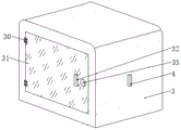
fig. 2 is a schematic perspective view of the housing of the present invention;
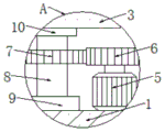
FIG. 3 is an enlarged schematic view of the structure of FIG. 1;
in the figure: 1. a base plate; 2. a support pillar; 3. a housing; 4. a push button switch; 5. a first motor; 6. a driving gear; 7. a driven gear; 8. a first rotating shaft; 9. a first bearing; 10. a second bearing; 11. a first lead screw; 12. a first threaded sleeve; 13. a first chute; 14. a placing table; 15. a second rotating shaft; 16. a third bearing; 17. a support block; 18. a second motor; 19. a second lead screw; 20. a second threaded sleeve; 21. a second chute; 22. a slider; 23. a third rotating shaft; 24. a fourth bearing; 25. a third motor; 26. a drill bit; 27. a fixing frame; 28. a spring; 29. a splint; 30. a hinge; 31. a shell door; 32. a handle; 33. a combination lock.
Detailed Description
The technical solutions in the embodiments of the present invention will be described clearly and completely with reference to the accompanying drawings in the embodiments of the present invention, and it is obvious that the described embodiments are only some embodiments of the present invention, not all embodiments. Based on the embodiments in the present invention, all other embodiments obtained by a person skilled in the art without creative work belong to the protection scope of the present invention.
Examples
Referring to fig. 1-3, the present invention provides the following technical solutions: an industrial equipment drilling machine convenient to adjust comprises a bottom plate 1, wherein the top end of the bottom plate 1 is fixedly connected with two support columns 2, the top ends of the two support columns 2 are fixedly connected with a shell 3, the top end of the bottom plate 1 is fixedly connected with two first motors 5, output shafts of the two first motors 5 are both fixedly connected with driving gears 6, the surfaces of the two driving gears 6 are both meshed with driven gears 7, first rotating shafts 8 are both fixedly connected in the two driven gears 7, two second bearings 10 penetrate through the shell 3, the top ends of the two first rotating shafts 8 both penetrate through the second bearings 10 and are fixedly connected with first lead screws 11, the surfaces of the two first lead screws 11 are both in threaded connection with first thread sleeves 12, the surfaces of the two first thread sleeves 12 are fixedly connected with a placing table 14, the driving gears 6 are driven to rotate through the rotation of the output shafts of the first motors 5, so as to drive the driven gears 7 to rotate, then drive first lead screw 11 and rotate and can drive and place platform 14 upwards slip and lapse in first spout 13, be convenient for adjust the height of placing platform 14, staff's intensity of labour has been reduced, the equal fixedly connected with second pivot 15 in top of two first lead screws 11, the surface of two second pivots 15 all rotates and is connected with third bearing 16, the equal fixedly connected with supporting shoe 17 in top of two third bearings 16, the equal fixed connection in end that leaves mutually of two supporting shoes 17 is in casing 3.
Fixedly connected with second motor 18 in casing 3, fixedly connected with second lead screw 19 on the output shaft of second motor 18, the surperficial threaded connection of second lead screw 19 has second thread bush 20, the bottom side fixedly connected with third motor 25 of second thread bush 20, fixedly connected with drill bit 26 on the output shaft of third motor 25, the output shaft through second motor 18 rotates and drives second lead screw 19 and rotate, can drive third motor 25 and remove left side and right side under the gliding cooperation of slider 22 in second spout 21, can control drill bit 26, the work efficiency of drilling has been improved, the one end fixedly connected with third pivot 23 of second lead screw 19, the surface of third pivot 23 all rotates and is connected with fourth bearing 24, the one end fixed connection of fourth bearing 24 is in casing 3.
Specifically, the surface of two first rotating shafts 8 is all rotated and is connected with first bearing 9, the equal fixed connection in bottom of two first bearings 9 is on bottom plate 1, has seted up two first spouts 13 in the casing 3, and the equal sliding connection in first spout 13 in both ends of placing platform 14 has seted up second spout 21 in the casing 3, and sliding connection has slider 22 in the second spout 21, and slider 22's bottom fixed connection is on second thread bush 20.
Specifically, place two fixed frames 27 of top fixedly connected with of platform 14, equal fixedly connected with spring 28 in two fixed frames 27, the equal fixedly connected with splint 29 in bottom of two springs 28 drives splint 29 through spare part extrusion splint 29 and removes to make splint 29 extrusion spring 28, can fix spare part in splint 29 under the effect of the elastic force of spring 28, fixed effectual prevents that the spare part from taking place to remove at the in-process of drilling.
Specifically, the front end of the housing 3 is rotatably connected with a housing door 31 through a hinge 30, a handle 32 is fixedly connected to the surface of the housing door 31, and a coded lock 33 is arranged in the housing door 31.
Specifically, the side surface of the housing 3 is fixedly connected with the button switch 4, and the button switch 4 is electrically connected with the first motor 5, the second motor 18 and the third motor 25 through wires.
The utility model discloses a theory of operation does:
s1, when in use, a worker inputs a password, unlocks the password lock 33, pulls the handle 32, drives the shell door 31 to rotate under the rotation coordination of the hinge 30, so as to open the shell 3, then places the component on the placing table 14, presses the clamping plate 29 by the component, drives the clamping plate 29 to move, enables the clamping plate 29 to press the spring 28, and fixes the component in the clamping plate 29 under the action of the elastic force of the spring 28;
s2, secondly, the worker clicks the button switch 4, the second motor 18 starts to work, the output shaft of the second motor 18 rotates to drive the second screw rod 19 to rotate, the second threaded sleeve 20 is driven to move leftwards under the matching of the sliding block 22 in the second sliding groove 21, so that the third motor 25 is driven to move leftwards, then the drill bit 26 is driven to move leftwards, after the drill bit moves to a proper position, the button switch 4 is clicked, and the second motor 18 stops working;
s3, then, the staff clicks the button switch 4, the third motor 25 starts to work, the output shaft of the third motor 25 rotates to drive the drill bit 26 to rotate, simultaneously, the output shafts of the two second motors 18 rotate to drive the driving gear 6 to rotate, thereby driving the two driven gears 7 to rotate to drive the first rotating shaft 8 to rotate, then driving the two first lead screws 11 to rotate, finally driving the placing table 14 to slide upwards in the first sliding groove 13, and the component moves upwards along with the placing table 14, thereby drilling the component.
While embodiments of the present invention have been shown and described, it is to be understood that the above embodiments are exemplary and should not be construed as limiting the present invention, and that modifications, alterations, substitutions and variations may be made to the above embodiments by those of ordinary skill in the art without departing from the scope of the present invention.