CN213968712U - Stamping device is used in cutting piece production convenient to clearance - Google Patents
Stamping device is used in cutting piece production convenient to clearance Download PDFInfo
- Publication number
- CN213968712U CN213968712U CN202022519976.3U CN202022519976U CN213968712U CN 213968712 U CN213968712 U CN 213968712U CN 202022519976 U CN202022519976 U CN 202022519976U CN 213968712 U CN213968712 U CN 213968712U
- Authority
- CN
- China
- Prior art keywords
- jet
- stamping device
- propelled
- fixedly connected
- protecting frame
- Prior art date
- Legal status (The legal status is an assumption and is not a legal conclusion. Google has not performed a legal analysis and makes no representation as to the accuracy of the status listed.)
- Active
Links
Images


Landscapes
- Crushing And Pulverization Processes (AREA)
Abstract
The utility model discloses a cutting piece production stamping device convenient to clearance, including the stamping device body, the right side of stamping device body is provided with the air pump, the left side intercommunication of air pump has jet-propelled pipe, the one end intercommunication that the air pump was kept away from to jet-propelled pipe has jet-propelled rifle, the fixed surface of jet-propelled rifle is connected with the protecting frame, the bottom fixedly connected with workstation of protecting frame, the left side intercommunication of protecting frame has the tuber pipe, the one end intercommunication that the protecting frame was kept away from to the tuber pipe has the input of fan, the output intercommunication of fan has the dump bin, the dump bin is located the left side of stamping device body. The utility model discloses a set up air pump, jet-propelled pipe and jet-propelled rifle and blow up the waste material on workstation surface, the fan begins to operate simultaneously, inhales the waste material that blows up the workstation surface to the dump bin in through the tuber pipe. The utility model provides a current stamping device rely on artifical manual the clearance, have the problem of potential safety hazard.
Description
Technical Field
The utility model relates to a punching press technical field specifically is a stamping device is used in cutting piece production convenient to clearance.
Background
The stamping device can be used to punch the raw materials in the production process of the cutting blade, the raw materials and the surface of the workbench are easy to adhere to scraps in the punching process, the scraps need to be cleaned, the existing stamping device is manually cleaned by manpower, and potential safety hazards exist.
SUMMERY OF THE UTILITY MODEL
For solving the problem that provides in the above-mentioned background art, the utility model aims to provide a cutting piece production stamping device convenient to clearance possesses the advantage of the clearance of being convenient for, has solved current stamping device and has relied on artifical manual the clearing up, has the problem of potential safety hazard.
The utility model provides a following technical scheme: the utility model provides a stamping device is used in cutting piece production convenient to clearance, includes the stamping device body, the right side of stamping device body is provided with the air pump, the left side intercommunication of air pump has jet-propelled pipe, the one end intercommunication that the air pump was kept away from to jet-propelled pipe has jet-propelled gun, jet-propelled gun's fixed surface is connected with the protecting frame, the bottom fixedly connected with workstation of protecting frame, the left side intercommunication of protecting frame has the tuber pipe, the one end intercommunication that the protecting frame was kept away from to the tuber pipe has the input of fan, the output intercommunication of fan has the dump bin, the dump bin is located the left side of stamping device body, the inside of protecting frame is provided with scrapes the material mechanism.
The scraping mechanism comprises a long plate arranged inside the protective frame, the bottom of the long plate is fixedly connected with a scraper, sliding blocks are fixedly connected to the two sides of the long plate, sliding grooves matched with the sliding blocks to use are formed in the two sides of the inner wall of the protective frame, and the sliding blocks are connected with the sliding grooves in a sliding mode.
The front side fixedly connected with fixed block of workstation, the top of fixed block is provided with the connecting plate, the rear side of connecting plate and the front side contact of workstation, the fixed slot that the cooperation fixed block used is seted up to the bottom of connecting plate, the dirty silo has been seted up at the top of connecting plate.
The drawer is arranged at the bottom inside the waste bin, a handle is fixedly connected to the front side of the drawer, and anti-skid grains are arranged on the surface of the handle.
The front side and the rear side of the inner wall of the sliding groove are fixedly connected with limiting pads, and the limiting pads are made of rubber.
The material of scraper blade is rubber, the surface of long board is provided with anti-skidding line.
The utility model has the advantages as follows:
1. the utility model discloses a set up air pump, jet-propelled pipe and jet-propelled rifle and blow up the waste material on workstation surface, the fan begins to operate simultaneously, inhales to the dump bin through the waste material that the tuber pipe was blown up the workstation surface in, has solved current stamping device and has relied on artifical manual the clearance, has the problem of potential safety hazard.
2. The utility model discloses a set up the scraper blade, can clear up great sweeps, improved stamping device's practicality.
3. The utility model discloses a set up the dirty tank, can collect the waste material on workstation surface, convenient to use person clears up the waste material, has improved the practicality of scraping the material mechanism.
4. The utility model discloses a set up the drawer, can convenient to use person clear up the waste material, improved the practicality of dump bin, through setting up the handle, can convenient to use person remove the drawer, improved the practicality of drawer.
5. The utility model discloses a set up spacing pad, can prevent slider and spout bump, improved the life of slider.
6. The utility model discloses a material that sets up the scraper blade is rubber, can prevent scraper blade fish tail workstation, has improved the life of workstation.
Drawings
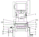
FIG. 1 is a schematic structural view of the present invention;
FIG. 2 is a schematic bottom view of the connecting plate of the present invention;
FIG. 3 is a schematic top view of the connection plate of the present invention;
FIG. 4 is a right-side view of the spacing pad of the present invention;
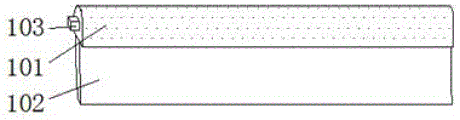
FIG. 5 is a schematic front view of the scraping mechanism of the present invention;
fig. 6 is a schematic view of the three-dimensional structure of the scraper blade of the present invention.
In the figure: 1. a stamping device body; 2. an air pump; 3. a gas ejector tube; 4. an air gun; 5. a protective frame; 6. a work table; 7. an air duct; 8. a fan; 9. a waste bin; 10. a scraping mechanism; 101. a long plate; 102. a squeegee; 103. a slider; 104. a chute; 11. a fixed block; 12. a connecting plate; 13. fixing grooves; 14. a waste chute; 15. a drawer; 16. a handle; 17. a limiting pad.
Detailed Description
The technical solution in the embodiments of the present invention will be clearly and completely described below with reference to the accompanying drawings in the embodiments of the present invention.
As shown in fig. 1 to 6, the utility model discloses a right side at stamping device body 1 is provided with air pump 2, the left side intercommunication of air pump 2 has jet-propelled pipe 3, the one end intercommunication that air pump 2 was kept away from to jet-propelled pipe 3 has jet-propelled gun 4, the fixed surface of jet-propelled gun 4 is connected with protecting frame 5, protecting frame 5's bottom fixedly connected with workstation 6, protecting frame 5's left side intercommunication has tuber pipe 7, the one end intercommunication that protecting frame 5 was kept away from to tuber pipe 7 has the input of fan 8, fan 8's output intercommunication has dump bin 9, dump bin 9 is located stamping device body 1's left side, protecting frame 5's inside is provided with scrapes material mechanism 10.
Referring to fig. 5, the scraping mechanism 10 includes a long plate 101 disposed inside the protection frame 5, a scraping plate 102 fixedly connected to the bottom of the long plate 101, sliders 103 fixedly connected to both sides of the long plate 101, sliding grooves 104 disposed on both sides of the inner wall of the protection frame 5 and used in cooperation with the sliders 103, and the sliders 103 slidably connected to the sliding grooves 104.
This embodiment can clear up great sweeps through setting up scraper blade 102, has improved stamping device's practicality.
Referring to fig. 1, a fixing block 11 is fixedly connected to the front side of the workbench 6, a connecting plate 12 is disposed on the top of the fixing block 11, the rear side of the connecting plate 12 contacts with the front side of the workbench 6, a fixing groove 13 matched with the fixing block 11 for use is disposed at the bottom of the connecting plate 12, and a waste chute 14 is disposed at the top of the connecting plate 12.
This embodiment can collect the waste material on workstation 6 surface through setting up waste material groove 14, and the person of facilitating the use clears up the waste material, has improved the practicality of scraping mechanism 10.
Referring to fig. 1, a drawer 15 is arranged at the bottom inside the waste bin 9, a handle 16 is fixedly connected to the front side of the drawer 15, and anti-skid lines are arranged on the surface of the handle 16.
This embodiment can convenient to use person clear up the waste material through setting up drawer 15, has improved the practicality of dump bin 9, through setting up handle 16, can convenient to use person remove drawer 15, has improved drawer 15's practicality.
Referring to fig. 4, the front side and the rear side of the inner wall of the sliding groove 104 are both fixedly connected with a limiting pad 17, and the limiting pad 17 is made of rubber.
This embodiment can prevent slider 103 and spout 104 from colliding through setting up spacing pad 17, has improved slider 103's life.
Referring to fig. 5, the material of the scraper 102 is rubber, and the surface of the long plate 101 is provided with anti-slip threads.
In the embodiment, the scraper 102 is made of rubber, so that the scraper 102 can be prevented from scratching the workbench 6, and the service life of the workbench 6 is prolonged.
The utility model discloses an air pump 2 blows the waste material on 6 surfaces of workstation through jet-propelled pipe 3 and jet-propelled gun 4, and fan 8 begins to operate simultaneously, inhales to dump bin 9 through the waste material that tuber pipe 7 was blown the workstation 6 surfaces to reach the effect of the clearance of being convenient for, when the great waste material appears on 6 surfaces of workstation, spur long slab 101 forward, long slab 101 drives scraper blade 102 and moves forward, can be with great waste material clearance.
Claims (6)
1. The utility model provides a cutting piece production stamping device convenient to clearance, includes stamping device body (1), its characterized in that: the right side of stamping device body (1) is provided with air pump (2), the left side intercommunication of air pump (2) has jet-propelled pipe (3), the one end intercommunication that air pump (2) were kept away from in jet-propelled pipe (3) has jet-propelled gun (4), the fixed surface of jet-propelled gun (4) is connected with protecting frame (5), the bottom fixedly connected with workstation (6) of protecting frame (5), the left side intercommunication of protecting frame (5) has tuber pipe (7), the one end intercommunication that protecting frame (5) were kept away from in tuber pipe (7) has the input of fan (8), the output intercommunication of fan (8) has dump bin (9), dump bin (9) are located the left side of stamping device body (1), the inside of protecting frame (5) is provided with scrapes material mechanism (10).
2. The punching device for producing the cutting blade convenient to clean as claimed in claim 1, wherein: scraping mechanism (10) is including setting up long board (101) in protection frame (5) inside, the bottom fixedly connected with scraper blade (102) of long board (101), the equal fixedly connected with slider (103) in both sides of long board (101), spout (104) that cooperation slider (103) used are all seted up to the both sides of protection frame (5) inner wall, slider (103) and spout (104) sliding connection.
3. The punching device for producing the cutting blade convenient to clean as claimed in claim 2, wherein: the front side fixedly connected with fixed block (11) of workstation (6), the top of fixed block (11) is provided with connecting plate (12), the rear side of connecting plate (12) contacts with the front side of workstation (6), fixed slot (13) that cooperation fixed block (11) used are seted up to the bottom of connecting plate (12), dirty tank (14) have been seted up at the top of connecting plate (12).
4. The punching device for producing the cutting blade convenient to clean as claimed in claim 3, wherein: the novel anti-skid garbage can is characterized in that a drawer (15) is arranged at the bottom inside the garbage can (9), a handle (16) is fixedly connected to the front side of the drawer (15), and anti-skid grains are arranged on the surface of the handle (16).
5. The punching device for producing the cutting blade convenient to clean as claimed in claim 4, wherein: the front side and the rear side of the inner wall of the sliding groove (104) are fixedly connected with limiting pads (17).
6. The punching device for producing the cutting blade convenient to clean as claimed in claim 5, wherein: the surface of the long plate (101) is provided with anti-skid grains.
Priority Applications (1)
| Application Number | Priority Date | Filing Date | Title |
|---|---|---|---|
| CN202022519976.3U CN213968712U (en) | 2020-11-04 | 2020-11-04 | Stamping device is used in cutting piece production convenient to clearance |
Applications Claiming Priority (1)
| Application Number | Priority Date | Filing Date | Title |
|---|---|---|---|
| CN202022519976.3U CN213968712U (en) | 2020-11-04 | 2020-11-04 | Stamping device is used in cutting piece production convenient to clearance |
Publications (1)
| Publication Number | Publication Date |
|---|---|
| CN213968712U true CN213968712U (en) | 2021-08-17 |
Family
ID=77260933
Family Applications (1)
| Application Number | Title | Priority Date | Filing Date |
|---|---|---|---|
| CN202022519976.3U Active CN213968712U (en) | 2020-11-04 | 2020-11-04 | Stamping device is used in cutting piece production convenient to clearance |
Country Status (1)
| Country | Link |
|---|---|
| CN (1) | CN213968712U (en) |
Cited By (1)
| Publication number | Priority date | Publication date | Assignee | Title |
|---|---|---|---|---|
| CN114406068A (en) * | 2021-12-27 | 2022-04-29 | 江苏哈工药机科技股份有限公司 | Electromechanical integrated stamping equipment |
-
2020
- 2020-11-04 CN CN202022519976.3U patent/CN213968712U/en active Active
Cited By (1)
| Publication number | Priority date | Publication date | Assignee | Title |
|---|---|---|---|---|
| CN114406068A (en) * | 2021-12-27 | 2022-04-29 | 江苏哈工药机科技股份有限公司 | Electromechanical integrated stamping equipment |
Similar Documents
| Publication | Publication Date | Title |
|---|---|---|
| CN207839715U (en) | A kind of automobile die decompressor | |
| CN204770303U (en) | Stamping die's clout recovery unit | |
| CN110605411A (en) | Scrap cleaning equipment for hardware machining | |
| CN106311679B (en) | A kind of environmentally friendly dedusting mechanism of plate conveying | |
| CN215617031U (en) | Deburring device for metal plate processing | |
| CN213223048U (en) | A glue pump waste glue collection device | |
| CN210997767U (en) | Machine tool scrap collecting device | |
| CN104941883A (en) | Recycling device capable of recycling spray coatings | |
| CN219542479U (en) | Steel processing piece collection device | |
| CN215040345U (en) | A sand cleaning device for 3D printer | |
| CN108115753A (en) | Circuit components remove cleaning mechanism | |
| CN215665982U (en) | Chemical industry safety feeding device | |
| CN214053838U (en) | Board cutting machine convenient to clearance waste material | |
| CN212525588U (en) | Discharging device of large-size punching machine | |
| CN210209393U (en) | Transformer copper strips burring device | |
| CN203254385U (en) | Operating table for dressing rubber workpiece | |
| CN212045147U (en) | Wood cutting equipment with dust removal effect | |
| CN211137764U (en) | A cut grain device with high efficiency for plastic grain production | |
| CN211470489U (en) | Cleaning device for elevator sill | |
| CN209050841U (en) | Trimmer Waste Paper Handling device | |
| CN209349409U (en) | A kind of stamping die facilitating discharge waste material | |
| CN212859610U (en) | Noise-reduction type insulation board cutting device | |
| CN208744911U (en) | A paper cutter for dust removal and waste removal | |
| CN214055665U (en) | Cutting platform for carbon material products | |
| CN218111439U (en) | Trimming system for blow-molded blank |
Legal Events
| Date | Code | Title | Description |
|---|---|---|---|
| GR01 | Patent grant | ||
| GR01 | Patent grant |