Semi-finished ore grinder
Technical Field
The utility model relates to an ore grinding machine technical field specifically is a semi-manufactured goods ore grinding machine.
Background
Before further processing of the ore, the ore volume needs to be reduced for convenient processing, so that a grinding mill is required, and after a mass search, the existing grinding mill is found to be typically as described in patent numbers: CN201920508290.9, a full-automatic ore crushing grinds machine, it includes the casing, such device simple structure, convenient to use can effectual clearance machine during operation produce the dust, prevents that the dust from drifting around, harm staff's health.
In summary, after the conventional ore grinding machine is used for grinding and crushing, unqualified products with large volume cannot be quickly and efficiently separated, and the unqualified products need to be conveyed to equipment such as a screening machine for screening, so that the processing steps are complex, the use is not convenient enough, the conventional ore grinding machine usually adopts roller grinding, when the ore is extruded, the grinding rollers are subjected to radial pressure, the bending deformation of the grinding rollers is easily caused, and the conventional equipment needs to be improved for solving the problems.
SUMMERY OF THE UTILITY MODEL
An object of the utility model is to provide a semi-manufactured goods ore grinding machine to solve the current ore grinding machine that proposes in the above-mentioned background art and grinding broken back, unable high efficiency's separation wherein bulky defective work need be transported to equipment such as screening machine and filter, lead to the processing step complicated, it is convenient inadequately to use, and current ore grinding machine adopts the roll-type to grind usually, grinds the roller and receives radial pressure when the extrusion ore, leads to easily grinding roller bending deformation's problem.
In order to achieve the above object, the utility model provides a following technical scheme: a semi-finished product ore grinding machine, which comprises a box body, a first motor and a recovery hopper,
the box body is characterized in that a lower grinding disc is fixed on the rear side inside the box body, a support table is fixed on the outer side of the lower grinding disc, a screen disc is mounted on the upper side of the support table through a compression spring, a screen is fixed on the bottom of the screen disc, a discharge hole is formed in the front side of the screen disc, a vibration motor is fixedly mounted on the rear side of the screen disc, an upper grinding disc is rotatably connected to the top of the rear side of the box body, and a feeding hole is formed in the middle of the upper grinding disc;
the first motor is fixedly arranged on the left side of the box body and is connected with the upper side of the upper grinding disc through a belt, a hopper fixed at the top of the box body is arranged on the outer side of the upper grinding disc, a second motor is fixedly arranged at the top of the center of the hopper and is connected with a rotating shaft rotatably connected to the hopper, and a stirring sheet is fixed on the outer side of the lower end of the rotating shaft;
the recycling hopper is fixed on the front side inside the box body, the middle of the recycling hopper is hung with a material lifting pipe which runs through the front side of the box body and is fixedly communicated with the front side of the hopper, a third motor is fixedly installed on the front side of the hopper, and the third motor is connected with a spiral blade which is rotatably connected to the front side of the material barrel and arranged inside the material lifting pipe.
Preferably, the upper surface of the lower grinding disc is a cone, two taper holes with different tapers are formed in the lower side of the upper grinding disc, the taper of the taper hole in the outer side of the upper grinding disc is equal to that of the cone on the upper cone of the lower grinding disc, and meanwhile, the taper of the taper hole in the outer side of the upper grinding disc is smaller than that of the taper hole in the inner side of the upper grinding disc.
Preferably, the rear end of the screen is higher than the front end of the screen tray, and the discharge port arranged on the front side of the screen tray is communicated with the recovery hopper through a flexible pipe.
Preferably, the lower surface of the upper grinding disc and the upper surface of the lower grinding disc are both fixed with grinding grains.
Preferably, the central line of the rotating shaft is positioned on the same vertical line with the central line of the feed hopper, the central line of the upper grinding disc and the central line of the lower grinding disc.
Preferably, the central line of the helical blade and the central line of the recovery hopper are positioned on the same vertical line, and the outer end of the helical blade is attached to the inner wall of the material lifting pipe.
Compared with the prior art, the beneficial effects of the utility model are that: the semi-finished ore grinding machine is provided with a grinding wheel,
(1) the grinding device is provided with a screen, a recovery hopper and a helical blade, ground ore falls into a screen disc, a vibrating motor drives the screen disc to vibrate, the screen blocks unqualified ore from entering the recovery hopper through a discharge port, then a third motor drives the helical blade to rotate, the helical blade pushes the unqualified ore at the bottom of the recovery hopper to return to the hopper through a material lifting pipe, unqualified ore can be conveniently and quickly screened out and secondarily ground, and the grinding device is more convenient and fast to use;
(2) the ore grinding machine is provided with an upper grinding disc and a lower grinding disc, ore enters between the upper grinding disc and the lower grinding disc through a feeding hole, a first motor drives the upper grinding disc to rotate through a belt, so that grinding grains on the upper grinding disc and grinding grains on the lower grinding disc are matched to grind the ore, and at the moment, the upper grinding disc and the lower grinding disc are axially stressed, so that the problem of stress deformation of the upper grinding disc and the lower grinding disc is avoided, and the service life of the grinding machine is prolonged;
(3) be provided with hopper, pivot and stirring piece, the hopper is filled with the ore, and the second motor drives the stirring piece through the pivot and rotates, and the stirring piece is not hard up the ore in the hopper, makes the ore last even the drop into feed port.
Drawings
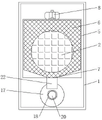
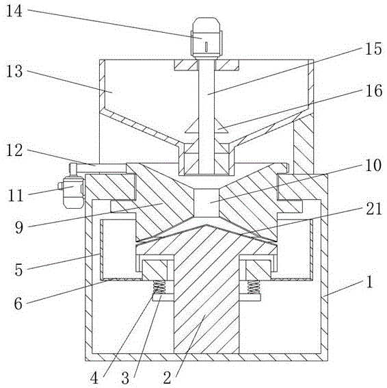
FIG. 1 is a schematic view of the cross-sectional structure of the present invention;
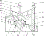
FIG. 2 is a schematic top view of the cross-sectional structure of the present invention;
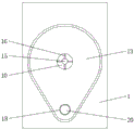
FIG. 3 is a schematic left side view of the cross-sectional structure of the present invention;
fig. 4 is a schematic view of the top-view cross-sectional structure of the hopper of the present invention.
In the figure: 1. the grinding device comprises a box body, 2, a lower grinding disc, 3, a supporting table, 4, a compression spring, 5, a screen disc, 6, a screen, 7, a discharge port, 8, a vibration motor, 9, an upper grinding disc, 10, a feed hole, 11, a first motor, 12, a belt, 13, a hopper, 14, a second motor, 15, a rotating shaft, 16, a stirring sheet, 17, a recovery hopper, 18, a material lifting pipe, 19, a third motor, 20, a spiral blade, 21, grinding grains, 22 and a flexible pipe.
Detailed Description
The technical solutions in the embodiments of the present invention will be described clearly and completely with reference to the accompanying drawings in the embodiments of the present invention, and it is obvious that the described embodiments are only some embodiments of the present invention, not all embodiments. Based on the embodiments in the present invention, all other embodiments obtained by a person skilled in the art without creative work belong to the protection scope of the present invention.
Referring to fig. 1-4, the present invention provides a technical solution: a semi-finished product ore grinding machine is disclosed, as shown in figure 1, figure 2 and figure 3, a lower grinding disc 2 is fixed at the rear side in a box body 1, a support table 3 is fixed at the outer side of the lower grinding disc 2, the upper surface of the lower grinding disc 2 is a cone, two taper holes with different tapers are arranged at the lower side of an upper grinding disc 9, the taper of the taper hole at the outer side of the upper grinding disc 9 is equal to the taper of the taper hole at the upper cone of the lower grinding disc 2, meanwhile, the taper of the taper hole at the outer side of the upper grinding disc 9 is smaller than the taper of the taper hole at the inner side of the upper grinding disc 9, so that ore moves outwards along the lower grinding disc 2, the lower grinding disc 2 is convenient to be matched with the upper grinding disc 9 to extrude the ore, a screen disc 5 is arranged at the upper side of the support table 3 through a compression spring 4, a screen 6 is fixed at the bottom of the screen disc 5, the rear end of the screen 6 is higher than the front end of the screen disc 5, a discharge port 7 arranged at the front side of the screen disc 5 is communicated with a recovery hopper 17 through a flexible pipe 22, unqualified ore enters the recovery hopper 17 through the discharge port 7 and the flexible pipe 22 without affecting the vibration of the screen disc 5, discharge gate 7 is opened to 5 front sides of screen tray, and 5 rear side fixed mounting of screen tray has vibrating motor 8, 1 rear side top of box rotates and is connected with the runner stone 9, and runner stone 9 middle part has seted up feed port 10, runner stone 9 lower surface and 2 upper surfaces of lower mill all are fixed with grinding line 21, grind the line 21 through the grinding line 21 on 2 of lower mill and the cooperation of grinding line 21 on the runner stone 9 and grind the ore, roughness has been increased, grinding effect has been improved, 11 fixed mounting of first motor is in 1 left side of box, and 11 of first motor is connected with runner stone 9 upside through belt 12, the runner stone 9 outside is provided with the hopper 13 of fixing at 1 top of box, and 13 central top fixed mounting of hopper has second motor 14.
As shown in fig. 1, 3 and 4, the second motor 14 is connected with a rotating shaft 15 which is rotatably connected with the hopper 13, and a stirring blade 16 is fixed on the outer side of the lower end of the rotating shaft 15, the central line of the rotating shaft 15 is positioned on the same vertical line with the central line of the feeding hopper 13, the central line of the upper grinding disc 9 and the central line of the lower grinding disc 2, the second motor 14 drives the stirring blade 16 to rotate through the rotating shaft 15, the stirring blade 16 loosens ores, so that the ores in the hopper 13 uniformly and continuously fall into the feeding hole 10, the recovery hopper 17 is fixed on the front side in the box 1, a material lifting pipe 18 which penetrates through the front side of the box 1 and is fixedly communicated with the front side of the hopper 13 is hung in the middle of the recovery hopper 17, a third motor 19 is fixedly installed on the front side of the hopper 13, and the third motor 19 is connected with a helical blade 20 which is rotatably connected with the front side of the material charging barrel and is arranged in the material lifting pipe 18, the central line of the helical blade 20 is positioned on the same vertical line with the central line of the recovery hopper 17, and the outer end of the helical blade 20 is attached to the inner wall of the material lifting pipe 18, and the third motor 19 drives the helical blade 20, so that the helical blade 20 can push unqualified ore at the bottom of the recovery hopper 17 to enter the hopper 13 through the material lifting pipe 18.
The working principle is as follows: when the semi-finished ore grinding machine is used, firstly, ores are put into a hopper 13, an external power supply is switched on, a second motor 14 is started, the second motor 14 drives a stirring sheet 16 to rotate through a rotating shaft 15, the stirring sheet 16 loosens the ores in the hopper 13, so that the ores fall between a lower grinding disc 2 and an upper grinding disc 9 through a feeding hole 10, a first motor 11 is started, the first motor 11 drives the upper grinding disc 9 to rotate through a belt 12, grinding grains 21 at the bottom of the upper grinding disc 9 and grinding grains 21 at the top of the lower grinding disc 2 are matched to grind the ores, at the moment, the upper grinding disc 9 and the lower grinding disc 2 are both axially stressed, compared with the traditional roller grinding, the deformation is small, the service life of the grinding machine is prolonged, the ground ores slide along a cone at the top of the lower grinding disc 2 and fall into a screen disc 5, a vibration motor 8 is started, the vibration motor 8 drives the screen disc 5 to vibrate, and a compression spring 4 on a support table 3 enables the screen disc 5 to vibrate more smoothly, the screen 6 screens out fine materials in vibration, because the screen 6 is high at the back and low at the front, unqualified ores on the surface of the screen 6 slide forwards along the screen 6 until the unqualified ores fall into the recovery hopper 17 through the discharge port 7 and the flexible pipe 22, the third motor 19 is started, the third motor 19 drives the helical blade 20 to rotate, the helical blade 20 pushes the unqualified ores in the recovery hopper 17 to enter the hopper 13 along the material lifting pipe 18, the unqualified ores are separated quickly and efficiently, the unqualified ores are thrown into the hopper 13 again for secondary grinding, the use is more convenient, and the whole work is finished.
The terms "central," "longitudinal," "lateral," "front," "rear," "left," "right," "vertical," "horizontal," "top," "bottom," "inner," "outer," and the like are used in the orientation or positional relationship indicated in the drawings for ease of description, but are not intended to indicate or imply that the device or element so referred to must have a particular orientation, be constructed and operated in a particular orientation, and are not to be considered limiting of the scope of the invention.
Although the present invention has been described in detail with reference to the foregoing embodiments, it will be apparent to those skilled in the art that modifications may be made to the embodiments or portions thereof without departing from the spirit and scope of the invention.