CN213947197U - Mould is used in plastic slab production - Google Patents
Mould is used in plastic slab production Download PDFInfo
- Publication number
- CN213947197U CN213947197U CN202022556700.2U CN202022556700U CN213947197U CN 213947197 U CN213947197 U CN 213947197U CN 202022556700 U CN202022556700 U CN 202022556700U CN 213947197 U CN213947197 U CN 213947197U
- Authority
- CN
- China
- Prior art keywords
- plate
- wall surface
- plastic
- mold
- die
- Prior art date
- Legal status (The legal status is an assumption and is not a legal conclusion. Google has not performed a legal analysis and makes no representation as to the accuracy of the status listed.)
- Expired - Fee Related
Links
Images



Landscapes
- Moulds For Moulding Plastics Or The Like (AREA)
Abstract
The invention relates to the technical field of plastic plate production and processing, and discloses a mold for plastic plate production, which comprises a bottom plate, wherein the bottom plate is in a rectangular plate shape, a square groove is formed in the upper wall surface of the bottom plate, and square grooves are respectively formed in the left side wall surface and the right side wall surface of the square groove on the bottom plate, when a die-casting plate moves downwards to extrude a plastic dissolving plate arranged in the mold, the mold can move downwards to the lower part of the square groove on the bottom plate under the extrusion of the die-casting plate and is jointed with an extrusion block, when the die-casting is completed, a driving plate leaves the die-casting plate, the extrusion block jacks up a hole plug through the elasticity of a pressure spring, so that the plastic dissolving plate arranged in the mold is also jacked up by the hole plug, when the die-casting plate also moves upwards, the plastic dissolving plate can be sucked by the negative pressure in an annular block and directly taken out of the mold, so that the plastic dissolving plate can be taken out of the mold under the dual functions of the pressure spring and the annular block, thereby achieving the effects of fast demoulding and improving the processing efficiency of the plastic dissolving plate.
Description
Technical Field
The invention relates to the technical field of plastic plate production and processing, in particular to a mold for plastic plate production.
Background
The plastic plate is made of plastic, the plastic is a synthetic high molecular compound, the shape and style can be freely changed, the plastic is a material which is polymerized by monomer raw materials through synthesis or condensation reaction, and consists of synthetic resin, fillers, plasticizers, stabilizers, lubricants, pigments and other additives, the main component of the plastic is synthetic resin, the plastic can be divided into two types of thermosetting and thermoplastic, the former can not be molded again for use, and the latter can be produced repeatedly.
At present when producing the plastic slab, generally put into the mould with plastics earlier, then process it through the hot press for the hardness of plastic slab is higher and the outward appearance can be more pleasing to the eye, but after the hot pressing is accomplished, the plastic slab can be because the temperature on its surface is too high, simultaneously again because the plastic slab is at the mould internal cooling rate slow, lead to the plastic slab to adhere each other with the internal surface of mould together easily, thereby lead to the plastic slab drawing of patterns difficulty, influence machining efficiency, for this reason, we provide a mould for plastic slab production.
Disclosure of Invention
Technical problem to be solved
The invention mainly solves the technical problems in the prior art and provides a mold for producing a plastic plate.
(II) technical scheme
In order to achieve the purpose, the invention adopts the following technical scheme that the mold for producing the plastic plate comprises a bottom plate, wherein the bottom plate is in a rectangular plate shape, a square groove is formed in the upper wall surface of the bottom plate, square grooves are respectively formed in the left side wall surface and the right side wall surface of the square groove on the bottom plate, the square groove is in a rectangular groove shape, a movable placing mold is arranged in the square groove on the bottom plate, the placing mold is hollow, slide blocks which correspond to the two square grooves are respectively fixedly arranged on the left side wall surface and the right side wall surface of the placing mold, the two slide blocks and the two square grooves are mutually connected in a friction mode, a plastic dissolving plate is arranged in the placing mold, two circular holes which are in mirror symmetry are formed in the inner bottom wall surface of the placing mold, hole plugs which correspond to the circular holes are respectively arranged in the circular holes, and the two circular holes and the two hole plugs are respectively sealed and attached together, the lower wall surface of the inner part of the square groove on the bottom plate is provided with two cylinders which are in mirror symmetry, the cylinders are hollow, the upper ends of the two cylinders are respectively penetrated with a resisting block which is in a circular block shape, the insides of the two cylinders are respectively provided with a limiting block which is in a circular block shape, the upper ends of the two limiting blocks are respectively fixedly connected with the lower ends of the two resisting blocks, the outer wall surfaces of the two limiting blocks are respectively movably jointed with the inner wall surfaces of the two cylinders, the insides of the two cylinders are respectively provided with a pressure spring, the upper ends of the two pressure springs are respectively fixedly connected with the lower ends of the two limiting blocks, the lower ends of the two pressure springs are respectively fixedly connected with the inner bottom ends of the two cylinders, the upper ends of the two resisting blocks are respectively fixedly provided with an extruding block which is mutually corresponding to the hole plugs, the extruding blocks are in a circular block shape, and the upper ends of the two extruding blocks are respectively jointed with the lower ends of the two hole plugs, the inside left and right sides wall face of placing the mould has seted up the second square groove respectively, every two wall faces are seted up two mirror symmetry's interior spout respectively around the inside of second square groove, and interior spout is the rectangle groove form.
Preferably, two the inside of second square groove is provided with the circle axle that can remove about respectively, every both ends respectively with two around the circle axle the movable joint of interior spout is in the same place, two the outer wall of circle axle has driving wheel, driving wheel for circular gyro wheel through loose bearing swing joint respectively, two the outer wall of driving wheel is provided with the friction line that the equidistance was arranged, per two the inside of interior spout is provided with the spring respectively.
Preferably, the left end and the right end of each two springs are respectively fixedly connected with the outer wall surfaces of each two circular shafts and the right wall surface of the inner portion of each two inner chutes, the upper end of the plastic dissolving plate is provided with a die-casting plate, the upper end of the die-casting plate is provided with a driving plate, the die-casting plate is movably connected with the driving plate through two telescopic blocks, and the upper end of the driving plate is provided with a driving column.
Preferably, the driving column is in driving connection with external driving equipment, an annular block is arranged inside the die-casting plate, the annular block is hollow, a circular hole is formed in the lower wall surface of the annular block, an inner pipe penetrates through the upper wall surface of the die-casting plate, the inner pipe is in a circular tubular shape, the inner part of the inner pipe is hollow, and the inner pipe is communicated with the inner part of the annular block.
Preferably, an extrusion rod capable of moving up and down is arranged in the inner tube, the extrusion rod is in a circular rod shape, the upper end of the extrusion rod is fixedly connected with the drive plate, a piston is fixedly mounted at the lower end of the extrusion rod, the outer wall surface of the piston is movably attached to the inner wall surface of the inner tube, and the lower wall surface of the die-casting plate is attached to and extruded from the upper wall surface of the plastic dissolving plate.
Advantageous effects
The invention provides a mold for producing a plastic plate. The method has the following beneficial effects:
(1) when the die casting plate moves downwards to extrude the plastic dissolving plate arranged in the die, the placing die can move towards the lower part of the inner part of the square groove on the bottom plate under the extrusion of the die-casting plate and is jointed with the extrusion block, after the die-casting plate is contacted with the plastic dissolving plate, the hole below the annular block is also contacted with the upper wall surface of the plastic dissolving plate, and the air in the inner pipe is extruded and discharged by the extrusion rod, when the die casting is finished and the driving plate leaves the die casting plate, the extrusion block jacks up the hole plug through the elasticity of the compression spring, so that the plastic dissolving plate placed in the die is also jacked up by the hole plug, when the die-casting plate also moves upwards, the plastic melting plate is sucked by the negative pressure in the annular block and is directly taken out of the die, therefore, the plastic dissolving plate can finish material taking under the dual actions of the pressure spring and the annular block, so that the effects of quickly demoulding and improving the processing efficiency of the plastic dissolving plate are achieved.
(2) This mould is used in plastic slab production, when plastics dissolve the board and place the mould inside to placing the mould top when removing, at this moment place inside two driving wheels of mould can pop out the second square groove through the spring inside, at this moment dissolve the board with two driving wheel contact backs when plastics, two driving wheels can carry out arbitrary rotations, at this moment plastics dissolve the board will improve self translation rate under two driving wheel rotation drives to reach the effect of quick ejection of compact.
(3) This mould is used in plastic slab production, the outer wall of two driving wheels is provided with friction line, and friction line takes the driving wheel outer wall comparatively outstanding, dissolves the board when the ejection of compact by the hole stopper jack-up when plastics, and at this moment plastics dissolve the board can contact with two driving wheels, and friction line on the driving wheel outer wall also can dissolve board left and right both sides wall contact with plastics like this, and at this moment friction line will increase two driving wheels and plastics and dissolve the frictional force between the board to reach the effect that improves the ejection of compact rate.
Drawings
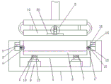
FIG. 1 is an overall structural view of the present invention;
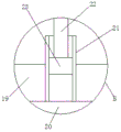
FIG. 2 is an enlarged view of A of FIG. 1 according to the present invention;
FIG. 3 is a partial schematic view of a cylinder according to the present invention;
FIG. 4 is an enlarged view of B of FIG. 1 in accordance with the present invention;
FIG. 5 is a partial schematic view of a rub mark of the present invention.
Illustration of the drawings:
1. a base plate; 2. rubbing the lines; 3. a square groove; 4. placing a mould; 5. a slider; 6. plastic dissolving plates; 7. a circular hole; 8. a hole plug; 9. a cylinder; 10. a resisting block; 11. a limiting block; 12. a pressure spring; 13. extruding the block; 14. a second square groove; 15. an inner chute; 16. a circular shaft; 17. driving the wheel; 18. a spring; 19. die-casting the plate; 20. a ring block; 21. an inner tube; 22. an extrusion stem; 23. a piston.
Detailed Description
The technical scheme of the invention is further specifically described by the following embodiments and the accompanying drawings.
Example (b): a mold for producing plastic plates is shown in figures 1-5, and comprises a bottom plate 1, wherein the bottom plate 1 is rectangular plate-shaped, a square groove is formed in the upper wall surface of the bottom plate 1, square grooves 3 are respectively formed in the left side wall surface and the right side wall surface of the square groove on the bottom plate 1, the square grooves 3 are rectangular groove-shaped, a movable placing mold 4 is arranged in the square groove on the bottom plate 1, the placing mold 4 is hollow, the placing mold 4 is of a conventional structure and is not described herein, sliding blocks 5 corresponding to the two square grooves 3 are respectively fixedly arranged on the left side wall surface and the right side wall surface of the placing mold 4, the two sliding blocks 5 and the two square grooves 3 are in friction connection with each other, a plastic dissolving plate 6 is arranged in the placing mold 4, the plastic dissolving plate 6 is of a conventional structure and is not described herein, two circular holes 7 in mirror symmetry are formed in the inner bottom side wall surface of the placing mold 4, hole plugs 8 corresponding to the circular holes 7 are respectively arranged in the two circular holes 7, the two round holes 7 and the two hole plugs 8 are respectively sealed and attached together, the lower wall surface of the inner part of the square groove on the bottom plate 1 is provided with two cylinders 9 which are in mirror symmetry, the interiors of the cylinders 9 are hollow, the upper ends of the two cylinders 9 are respectively penetrated with a resisting block 10, the resisting block 10 is in a round block shape, the interiors of the two cylinders 9 are respectively provided with a limiting block 11, the limiting blocks 11 are in a round block shape, the upper ends of the two limiting blocks 11 are respectively fixedly connected with the lower ends of the two resisting blocks 10, the outer wall surfaces of the two limiting blocks 11 are respectively movably attached with the inner wall surfaces of the two cylinders 9, the interiors of the two cylinders 9 are respectively provided with a pressure spring 12, the upper ends of the two pressure springs 12 are respectively fixedly connected with the lower ends of the two limiting blocks 11, the lower ends of the two pressure springs 12 are respectively fixedly connected with the inner bottom ends of the two cylinders 9, and the upper ends of the two resisting blocks 10 are respectively fixedly provided with an extrusion block 13 which corresponds to the hole plugs 8, the extrusion blocks 13 are in a circular block shape, the upper ends of the two extrusion blocks 13 are respectively attached to the lower ends of the two hole plugs 8, the left and right side wall surfaces in the mold 4 are respectively provided with a second square groove 14, the front and rear side wall surfaces in each second square groove 14 are respectively provided with two mirror-symmetrical inner sliding grooves 15, the inner sliding grooves 15 are in a rectangular groove shape, the two second square grooves 14 are respectively internally provided with a round shaft 16 capable of moving left and right, the front and rear ends of each round shaft 16 are respectively movably clamped with the two inner sliding grooves 15, the outer wall surfaces of the two round shafts 16 are respectively movably connected with driving wheels 17 through movable bearings, the driving wheels 17 are circular rolling wheels, the outer wall surfaces of the two driving wheels 17 are provided with friction grains 2 which are arranged at equal intervals, the springs 18 are respectively arranged in the two inner sliding grooves 15, the left and right ends of each two springs 18 are respectively fixedly connected with the outer wall surfaces of each two round shafts 16 and the right wall surfaces of each inner sliding grooves 15, the upper end of the plastic dissolving plate 6 is provided with a die-casting plate 19, the die-casting plate 19 is of an existing structure and is not described herein, the upper end of the die-casting plate 19 is provided with a drive plate, the die-casting plate 19 is movably connected with the drive plate through two telescopic blocks, the upper end of the drive plate is provided with a drive column, the drive column is connected with an external drive device in a driving manner, the die-casting plate 19 is internally provided with an annular block 20, the annular block 20 is internally hollow, the lower wall surface of the annular block 20 is provided with a circular hole, the upper wall surface of the die-casting plate 19 is penetrated with an inner tube 21, the inner tube 21 is in a circular tubular shape, the inner tube 21 is hollow, the inner tube 21 is communicated with the annular block 20, the inner tube 21 is internally provided with a squeezing rod 22 capable of moving up and down, the squeezing rod 22 is in a circular rod shape, the upper end of the squeezing rod 22 is fixedly connected with the drive plate, the lower end of the squeezing rod 22 is fixedly provided with a piston 23, the outer wall surface of the piston 23 is movably attached to the inner wall surface of the inner tube 21, the lower wall surface of the die-cast plate 19 is pressed against the upper wall surface of the plastic melt plate 6.
The working principle of the invention is as follows: when the plastic dissolving plate 6 is used, the plastic dissolving plate 6 is firstly placed at the inner bottom end of the placing mold 4, the driving plate at the upper end of the die casting plate 19 is driven by an external driving device to enable the die casting plate 19 to extrude and shape the plastic dissolving plate 6 towards the inner part of the placing mold 4, the annular block 20 is attached to the upper wall surface of the plastic dissolving plate 6, the driving plate drives the piston 23 to discharge the gas in the inner pipe 21 from the inner pipe 21 through the hole below the annular block 20 when extruding downwards, the placing mold 4 is driven by the die casting plate 19 to move in the square groove on the bottom plate 1 when extruding the die casting plate 19 downwards to extrude the hole plug 8 on the placing mold 4 to the extruding block 13 in the groove above the bottom plate 1, and when the driving plate above the die casting plate 19 firstly leaves the die casting plate 19 after the die casting and shape of the plastic dissolving plate 6, the extruding block 13 is upwards pushed and extruded under the resilience of the compression spring 12, at this moment, the plastic dissolving plate 6 placed in the mold 4 can be popped out of the lower wall surface of the mold 4 under the impact of the hole plug 8, when the plastic dissolving plate 6 passes through the driving wheel 17, the plastic dissolving plate 6 can be popped out of the mold 4 under the driving of the driving wheel 17, and at this moment, when the driving plate moves upwards, the die-casting plate 19 can directly drive the plastic dissolving plate 6 out of the mold 4 through the negative pressure in the annular block 20 to complete material taking.
The foregoing shows and describes the general principles and features of the present invention, together with the advantages thereof. It will be understood by those skilled in the art that the present invention is not limited to the embodiments described above, which are described in the specification and illustrated only to illustrate the principle of the present invention, but that various changes and modifications may be made therein without departing from the spirit and scope of the present invention, which fall within the scope of the invention as claimed. The scope of the invention is defined by the appended claims and equivalents thereof.
Claims (6)
1. The utility model provides a mould is used in plastic slab production, includes bottom plate (1), its characterized in that: the upper wall surface of the bottom plate (1) is provided with square grooves, the left side wall surface and the right side wall surface of the inside of the square groove on the bottom plate (1) are respectively provided with the square grooves (3), the inside of the square groove on the bottom plate (1) is provided with a movable placing mold (4), the left side wall surface and the right side wall surface of the placing mold (4) are respectively and fixedly provided with a slide block (5) which corresponds to the two square grooves (3), the inside of the placing mold (4) is provided with a plastic dissolving plate (6), the inside bottom wall surface of the inside of the placing mold (4) is provided with two circular holes (7) which are in mirror symmetry, the lower wall surface of the inside of the square groove on the bottom plate (1) is provided with two cylinders (9) which are in mirror symmetry, the upper ends of the two cylinders (9) are respectively penetrated with a supporting block (10), the insides of the two cylinders (9) are respectively provided, the left side wall surface and the right side wall surface in the placing mold (4) are respectively provided with a second square groove (14), the front side wall surface and the rear side wall surface in the second square groove (14) are respectively provided with two mirror symmetry inner sliding grooves (15), the two second square grooves (14) are respectively internally provided with a round shaft (16) capable of moving left and right, the outer wall surfaces of the two round shafts (16) are respectively movably connected with driving wheels (17) through movable bearings, the outer wall surfaces of the two driving wheels (17) are provided with friction grains (2) which are arranged at equal intervals, the inner sliding grooves (15) are respectively internally provided with a spring (18), the upper end of the plastic dissolving plate (6) is provided with a die-casting plate (19), the upper end of the die-casting plate (19) is provided with a driving plate, the die-casting plate (19) is movably connected with the driving plate through two telescopic blocks, and the upper end of the driving plate is provided with a driving column, the driving column is in driving connection with external driving equipment, an annular block (20) is arranged inside a die-casting plate (19), a round hole is formed in the lower wall face of the annular block (20), an inner tube (21) penetrates through the upper wall face of the die-casting plate (19), an extrusion rod (22) capable of moving up and down is arranged inside the inner tube (21), and a piston (23) is fixedly mounted at the lower end of the extrusion rod (22).
2. The mold for producing a plastic plate according to claim 1, wherein: two slider (5) and two mutual frictional connection of square groove (3) is in the same place, two the inside of round hole (7) be provided with respectively with the hole stopper (8) that round hole (7) correspond each other, two round holes (7) are in the same place with two hole stoppers (8) sealed laminating respectively.
3. The mold for producing a plastic plate according to claim 1, wherein: the upper ends of the two limiting blocks (11) are fixedly connected with the lower ends of the two abutting blocks (10) respectively, the outer wall surfaces of the two limiting blocks (11) are movably attached to the inner wall surfaces of the two cylinders (9) respectively, the upper ends of the two pressure springs (12) are fixedly connected with the lower ends of the two limiting blocks (11) respectively, and the lower ends of the two pressure springs (12) are fixedly connected with the inner bottom ends of the two cylinders (9) respectively.
4. The mold for producing a plastic plate according to claim 2, wherein: the upper ends of the two abutting blocks (10) are respectively and fixedly provided with an extrusion block (13) which corresponds to the hole plug (8), and the upper ends of the two extrusion blocks (13) are respectively attached to the lower ends of the two hole plugs (8).
5. The mold for producing a plastic plate according to claim 1, wherein: the front end and the rear end of each circular shaft (16) are movably clamped with the two inner chutes (15) together, and the left end and the right end of each spring (18) are fixedly connected with the outer wall surfaces of the circular shafts (16) and the right wall surfaces of the inner chutes (15).
6. The mold for producing a plastic plate according to claim 1, wherein: the upper end of the extrusion rod (22) is fixedly connected with the drive plate, the outer wall surface of the piston (23) is movably attached to the inner wall surface of the inner tube (21), and the lower wall surface of the die-casting plate (19) is attached to and extruded with the upper wall surface of the plastic dissolving plate (6).
Priority Applications (1)
| Application Number | Priority Date | Filing Date | Title |
|---|---|---|---|
| CN202022556700.2U CN213947197U (en) | 2020-11-09 | 2020-11-09 | Mould is used in plastic slab production |
Applications Claiming Priority (1)
| Application Number | Priority Date | Filing Date | Title |
|---|---|---|---|
| CN202022556700.2U CN213947197U (en) | 2020-11-09 | 2020-11-09 | Mould is used in plastic slab production |
Publications (1)
| Publication Number | Publication Date |
|---|---|
| CN213947197U true CN213947197U (en) | 2021-08-13 |
Family
ID=77207617
Family Applications (1)
| Application Number | Title | Priority Date | Filing Date |
|---|---|---|---|
| CN202022556700.2U Expired - Fee Related CN213947197U (en) | 2020-11-09 | 2020-11-09 | Mould is used in plastic slab production |
Country Status (1)
| Country | Link |
|---|---|
| CN (1) | CN213947197U (en) |
Cited By (1)
| Publication number | Priority date | Publication date | Assignee | Title |
|---|---|---|---|---|
| CN117621397A (en) * | 2024-01-26 | 2024-03-01 | 甘肃三合塑胶科技有限公司 | Plastic plate forming device and forming method |
-
2020
- 2020-11-09 CN CN202022556700.2U patent/CN213947197U/en not_active Expired - Fee Related
Cited By (1)
| Publication number | Priority date | Publication date | Assignee | Title |
|---|---|---|---|---|
| CN117621397A (en) * | 2024-01-26 | 2024-03-01 | 甘肃三合塑胶科技有限公司 | Plastic plate forming device and forming method |
Similar Documents
| Publication | Publication Date | Title |
|---|---|---|
| CN210547477U (en) | Stamping die convenient to drawing of patterns | |
| CN207386480U (en) | A kind of hardware die for processing | |
| CN110815749A (en) | Mould fixing device for small-size product | |
| CN118720109B (en) | Quick shedder of metal casting | |
| CN210969634U (en) | Mould for plastic processing convenient to get material | |
| CN220146560U (en) | Automobile decoration strip production die | |
| CN221089781U (en) | Injection mold for automotive interior cover plate | |
| CN113459434A (en) | Injection mold | |
| CN118700466A (en) | Tire mold ejection device | |
| CN205871068U (en) | Automotive interior spare injection mold | |
| CN215903880U (en) | Injection mold for preparing engineering plastic parts | |
| CN108097918A (en) | Two-way ejecting mechanism, Double Tops board mold and the extrusion method of extruder | |
| CN211221780U (en) | Three-color injection mold convenient to demolding | |
| CN111016083B (en) | Injection molding and stamping die for producing parts with holes | |
| CN209869246U (en) | Three-dimensional embedded type die | |
| CN222242356U (en) | Ejection mechanism for machining oil pan die | |
| CN220883120U (en) | HDPE bucket injection moulding device | |
| CN219054074U (en) | Inner and outer mould taper fit die set for grinding wheel production | |
| CN219813076U (en) | Tea cake pressing machine | |
| CN220297680U (en) | Plastic product processing die | |
| CN219357628U (en) | Production mould for manufacturing wheels | |
| CN220661548U (en) | Multi-station synchronous forming die | |
| CN221622538U (en) | Quick demoulding concrete filling mould | |
| CN212636477U (en) | A constant temperature and efficient injection mold equipment | |
| CN216884929U (en) | Porous quick forming die that fills |
Legal Events
| Date | Code | Title | Description |
|---|---|---|---|
| GR01 | Patent grant | ||
| GR01 | Patent grant | ||
| CF01 | Termination of patent right due to non-payment of annual fee | ||
| CF01 | Termination of patent right due to non-payment of annual fee |
Granted publication date: 20210813 |