CN213944999U - Numerical control drilling machine is with anchor clamps of being convenient for adjust - Google Patents
Numerical control drilling machine is with anchor clamps of being convenient for adjust Download PDFInfo
- Publication number
- CN213944999U CN213944999U CN202022039563.5U CN202022039563U CN213944999U CN 213944999 U CN213944999 U CN 213944999U CN 202022039563 U CN202022039563 U CN 202022039563U CN 213944999 U CN213944999 U CN 213944999U
- Authority
- CN
- China
- Prior art keywords
- adjusting
- drilling machine
- box
- numerical control
- gear
- Prior art date
- Legal status (The legal status is an assumption and is not a legal conclusion. Google has not performed a legal analysis and makes no representation as to the accuracy of the status listed.)
- Expired - Fee Related
Links
Images



Landscapes
- Drilling And Boring (AREA)
Abstract
The utility model discloses a numerical control drilling machine is with anchor clamps of being convenient for adjust, concretely relates to drilling machine anchor clamps field, including the under casing, the inboard sliding connection of under casing has slewing mechanism, and the top fixed mounting of under casing has the loop bar, and the top fixed mounting of under casing has actuating mechanism, and angle adjust knob and height adjust knob are installed in proper order to one side of spacing subassembly, and the top fixed mounting of under casing has the transmission case, and the fixed tilting adjustment mechanism that has cup jointed in inside of adjusting support box. The utility model fixes the workpieces with different inclinations through the structural design of the limiting mechanism, the structure of the adjusting support box and the structural design of the inclination adjusting mechanism, thereby improving the practicability and the clamping effect of the clamp, improving the processing yield of the numerical control drilling machine and reducing the waste of the processing cost; through the structural design of the bottom box structure, the transmission box structure, the driving mechanism structure and the angle adjusting wheel, the effect that the angle of the clamp can be adjusted when the clamp fixes a workpiece is achieved, the adjusting process is simplified, and the machining precision is improved.
Description
Technical Field
The utility model relates to a drilling machine anchor clamps technical field, more specifically says, the utility model specifically is a numerical control drilling machine is with anchor clamps of being convenient for adjust.
Background
In the machining field, the numerical control drilling machine has comparatively extensive application, and the drilling machine mainly uses the drill bit to process the hole on the work piece, uses the drill bit rotation to primary motion usually, and the feed motion is done in the drill bit axial displacement to realize the processing purpose, need fix the work piece with anchor clamps at the in-process that the drilling machine processed to ensure that the work piece does not take place the skew at the in-process of processing.
The existing numerical control drilling machine clamp is mainly used for screwing a screw rod manually, workpieces are fixed from two sides, the clamp is fixed in structure, inclined workpieces are difficult to clamp stably, the clamp is easy to loosen during actual machining, the numerical control drilling machine cannot accurately machine, machining failure is caused, machining cost is wasted, in the process of multi-angle drilling machining of the numerical control drilling machine, complicated position adjustment needs to be carried out on the workpieces, and machining precision is easily reduced due to misoperation in the adjusting process.
Therefore, it is desirable to provide a clamp for a numerically controlled drilling machine that is easy to adjust.
SUMMERY OF THE UTILITY MODEL
In order to overcome the above-mentioned defect of prior art, the embodiment of the utility model provides a numerical control drilling machine is with anchor clamps of being convenient for adjust through stop gear structure, regulation support box structure, slope adjustment mechanism structure, under casing structure, transmission case structure, actuating mechanism structure and angle modulation wheel structural design to solve the problem that proposes in the above-mentioned background art.
In order to achieve the above object, the utility model provides a following technical scheme: a numerical control drilling machine is with anchor clamps convenient to adjust, includes the under casing, the inboard sliding connection of under casing has slewing mechanism, slewing mechanism includes under casing dish, support column and top gear, the top fixed mounting of under casing dish has the loop bar, the tooth's socket has been seted up on the top of under casing dish, the top fixed mounting of under casing has actuating mechanism, actuating mechanism includes the motor, the fixed cover of output shaft of motor is equipped with the driving gear, the outer edge of driving gear and the inboard intermeshing of tooth's socket, the inboard threaded connection of loop bar has the lead screw, the top threaded connection of lead screw has stop gear, stop gear includes spacing subassembly, angle adjust knob and height adjust knob are installed in proper order to one side of spacing subassembly, the one end fixed connection of angle adjust knob and spacing subassembly, the one end fixedly connected with elevating gear of height adjust knob, the outer edge of lifting gear and the outside intermeshing of lead screw, the top fixed mounting of under casing has the transmission case, driven gear has been cup jointed in the inboard activity of transmission case, driven gear's outer edge and top gear intermeshing, the top fixedly connected with regulation support box of transmission case, the fixed tilt adjustment mechanism that has cup jointed in inside of regulation support box, tilt adjustment mechanism includes knob, adjustment mechanism and backup pad, the inboard fixed mounting of knob has the slope lead screw, the inboard fixed mounting of regulation support box has coupling assembling, the outside threaded connection of slope lead screw has the screw external member, coupling assembling's side fixedly connected with slide bar, the outside sliding connection of slide bar has the slip external member, the inboard sliding connection of screw external member and slip external member has the connecting rod, the top of screw external member and slip external member and the bottom fixed connection of backup pad, an angle adjusting wheel is movably sleeved at the bottom end inside the adjusting and supporting box.
In a preferred embodiment, a rotary joint is fixedly mounted at the top end of the adjusting support box, a top plate is slidably connected to the outer side of the rotary joint, and an elastic mechanism is fixedly connected to one end of the top plate.
In a preferred embodiment, the inner side of the angle adjusting wheel is provided with a plurality of rotating grooves, the rotating grooves are uniformly distributed on the inner side of the angle adjusting wheel, and the outer side of the driven gear is in sliding connection with the inner side of the rotating grooves.
In a preferred embodiment, the knob and the adjusting mechanism are obliquely arranged inside the adjusting support box, and the inclination angle is less than thirty degrees.
In a preferred embodiment, the bottom end of the inside of the bottom case is movably sleeved with a ball, and the outer side of the ball is slidably connected with the bottom end of the rotating mechanism.
In a preferred embodiment, the number of the loop bars and the limiting mechanisms is several, and the loop bars and the limiting mechanisms are uniformly distributed at the top end of the bottom turntable.
The utility model discloses a technological effect and advantage:
1. the utility model discloses a stop gear structure, regulation support box structure and slope adjustment mechanism structural design utilize the slope adjustment mechanism to adjust the roof gradient of regulation support box, utilize the stop gear of adjustable height and spacing angle, fix the work piece of different gradients, improved the practicality and the centre gripping effect of anchor clamps, promoted the processing yield of numerically-controlled drilling machine, reduced the waste of processing cost;
2. the utility model discloses a bottom case structure, transmission case structure, actuating mechanism structure and angular adjustment wheel structural design utilize actuating mechanism to make slewing mechanism rotate, make driven gear drive angular adjustment wheel rotate, have reached the effect that anchor clamps can carry out angle modulation when fixed work piece, have simplified the accommodation process, have improved the machining precision.
Drawings
Fig. 1 is a schematic view of the overall structure of the present invention.
Fig. 2 is a schematic view of the whole internal structure of the present invention.
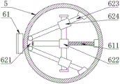
Fig. 3 is a top view of the adjusting mechanism of the present invention.
Fig. 4 is a top view of the angle adjusting wheel structure of the present invention.
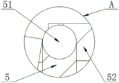
Fig. 5 is a schematic structural diagram of a position a in fig. 2 according to the present invention.
The reference signs are: 1. a bottom box; 2. a loop bar; 3. a limiting mechanism; 4. a transmission case; 5. adjusting the support box; 6. a tilt adjustment mechanism; 7. a drive mechanism; 11. a rotating mechanism; 31. a limiting component; 32. an angle adjusting knob; 33. a height adjustment knob; 41. a driven gear; 51. a rotating joint; 52. a top plate; 61. a knob; 62. an adjustment mechanism; 63. a support plate; 64. an angle adjustment wheel; 71. a motor; 72. a driving gear; 611. inclining the screw rod; 621. a connecting assembly; 622. a threaded sleeve; 623. a slide bar; 624. a sliding sleeve member; 641. the groove is rotated.
Detailed Description
The technical solutions in the embodiments of the present invention will be described clearly and completely with reference to the accompanying drawings in the embodiments of the present invention, and it is obvious that the described embodiments are only some embodiments of the present invention, not all embodiments. Based on the embodiments in the present invention, all other embodiments obtained by a person skilled in the art without creative work belong to the protection scope of the present invention.
The adjustable clamp for the numerical control drilling machine shown in the attached figures 1-5 comprises a bottom box 1, wherein the inner side of the bottom box 1 is connected with a rotating mechanism 11 in a sliding manner, the rotating mechanism 11 comprises a bottom rotating disk, a supporting column and a top gear, a loop bar 2 is fixedly arranged at the top end of the bottom rotating disk, a tooth socket is arranged at the top end of the bottom rotating disk, a driving mechanism 7 is fixedly arranged at the top end of the bottom box 1, the driving mechanism 7 comprises a motor 71, a driving gear 72 is fixedly sleeved on an output shaft of the motor 71, the outer edge of the driving gear 72 is meshed with the inner side of the tooth socket, a lead screw is connected with the inner side of the loop bar 2 through a thread, a limiting mechanism 3 is connected with the top end of the lead screw through a thread, the limiting mechanism 3 comprises a limiting component 31, an angle adjusting knob 32 and a height adjusting knob 33 are sequentially arranged on one side of the limiting component 31, one end of the angle adjusting knob 32 is fixedly connected with one end of the limiting component 31, one end of the height adjusting knob 33 is fixedly connected with a lifting gear, the outer edge of the lifting gear is meshed with the outer side of the screw rod, the top end of the bottom box 1 is fixedly provided with a transmission box 4, the inner side of the transmission box 4 is movably sleeved with a driven gear 41, the outer edge of the driven gear 41 is meshed with the top gear, the top end of the transmission box 4 is fixedly connected with an adjusting support box 5, the inner part of the adjusting support box 5 is fixedly sleeved with an inclination adjusting mechanism 6, the inclination adjusting mechanism 6 comprises a knob 61, an adjusting mechanism 62 and a support plate 63, the inner side of the knob 61 is fixedly provided with an inclined screw rod 611, the inner side of the adjusting support box 5 is fixedly provided with a connecting assembly 621, the outer side of the inclined screw rod 611 is in threaded connection with a thread assembly 622, the side surface of the connecting assembly 621 is fixedly connected with a slide rod 623, the outer side of the slide rod 623 is slidably connected with a sliding assembly 624, and the inner sides of the thread assembly 622 and the sliding assembly 624 are slidably connected with a connecting rod, the top ends of the thread sleeve 622 and the sliding sleeve 624 are fixedly connected with the bottom end of the supporting plate 63, and the bottom end inside the adjusting supporting box 5 is movably sleeved with the angle adjusting wheel 64.
The implementation mode is specifically as follows: through the structural design of the limiting mechanism 3, the structure of the adjusting support box 5 and the structural design of the inclination adjusting mechanism 6, the inclination adjusting mechanism 6 is used for adjusting the inclination of the top plate 52 of the adjusting support box 5, and the limiting mechanism 3 with adjustable height and limiting angle is used for fixing workpieces with different inclinations, so that the practicability and the clamping effect of the clamp are improved, the machining yield of the numerical control drilling machine is improved, and the waste of the machining cost is reduced; through the structural design of the bottom box 1, the transmission box 4, the driving mechanism 7 and the angle adjusting wheel 64, the driving mechanism 7 is utilized to rotate the rotating mechanism 11, so that the driven gear 41 drives the angle adjusting wheel 64 to rotate, the effect that the angle of the clamp can be adjusted when a workpiece is fixed is achieved, the adjusting process is simplified, and the processing precision is improved.
Wherein, the top end fixed mounting who adjusts support box 5 has rotary joint 51, and rotary joint 51's outside sliding connection has roof 52, and the one end fixed connection of roof 52 has elastic mechanism, utilizes rotary joint 51 and elastic mechanism's setting, has reached roof 52 and can follow the rotation of knob 61 and the effect of slope
Wherein, the rotation groove 641 has been seted up to the inboard of angle adjustment wheel 64, the quantity of rotation groove 641 is a plurality of, a plurality of rotates groove 641 evenly distributed in angle adjustment wheel 64's inboard, driven gear 41's the outside and the inboard sliding connection who rotates groove 641, utilize the sliding connection between driven gear 41 outside denticle and the rotation groove 641 inboard, make angle adjustment wheel 64 carry out intermittent type formula along with driven gear 41's rotation and rotate, actuating mechanism 7's rotation makes the 5 intermittent type small-angle rotations of regulation support box, thereby reach the effect of adjusting the work piece angle.
Wherein, knob 61 and adjustment mechanism 62 slope sets up in the inside of adjusting support box 5, and the inclination is less than thirty degrees, makes the top surface that adjusts support box 5 can start the slope slowly along with the rotation of knob 61, avoids the too big work piece slip that causes of angle on inclined plane simultaneously.
Wherein, the inside bottom activity of under casing 1 has cup jointed the ball, and the outside and the bottom sliding connection of slewing mechanism 11 of ball make slewing mechanism 11's rotation process more steady smooth and easy.
Wherein, loop bar 2 and stop gear 3's quantity is a plurality of, and a plurality of loop bar 2 and stop gear 3 evenly distributed have increased workpiece surface's clamping effect point on the top of end carousel, have improved the centre gripping effect of anchor clamps.
The utility model discloses the theory of operation:
the first step is as follows: connecting a motor 71 with an operation panel of the numerically-controlled drilling machine, placing an inclined workpiece on the top surface of the adjusting support box 5, rotating the knob 61 to rotate the inclined screw rod 611, moving the thread sleeve 622 rightwards to drive the sliding sleeve 624 to simultaneously slide on the outer side of the sliding rod 623, so that the height of the support plate 63 is lowered, the rotating joint 51 begins to incline, and adjusting the rotating joint 51 until the axis of the workpiece is at a vertical inclined angle;
the second step is that: the height adjusting knob 33 is rotated to enable the limiting assembly 31 to ascend above the workpiece, the angle adjusting knob 32 is rotated to adjust the limiting angle of the limiting assembly 31, and the angle adjusting knob 32 and the height adjusting knob 33 are rotated to enable the limiting assembly 31 to act on the effective clamping point of the workpiece with the maximum clamping force and the optimal clamping angle, so that the clamping effect of the clamp is improved;
the third step: the operation panel of the numerically-controlled drilling machine is operated, the output power of the motor 71 is adjusted to adjust the rotating speed of the rotating mechanism 11, the effect of adjusting the rotating speed of the supporting box 5 is achieved through the transmission of the driven gear 41, and when a workpiece rotates to a required machining position, the operation panel of the numerically-controlled drilling machine is operated to enable the motor 71 to be turned off.
The points to be finally explained are: first, in the description of the present application, it should be noted that, unless otherwise specified and limited, the terms "mounted," "connected," and "connected" should be understood broadly, and may be a mechanical connection or an electrical connection, or a communication between two elements, and may be a direct connection, and "upper," "lower," "left," and "right" are only used to indicate a relative positional relationship, and when the absolute position of the object to be described is changed, the relative positional relationship may be changed;
secondly, the method comprises the following steps: in the drawings of the disclosed embodiments of the present invention, only the structures related to the disclosed embodiments are referred to, and other structures can refer to the common design, and under the condition of no conflict, the same embodiment and different embodiments of the present invention can be combined with each other;
and finally: the above description is only for the preferred embodiment of the present invention and should not be taken as limiting the invention, and any modifications, equivalent replacements, improvements, etc. made within the spirit and principle of the present invention should be included in the protection scope of the present invention.
Claims (6)
1. The utility model provides a numerical control drilling machine is with anchor clamps convenient to adjust, includes bottom case (1), its characterized in that: the inner side sliding connection of the bottom box (1) is provided with a rotating mechanism (11), the rotating mechanism (11) comprises a bottom rotating disk, a supporting column and a top gear, the top end of the bottom rotating disk is fixedly provided with a loop bar (2), the top end of the bottom rotating disk is provided with a tooth groove, the top end of the bottom box (1) is fixedly provided with a driving mechanism (7), the driving mechanism (7) comprises a motor (71), an output shaft of the motor (71) is fixedly sleeved with a driving gear (72), the outer edge of the driving gear (72) is meshed with the inner side of the tooth groove, the inner side of the loop bar (2) is in threaded connection with a lead screw, the top end of the lead screw is in threaded connection with a limiting mechanism (3), the limiting mechanism (3) comprises a limiting component (31), and one side of the limiting component (31) is sequentially provided with an angle adjusting knob (32) and a height adjusting knob (33), one end of the angle adjusting knob (32) is fixedly connected with one end of the limiting component (31), one end of the height adjusting knob (33) is fixedly connected with a lifting gear, the outer edge of the lifting gear is meshed with the outer side of the screw rod, the top end of the bottom box (1) is fixedly provided with a transmission box (4), the inner side of the transmission box (4) is movably sleeved with a driven gear (41), the outer edge of the driven gear (41) is meshed with the top gear, the top end of the transmission box (4) is fixedly connected with an adjusting and supporting box (5), the inner part of the adjusting and supporting box (5) is fixedly sleeved with an inclination adjusting mechanism (6), the inclination adjusting mechanism (6) comprises a knob (61), an adjusting mechanism (62) and a supporting plate (63), the inner side of the knob (61) is fixedly provided with an inclination screw rod (611), the inner side of the adjusting and supporting box (5) is fixedly provided with a connecting component (621), the outside threaded connection of slope lead screw (611) has screw external member (622), the side fixedly connected with slide bar (623) of coupling assembling (621), the outside sliding connection of slide bar (623) has slip external member (624), the inboard sliding connection of screw external member (622) and slip external member (624) has the connecting rod, the top of screw external member (622) and slip external member (624) and the bottom fixed connection of backup pad (63), adjust the inside bottom activity of support box (5) and cup jointed angle adjustment wheel (64).
2. The adjustable clamp for the numerical control drilling machine according to claim 1, wherein: the top end fixed mounting who adjusts support box (5) has rotary joint (51), the outside sliding connection of rotary joint (51) has roof (52), the one end fixedly connected with elastic mechanism of roof (52).
3. The adjustable clamp for the numerical control drilling machine according to claim 1, wherein: rotation groove (641) have been seted up to the inboard of angle adjustment wheel (64), the quantity of rotation groove (641) is a plurality of, a plurality of rotation groove (641) evenly distributed is in the inboard of angle adjustment wheel (64), the outside of driven gear (41) and the inboard sliding connection of rotation groove (641).
4. The adjustable clamp for the numerical control drilling machine according to claim 1, wherein: the knob (61) and the adjusting mechanism (62) are obliquely arranged inside the adjusting support box (5), and the inclination angle is smaller than thirty degrees.
5. The adjustable clamp for the numerical control drilling machine according to claim 1, wherein: the bottom end inside the bottom box (1) is movably sleeved with a ball, and the outer side of the ball is connected with the bottom end of the rotating mechanism (11) in a sliding mode.
6. The adjustable clamp for the numerical control drilling machine according to claim 1, wherein: the quantity of loop bar (2) and stop gear (3) is a plurality of, a plurality of loop bar (2) and stop gear (3) evenly distributed is on the top of end carousel.
Priority Applications (1)
| Application Number | Priority Date | Filing Date | Title |
|---|---|---|---|
| CN202022039563.5U CN213944999U (en) | 2020-09-17 | 2020-09-17 | Numerical control drilling machine is with anchor clamps of being convenient for adjust |
Applications Claiming Priority (1)
| Application Number | Priority Date | Filing Date | Title |
|---|---|---|---|
| CN202022039563.5U CN213944999U (en) | 2020-09-17 | 2020-09-17 | Numerical control drilling machine is with anchor clamps of being convenient for adjust |
Publications (1)
| Publication Number | Publication Date |
|---|---|
| CN213944999U true CN213944999U (en) | 2021-08-13 |
Family
ID=77201652
Family Applications (1)
| Application Number | Title | Priority Date | Filing Date |
|---|---|---|---|
| CN202022039563.5U Expired - Fee Related CN213944999U (en) | 2020-09-17 | 2020-09-17 | Numerical control drilling machine is with anchor clamps of being convenient for adjust |
Country Status (1)
| Country | Link |
|---|---|
| CN (1) | CN213944999U (en) |
Cited By (1)
| Publication number | Priority date | Publication date | Assignee | Title |
|---|---|---|---|---|
| CN114147639A (en) * | 2021-12-01 | 2022-03-08 | 山东钢铁股份有限公司 | Thermal simulation testing machine clamp |
-
2020
- 2020-09-17 CN CN202022039563.5U patent/CN213944999U/en not_active Expired - Fee Related
Cited By (1)
| Publication number | Priority date | Publication date | Assignee | Title |
|---|---|---|---|---|
| CN114147639A (en) * | 2021-12-01 | 2022-03-08 | 山东钢铁股份有限公司 | Thermal simulation testing machine clamp |
Similar Documents
| Publication | Publication Date | Title |
|---|---|---|
| CN109093150B (en) | Machining device suitable for drilling of disc flanges of various specifications | |
| CN116141030B (en) | Swing-head type five-axis cam rotary table machining machine tool and use method thereof | |
| JPH07501276A (en) | gear hobbing machine | |
| CN120439031B (en) | Drilling and polishing integrated device for machining speed reducer shell | |
| CN1647879A (en) | Boring processing machine for ship rudder | |
| CN117817471A (en) | Chamfering device for sliding bearing production and processing | |
| CN113319323A (en) | Automobile parts drilling equipment who facilitates use | |
| CN210633279U (en) | Machine table adjusting structure for numerical control machine tool | |
| CN212043834U (en) | A grinding device for drill bit production | |
| CN108406453B (en) | Numerical control knife sharpener | |
| CN113560901A (en) | Combined machine tool for mechanical preparation | |
| CN209304094U (en) | A multi-station drilling machine | |
| CN118100520B (en) | DD directly drives motor drive structure | |
| CN211803998U (en) | Numerical control machine tool for drilling machining of mechanical workpiece | |
| CN212599094U (en) | Numerical control machine tool capable of drilling workpiece | |
| CN109794808B (en) | Apply to turret device that has Y axle lathe | |
| CN216759036U (en) | Workpiece clamping mechanism for numerical control machine tool | |
| CN215546647U (en) | Machining equipment for machining communication shell | |
| CN218697625U (en) | Special bracket for grinding machine center | |
| CN218556265U (en) | Novel tool arm | |
| CN220029364U (en) | Rotatable precision machining platform | |
| CN116727732B (en) | Numerical control machining vertical milling machine and process for airplane wide rib parts | |
| CN224254790U (en) | A cutting device for high-precision drill bit processing | |
| CN220679563U (en) | Chamfering machine for mechanical parts | |
| CN219665780U (en) | Article clamping tool for bench drill |
Legal Events
| Date | Code | Title | Description |
|---|---|---|---|
| GR01 | Patent grant | ||
| GR01 | Patent grant | ||
| CF01 | Termination of patent right due to non-payment of annual fee |
Granted publication date: 20210813 |
|
| CF01 | Termination of patent right due to non-payment of annual fee |