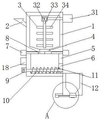
Food additive quantitative adding device with good mixing uniformity
Technical Field
The utility model relates to a food processing technology field specifically is a food additive ration that the mixture degree of consistency is good adds device.
Background
Food is an indispensable substance in our lives, food additives are needed in food processing, the food additives can not only make food color and luster good, but also prolong food storage time, and simultaneously make food taste better, although the food additives have a lot of benefits, the food additives are also harmful substances, and the use amount of the food additives is excessive to influence the body health of people, so that a food additive quantitative adding device is provided in the market, the device is used for outputting the additives quantitatively, so that the amount of the additives can be controlled, the use of workers is facilitated, at present, the mixing uniformity of common food additive quantitative adding devices is poor, different additives cannot be mixed rapidly and uniformly, the food additives cannot be added quantitatively, the quality of food processing is influenced, and the production efficiency of manufacturers is reduced, causing great inconvenience to manufacturers.
SUMMERY OF THE UTILITY MODEL
An object of the utility model is to provide a mix food additive ration that the degree of consistency is good and add device to solve the problem that proposes in the above-mentioned background art.
In order to achieve the above object, the utility model provides a following technical scheme: a food additive quantitative adding device with good mixing uniformity comprises a box body, a feeding pipe, a stirring mechanism, a first discharge port, a conveying box, a second discharge port, a first electric push rod, a first baffle, a conveying motor, a conveying rotating shaft, a spiral conveying blade, a weighing box, a third discharge port, a supporting plate, a second electric push rod, a second baffle, a pressure sensor and a controller, wherein the feeding pipe is fixedly connected to the top of the left side of the box body, the stirring mechanism is arranged in the box body, the first discharge port is formed in the middle point of the bottom of the box body, the conveying box is fixedly connected to the bottom of the box body, the second discharge port is formed in the bottom of the right side of the conveying box, the first electric push rods are fixedly connected to the tops of the left side and the right side of the conveying box, one end of each first electric push rod, close to the conveying box, penetrates through the conveying box and extends to the inside of the conveying box and is fixedly connected with the first baffle, the bottom of the left side of the conveying box is fixedly connected with a conveying motor, an output shaft of the conveying motor is fixedly connected with a conveying rotating shaft, the right end of the conveying rotating shaft sequentially penetrates through the conveying box and the second discharge port and extends to the interior of the second discharge port, the surface of the conveying rotating shaft is fixedly connected with a spiral conveying blade, the bottom of the right side of the conveying box is fixedly connected with a weighing box, a third discharge port is formed in the middle point of the bottom of the weighing box, the bottom of the left side of the weighing box is fixedly connected with a supporting plate, the left side of the bottom of the supporting plate is fixedly connected with a second electric push rod, the right end of the second electric push rod is fixedly connected with a second baffle plate, the bottom of the second baffle plate is fixedly connected with a pressure sensor, the middle point of the left side of the conveying box is fixedly, the pressure sensor is electrically connected with the controller;
rabbling mechanism includes third electric putter, agitator motor, stirring pivot and stirring rake, the top fixedly connected with third electric putter on box right side, third electric putter's left end runs through the box and extends to its inside fixedly connected with agitator motor, fixedly connected with stirring pivot on agitator motor's the output shaft, the fixed surface of stirring pivot is connected with the stirring rake, agitator motor and third electric putter respectively with controller electric connection.
Preferably, the top of the conveying box is of an open structure.
Preferably, the top of the first baffle is movably connected with the bottom of the box body.
Preferably, the top of the second baffle is movably connected with the bottom of the weighing box.
Preferably, the two first baffles are movably connected.
Compared with the prior art, the beneficial effects of the utility model are as follows:
the utility model discloses a box, feeding pipe, rabbling mechanism, first discharge gate, the delivery box, the second discharge gate, first electric putter, first baffle, conveying motor, carry the pivot, helical conveying blade, the case of weighing, the third discharge gate, a supporting plate, second electric putter, the second baffle, pressure sensor and controller mutually support, not only can carry out quick even mixed stirring to different additives, and carry out the ration of additive and add to food, the accuracy of additive has been ensured, the production efficiency and the production quality of producer have been improved.
Drawings
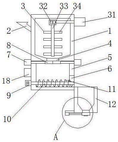
FIG. 1 is a structural section view in elevation of the present invention;
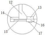
FIG. 2 is an enlarged schematic view of A of FIG. 1 according to the present invention;
fig. 3 is a schematic structural diagram of a front view of the box body of the present invention.
In the figure: the device comprises a box body 1, a feeding pipe 2, a stirring mechanism 3, a third electric push rod 31, a stirring motor 32, a stirring rotating shaft 33, a stirring paddle 34, a first discharge hole 4, a conveying box 5, a second discharge hole 6, a first electric push rod 7, a first baffle 8, a conveying motor 9, a conveying rotating shaft 10, a spiral conveying blade 11, a weighing box 12, a third discharge hole 13, a supporting plate 14, a second electric push rod 15, a second baffle 16, a pressure sensor 17 and a controller 18.
Detailed Description
The technical solutions in the embodiments of the present invention will be described clearly and completely with reference to the accompanying drawings in the embodiments of the present invention, and it is obvious that the described embodiments are only some embodiments of the present invention, not all embodiments. Based on the embodiments in the present invention, all other embodiments obtained by a person skilled in the art without creative work belong to the protection scope of the present invention.
Referring to fig. 1-3, a food additive quantitative adding device with good mixing uniformity comprises a box body 1, a feeding pipe 2, a stirring mechanism 3, a first discharge port 4, a conveying box 5, a second discharge port 6, a first electric push rod 7, a first baffle 8, a conveying motor 9, a conveying rotating shaft 10, a spiral conveying blade 11, a weighing box 12, a third discharge port 13, a support plate 14, a second electric push rod 15, a second baffle 16, a pressure sensor 17 and a controller 18, wherein the feeding pipe 2 is fixedly connected to the top of the left side of the box body 1, the stirring mechanism 3 is arranged inside the box body 1, the first discharge port 4 is arranged at the midpoint of the bottom of the box body 1, the conveying box 5 is fixedly connected to the bottom of the box body 1, the top of the conveying box 5 is of an open structure, the second discharge port 6 is arranged at the bottom of the right side of the conveying box 5, the first electric push rods 7 are fixedly connected to the tops of the left side and the right side of the conveying box 5, one end of a first electric push rod 7 close to the conveying box 5 penetrates through the conveying box 5 and extends to the inside of the conveying box and is fixedly connected with a first baffle 8, the two first baffles 8 are movably connected, the top of the first baffle 8 is movably connected with the bottom of the box body 1, the bottom of the left side of the conveying box 5 is fixedly connected with a conveying motor 9, an output shaft of the conveying motor 9 is fixedly connected with a conveying rotating shaft 10, the right end of the conveying rotating shaft 10 sequentially penetrates through the conveying box 5 and the second discharge port 6 and extends to the inside of the second discharge port 6, the surface of the conveying rotating shaft 10 is fixedly connected with a spiral conveying blade 11, the bottom of the right side of the conveying box 5 is fixedly connected with a weighing box 12, a third discharge port 13 is arranged at the midpoint of the bottom of the weighing box 12, a supporting plate 14 is fixedly connected with the bottom of the left side of the weighing box 12, a second electric push rod 15 is fixedly connected with the left end of the supporting plate 14, a second baffle 16 is fixedly connected with the right end of the second electric push rod 15, the top of the second baffle 16 is movably connected with the bottom of the weighing box 12, the bottom of the second baffle 16 is fixedly connected with a pressure sensor 17, the middle point of the left side of the conveying box 5 is fixedly connected with a controller 18, the first electric push rod 7 and the second electric push rod 15 are respectively electrically connected with the controller 18, and the pressure sensor 17 is electrically connected with the controller 18.
Rabbling mechanism 3 includes third electric putter 31, agitator motor 32, stirring pivot 33 and stirring rake 34, the top fixedly connected with third electric putter 31 on box 1 right side, the left end of third electric putter 31 runs through box 1 and extends to its inside fixedly connected with agitator motor 32, fixedly connected with stirring pivot 33 on agitator motor 32's the output shaft, the fixed surface of stirring pivot 33 is connected with stirring rake 34, agitator motor 32 and third electric putter 31 respectively with controller 18 electric connection.
When the additive weighing device is used, additives are poured into the box body 1 through the feeding pipe 2, the stirring motor 32 is started, the stirring paddle 34 is driven to rotate by the stirring motor 32 so as to stir the additives, meanwhile, the third electric push rod 31 is controlled by the controller 18 to drive the stirring motor 32 to do continuous left-right reciprocating motion, so that the stirring range of the stirring paddle 34 is improved, the additives can be mixed more uniformly and rapidly, after the stirring is finished, the first electric push rod 7 is controlled by the controller 18 to drive the first baffle 8 to move outwards, so that the first baffle 8 is separated from the first discharge hole 4, the additives in the box body 1 fall into the conveying box 5, then the conveying motor 9 is controlled by the controller 18 to be started, so that the conveying rotating shaft 10 and the spiral conveying blade 11 are driven by the conveying motor 9 to rotate, and the additives are conveyed into the weighing box 12 by the spiral conveying blade 11, when the pressure sensor 17 senses that the weight of the additive reaches a specified weight, a signal is transmitted to the controller 18, so that the controller 18 turns off the transmission motor 9, then the controller 18 controls the second electric push rod 15 to drive the second baffle 16 to move towards the left side, so that the second baffle 16 is separated from the third discharge hole 13, so that the additive flows out of the third discharge hole 13, the additive is quantitatively added to the food, then the controller 18 controls the second electric push rod 15 to drive the second baffle 16 to reset, and then the steps are repeated continuously, so that continuous operation can be achieved.
The utility model discloses circuit and control that relate to are prior art, do not carry out too much repetition here.
Although embodiments of the present invention have been shown and described, it will be appreciated by those skilled in the art that changes, modifications, substitutions and alterations can be made in these embodiments without departing from the principles and spirit of the invention, the scope of which is defined in the appended claims and their equivalents.