CN213909213U - Assembly type mounting structure of cabinet frame - Google Patents
Assembly type mounting structure of cabinet frame Download PDFInfo
- Publication number
- CN213909213U CN213909213U CN202022342657.XU CN202022342657U CN213909213U CN 213909213 U CN213909213 U CN 213909213U CN 202022342657 U CN202022342657 U CN 202022342657U CN 213909213 U CN213909213 U CN 213909213U
- Authority
- CN
- China
- Prior art keywords
- montant
- mounting structure
- cabinet frame
- threaded
- vertical
- Prior art date
- Legal status (The legal status is an assumption and is not a legal conclusion. Google has not performed a legal analysis and makes no representation as to the accuracy of the status listed.)
- Expired - Fee Related
Links
Images



Landscapes
- Furniture Connections (AREA)
Abstract
The utility model belongs to the technical field of cabinet frame, and an assembled mounting structure of cabinet frame is disclosed, which comprises a base frame, the equal swing joint in both sides at chassis top has the montant, the quantity of montant is four, four equal swing joint has the overhead board between the top of montant, the top swing joint of overhead board has the roof, perpendicular mouth has been seted up at the top of montant, the inside activity of erecting the mouth has cup jointed the riser, the top of riser and the bottom fixed connection of overhead board. The utility model discloses a set up screw hole, first threaded rod, right angle frame and screw, because the cooperation between screw hole and the first threaded rod, will play the fixed action between montant, overhead board and the roof, and because the cooperation between right angle frame and the screw, will play good fixed action between chassis and the montant, easy operation just expends the time weak point, and the staff's of being convenient for operation has consequently increased this cupboard frame construction's practicality.
Description
Technical Field
The utility model belongs to the technical field of the cupboard frame, specifically be an assembled mounting structure of cupboard frame.
Background
The cabinet is a platform for storing kitchenware and cooking operation in a kitchen, is generally matched with colors with higher lightness, and consists of five major parts, namely a cabinet body, a door plate, hardware, a table board and an electric appliance.
At present, when the staff installs the cupboard in the kitchen, at first need build the frame of cupboard and form, and current cupboard frame is in the in-process of building with the installation, has following defect:
first, current cabinet frame is when building, generally all adopts welding or threaded connection's mode to go on, for welded mode, will lead to this frame later stage can't dismantle, and traditional threaded connection mode, and the operation is not only loaded down with trivial details but also consumes time long to the use that gives the staff has brought inconvenience.
Second, the existing cabinet frame often results in a part of the screw structure being exposed after installation when using the screw connection, thereby affecting the overall beauty of the cabinet.
Third, the top of the existing cabinet frame is provided with a top plate for users to place kitchen supplies at ordinary times, however, the top plate is broken due to collision in the actual use process, which causes inconvenience for workers to detach the top plate.
SUMMERY OF THE UTILITY MODEL
An object of the utility model is to provide an assembled mounting structure of cupboard frame to solve the problem that proposes among the above-mentioned background art.
In order to achieve the above object, the present invention provides the following technical solutions: an assembled mounting structure of a cabinet frame comprises an underframe, wherein vertical rods are movably connected to two sides of the top of the underframe, the number of the vertical rods is four, an upper plate is movably connected between the tops of the four vertical rods, a top plate is movably connected to the top of the upper plate, vertical ports are formed in the tops of the vertical rods, vertical blocks are movably sleeved in the vertical ports, the top ends of the vertical blocks are fixedly connected with the bottom of the upper plate, threaded holes are formed in the vertical blocks, first threaded rods are sleeved with internal threads of the threaded holes, one ends of the first threaded rods penetrate through the vertical rods and extend into the inner walls of the vertical rods, the other ends of the first threaded rods are positioned on the right sides of the vertical rods, right-angle brackets are movably connected between the tops of the underframe and the right sides of the vertical rods, screws are sleeved with the internal threads of the right-angle brackets, the number of the screws is two, the other ends of the two screws respectively penetrate through the underframe and the vertical rod and extend into the inner walls of the underframe and the vertical rod.
Preferably, first locating port has all been seted up to the both sides at chassis top, first locating shaft has been cup jointed in the inside activity of first locating port, the top of first locating shaft and the bottom fixed connection of montant because the cooperation between first locating port and the first locating shaft, will play good location effect to the montant, and then made things convenient for the subsequent installation of staff.
Preferably, the curb plate has been cup jointed in the activity between the montant, the bottom of curb plate and the top swing joint of chassis, the top of curb plate and the bottom swing joint of overhead board, the constant head tank has all been seted up to the both sides of curb plate top and bottom, the locating piece has been cup jointed in the inside activity of constant head tank, the quantity of locating piece is four, four two of locating piece horizontal direction are a set of, two sets of the other end of locating piece respectively with the bottom of overhead board and the top fixed connection of chassis, because the cooperation between constant head tank and the locating piece, will realize the fixed action to the curb plate has been avoided the curb plate to take place the position and has been removed.
Preferably, the second location mouth has all been seted up to the both sides of roof bottom, the top fixed mounting of overhead board has the second location axle that is located the inside second location mouth, the surface of second location axle and the inner wall swing joint of second location mouth will play good positioning action to the roof because the cooperation between second location mouth and the second location axle to it is fixed to be convenient for the staff follow-up to install the roof.
Preferably, the equal fixed mounting in both sides of overhead board bottom has the dog, the first screw thread mouth that is located the dog right side is seted up to the bottom of overhead board, the second screw thread mouth that is located first screw thread mouth right side is seted up to the bottom of overhead board, the internal orifice that is located first screw thread mouth right side is seted up to the inside of overhead board, the top chamber that is located the internal orifice upper left side is seted up to the inside of roof, the bayonet socket that is located top chamber right side is seted up to the inside of roof, because the cooperation between dog and the first screw thread mouth, will realize the location effect to fly leaf and second threaded rod for the inside of screw in to first screw thread mouth that the piece can be smooth is drawn, thereby realizes the location effect to fly leaf, motion piece and fixture block.
Preferably, the inside fixed mounting of internal orifice has the horizontal pole, the movable block has been cup jointed in the surface activity of horizontal pole, the top fixed mounting of movable block has the motion piece that is located the intracavity portion, one side fixed mounting of motion piece has the fixture block that is located the bayonet socket inside, because the cooperation between bayonet socket and the fixture block, will realize the fixed action to the roof, has prevented that the roof from breaking away from the top of overhead board.
Preferably, the bottom fixed mounting of movable block has the fly leaf that is located the overhead board outside, the top of fly leaf and the bottom swing joint of overhead board, the right side fixed mounting of fly leaf bottom has the piece of drawing, the internal thread of fly leaf has cup jointed and is located the left second threaded rod of the piece of drawing, the bottom of second threaded rod runs through the fly leaf and extends to the below of fly leaf, owing to draw the design of piece to make the staff be convenient for to draw motion piece and fixture block and wholly move about, and the screw thread of second threaded rod surface and the inside screw thread looks adaptation of first screw thread mouth, thereby make the inside that the second threaded rod can screw in to first screw thread mouth.
Preferably, a chamber has all been seted up to the inside of two corners at curb plate top, the right-hand member of first threaded rod is located the inside in chamber, because the design in chamber, will accomodate the right-hand member of first threaded rod and hide.
Preferably, the draw-in groove has all been seted up to the inside of two corners in curb plate bottom, the right angle frame is located the inside of draw-in groove, because the design of draw-in groove, will accomodate the right angle frame to make chassis and montant whole look more pleasing to the eye.
The utility model has the advantages as follows:
1. the utility model discloses a set up screw hole, first threaded rod, right angle frame and screw, because the cooperation between screw hole and the first threaded rod, will play the fixed action between montant, overhead board and the roof, and because the cooperation between right angle frame and the screw, will play good fixed action between chassis and the montant, easy operation just expends the time weak point, and the staff's of being convenient for operation has consequently increased this cupboard frame construction's practicality.
2. The utility model discloses a set up draw-in groove and top chamber, because the design in top chamber, will accomodate the outside one end of first threaded rod and hide, and because the design of draw-in groove, will realize accomodating of right-angle frame and screw to make the side of chassis and montant seem more pleasing to the eye, consequently further increased this cupboard frame construction's practicality.
3. The utility model discloses a set up dog, first screw thread mouth, bayonet socket, fixture block and second threaded rod, because the design of dog will fix a position the fly leaf, the inside that the second threaded rod can screw in to first screw thread mouth this moment, the fixture block will break away from the inside of bayonet socket simultaneously to remove the fixed action to the roof, made things convenient for the staff to replace the roof, consequently improved this cupboard frame construction's practicality.
Drawings
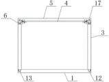
Fig. 1 is a schematic structural view of the present invention;
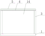
fig. 2 is a schematic side view of the present invention;
FIG. 3 is a schematic cross-sectional view of the side of the present invention;
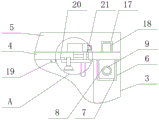
FIG. 4 is a schematic view of the internal structure of the upper plate and the top plate of the present invention;
FIG. 5 is a schematic view of the internal structure of the vertical port of the present invention;
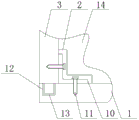
fig. 6 is a schematic view of the internal structure of the slot of the present invention;
fig. 7 is a schematic view of the local enlarged structure at a position of the present invention.
In the figure: 1. a chassis; 2. a card slot; 3. a vertical rod; 4. a board is arranged on the frame; 5. a top plate; 6. erecting a port; 7. a vertical block; 8. a threaded hole; 9. a first threaded rod; 10. a right-angle frame; 11. a screw; 12. a first positioning port; 13. a first positioning shaft; 14. a side plate; 15. positioning a groove; 16. positioning blocks; 17. a second positioning port; 18. a second positioning shaft; 19. a stopper; 20. a first threaded port; 21. an inner opening; 22. a top chamber; 23. a cross bar; 24. a movable block; 25. a bayonet; 26. a motion block; 27. a clamping block; 28. a second threaded port; 29. a movable plate; 30. a second threaded rod; 31. pulling the block; 32. a top cavity.
Detailed Description
The technical solutions in the embodiments of the present invention will be described clearly and completely with reference to the accompanying drawings in the embodiments of the present invention, and it is obvious that the described embodiments are only some embodiments of the present invention, not all embodiments. Based on the embodiments in the present invention, all other embodiments obtained by a person skilled in the art without creative work belong to the protection scope of the present invention.
As shown in figures 1 to 7, in the embodiment of the present invention, an assembly type mounting structure of a cabinet frame comprises a bottom frame 1, wherein two sides of the top of the bottom frame 1 are movably connected with four vertical rods 3, an upper plate 4 is movably connected between the tops of the four vertical rods 3, the top of the upper plate 4 is movably connected with a top plate 5, the top of each vertical rod 3 is provided with a vertical port 6, a vertical block 7 is movably sleeved on the inside of each vertical port 6, the top end of each vertical block 7 is fixedly connected with the bottom of the upper plate 4, a threaded hole 8 is formed inside each vertical block 7, a first threaded rod 9 is sleeved on the internal thread of each threaded hole 8, one end of each first threaded rod 9 penetrates through the corresponding vertical rod 3 and extends into the inner wall of the corresponding vertical rod 3, the other end of the corresponding first threaded rod 9 is positioned on the right side of the corresponding vertical rod 3, a right-angle frame 10 is movably connected between the top of the bottom frame 1 and the right side of the corresponding vertical rod 3, a right-angle screw 11 is sleeved on the internal thread of the right-angle frame 10, the number of the screws 11 is two, and the other ends of the two screws 11 respectively penetrate through the underframe 1 and the vertical rod 3 and extend into the inner walls of the underframe 1 and the vertical rod 3.
Wherein, first locating port 12 has all been seted up to the both sides at 1 top of chassis, and first locating shaft 13 has been cup jointed in the inside activity of first locating port 12, the top of first locating shaft 13 and the bottom fixed connection of montant 3, because the cooperation between first locating port 12 and the first locating shaft 13 will play good location effect to montant 3, and then made things convenient for the subsequent installation operation of staff.
Wherein, curb plate 14 has been cup jointed in the activity between montant 3, curb plate 14's bottom and chassis 1's top swing joint, curb plate 14's top and the bottom swing joint of overhead board 4, constant head tank 15 has all been seted up to the both sides of curb plate 14 top and bottom, locating piece 16 has been cup jointed in the inside activity of constant head tank 15, locating piece 16's quantity is four, two of four locating piece 16 horizontal direction are a set of, two sets of locating piece 16's the other end respectively with the bottom of overhead board 4 and chassis 1's top fixed connection, because cooperation between constant head tank 15 and the locating piece 16, will realize the fixed action to curb plate 14, thereby curb plate 14 has been avoided taking place the position and has been removed.
Wherein, second location mouth 17 has all been seted up to the both sides of roof 5 bottom, and the top fixed mounting of overhead board 4 has the second location axle 18 that is located second location mouth 17 inside, and the surface of second location axle 18 and the inner wall swing joint of second location mouth 17 will play good positioning action to roof 5 because the cooperation between second location mouth 17 and the second location axle 18 to be convenient for the staff is follow-up to install fixedly roof 5.
Wherein, the equal fixed mounting in both sides of overhead board 4 bottom has dog 19, the first screw thread mouth 20 that is located the dog 19 right side is seted up to the bottom of overhead board 4, the second screw thread mouth 28 that is located first screw thread mouth 20 right side is seted up to the bottom of overhead board 4, the internal orifice 21 that is located first screw thread mouth 20 right side is seted up to the inside of overhead board 4, the top chamber 22 that is located the upper left of internal orifice 21 is seted up to the inside of roof 5, the bayonet socket 25 that is located top chamber 22 right side is seted up to the inside of roof 5, because the cooperation between dog 19 and the first screw thread mouth 20, will realize the location effect to fly leaf 29 and second threaded rod 30, make the inside of screw in to first screw thread mouth 20 that draws piece 31 can be smooth, thereby realize the location effect to fly leaf 29, motion block 26 and fixture block 27.
Wherein, the inside fixed mounting of interior mouth 21 has horizontal pole 23, and the surface activity of horizontal pole 23 has cup jointed movable block 24, and movable block 24's top fixed mounting has the motion piece 26 that is located the inside of top chamber 22, and one side fixed mounting of motion piece 26 has the fixture block 27 that is located bayonet 25 inside, because the cooperation between bayonet 25 and the fixture block 27, will realize the fixed action to roof 5, has prevented that roof 5 from breaking away from the top of overhead board 4.
Wherein, the bottom fixed mounting of movable block 24 has the fly leaf 29 that is located the outside of overhead board 4, the top of fly leaf 29 and the bottom swing joint of overhead board 4, the right side fixed mounting of fly leaf 29 bottom has the piece of drawing 31, the internal thread of fly leaf 29 cup joints the second threaded rod 30 that is located the left side of the piece of drawing 31, the bottom of second threaded rod 30 runs through fly leaf 29 and extends to the below of fly leaf 29, owing to the design of the piece of drawing 31, thereby make the staff be convenient for pull motion block 26 and fixture block 27 and wholly move about, and the screw thread of second threaded rod 30 surface and the inside screw thread looks adaptation of first screw thread mouth 20, thereby make second threaded rod 30 can screw in to the inside of first screw thread mouth 20.
Wherein, top chamber 32 has all been seted up to the inside of two corners in curb plate 14 top, and the right-hand member of first threaded rod 9 is located the inside in top chamber 32, because the design in top chamber 32 will accomodate the right-hand member of first threaded rod 9 and hide.
Wherein, draw-in groove 2 has all been seted up to the inside of two corners in curb plate 14 bottom, and right angle frame 10 is located the inside of draw-in groove 2, because the design of draw-in groove 2 will accomodate right angle frame 10 to make chassis 1 and montant 3 whole look more pleasing to the eye.
The working principle and the using process are as follows: when the cabinet frame is assembled, firstly, a worker inserts a first positioning shaft 13 at the bottom of a vertical rod 3 into a first positioning opening 12, then attaches the bottom of a right-angle frame 10 to the top of an underframe 1, and attaches the left side of the right-angle frame to the right side of the vertical rod 3, then screws the right-angle frame 10 and the vertical rod 3 into the underframe 1 and the vertical rod 3 respectively by using two screws 11, so as to fix the underframe 1 and the vertical rod 3, then puts a side plate 14 between the two vertical rods 3, and enables a positioning block 16 at the top of the underframe 1 to enter into a positioning groove 15, meanwhile, the right-angle frame 10 and the screws 11 are located inside a clamping groove 2, then the worker can put an upper plate 4 to the top of the vertical rod 3, then enables a vertical block 7 to enter into the inside of a vertical opening 6, and then screws a first threaded rod 9 into a threaded hole 8, so as to fix the upper plate 4 and a top plate 5, when the staff need dismantle roof 5, the staff at first rotates second threaded rod 30 for the top of second threaded rod 30 breaks away from the inside of second screw thread mouth 28, then pulls and draws piece 31, makes activity piece 24 drive motion piece 26 and fixture block 27 motion, and finally movable plate 29 will be blockked by dog 19, then the staff screws in second threaded rod 30 to the inside of first screw thread mouth 20 and then forms fixed action to movable plate 29, fixture block 27 will break away from the inside of bayonet 25 this moment, later the staff can pull roof 5, make it separate from the top of overhead plate 4.
It is noted that, herein, relational terms such as first and second, and the like may be used solely to distinguish one entity or action from another entity or action without necessarily requiring or implying any actual such relationship or order between such entities or actions. Also, the terms "comprises," "comprising," or any other variation thereof, are intended to cover a non-exclusive inclusion, such that a process, method, article, or apparatus that comprises a list of elements does not include only those elements but may include other elements not expressly listed or inherent to such process, method, article, or apparatus.
Although embodiments of the present invention have been shown and described, it will be appreciated by those skilled in the art that changes, modifications, substitutions and alterations can be made in these embodiments without departing from the principles and spirit of the invention, the scope of which is defined in the appended claims and their equivalents.
Claims (9)
1. An assembled mounting structure of cabinet frame, includes chassis (1), its characterized in that: both sides of the top of the underframe (1) are movably connected with vertical rods (3), the number of the vertical rods (3) is four, an upper plate (4) is movably connected between the tops of the four vertical rods (3), the top of the upper plate (4) is movably connected with a top plate (5), vertical ports (6) are formed in the tops of the vertical rods (3), vertical blocks (7) are movably sleeved in the vertical ports (6), the top ends of the vertical blocks (7) are fixedly connected with the bottoms of the upper plate (4), threaded holes (8) are formed in the vertical blocks (7), first threaded rods (9) are sleeved in internal threads of the threaded holes (8), one ends of the first threaded rods (9) penetrate through the vertical rods (3) and extend into the inner walls of the vertical rods (3), the other ends of the first threaded rods (9) are positioned on the right sides of the vertical rods (3), right-angle brackets (10) are movably connected between the tops of the underframe (1) and the right sides of the vertical rods (3), the internal thread of right-angle frame (10) has cup jointed screw (11), the quantity of screw (11) is two, two the other end of screw (11) runs through chassis (1) and montant (3) respectively and extends to in the inner wall of chassis (1) and montant (3).
2. The assembly type mounting structure of a cabinet frame as claimed in claim 1, wherein: first locating port (12) have all been seted up to the both sides at chassis (1) top, first locating shaft (13) have been cup jointed in the inside activity of first locating port (12), the top of first locating shaft (13) and the bottom fixed connection of montant (3).
3. The assembly type mounting structure of a cabinet frame as claimed in claim 1, wherein: curb plate (14) have been cup jointed in the activity between montant (3), the top swing joint of the bottom of curb plate (14) and chassis (1), the top of curb plate (14) and the bottom swing joint of overhead board (4), constant head tank (15) have all been seted up to the both sides of curb plate (14) top and bottom, locating piece (16) have been cup jointed in the inside activity of constant head tank (15), the quantity of locating piece (16) is four, four two of locating piece (16) horizontal direction are a set of, and are two sets of the other end of locating piece (16) respectively with the bottom of overhead board (4) and the top fixed connection of chassis (1).
4. The assembly type mounting structure of a cabinet frame as claimed in claim 1, wherein: second location mouth (17) have all been seted up to the both sides of roof (5) bottom, the top fixed mounting of overhead board (4) has second location axle (18) that are located second location mouth (17) inside, the surface of second location axle (18) and the inner wall swing joint of second location mouth (17).
5. The assembly type mounting structure of a cabinet frame as claimed in claim 1, wherein: the improved structure of the screw driver is characterized in that a stop block (19) is fixedly mounted on two sides of the bottom of the upper plate (4), a first threaded opening (20) located on the right side of the stop block (19) is formed in the bottom of the upper plate (4), a second threaded opening (28) located on the right side of the first threaded opening (20) is formed in the bottom of the upper plate (4), an inner opening (21) located on the right side of the first threaded opening (20) is formed in the inner portion of the upper plate (4), a top cavity (22) located above the left of the inner opening (21) is formed in the inner portion of the top plate (5), and a bayonet (25) located on the right side of the top cavity (22) is formed in the inner portion of the top plate (5).
6. The assembly type mounting structure of a cabinet frame as claimed in claim 5, wherein: the inside fixed mounting of interior mouth (21) has horizontal pole (23), movable block (24) have been cup jointed in the surface activity of horizontal pole (23), the top fixed mounting of movable block (24) has motion block (26) that are located top chamber (22) inside, one side fixed mounting of motion block (26) has fixture block (27) that are located bayonet socket (25) inside.
7. The assembly type mounting structure of a cabinet frame as claimed in claim 6, wherein: the bottom fixed mounting of movable block (24) has and is located the outside fly leaf (29) of overhead board (4), the top of fly leaf (29) and the bottom swing joint of overhead board (4), the right side fixed mounting of fly leaf (29) bottom has and draws piece (31), the internal thread of fly leaf (29) has been cup jointed and is located the second threaded rod (30) that draw piece (31) left, the bottom of second threaded rod (30) runs through fly leaf (29) and extends to the below of fly leaf (29).
8. The assembly type mounting structure of a cabinet frame as claimed in claim 3, wherein: top chamber (32) have all been seted up to the inside of two corners at curb plate (14) top, the right-hand member of first threaded rod (9) is located the inside in top chamber (32).
9. The assembly type mounting structure of a cabinet frame as claimed in claim 3, wherein: draw-in groove (2) have all been seted up to the inside of two corners in curb plate (14) bottom, right angle frame (10) are located the inside of draw-in groove (2).
Priority Applications (1)
| Application Number | Priority Date | Filing Date | Title |
|---|---|---|---|
| CN202022342657.XU CN213909213U (en) | 2020-10-20 | 2020-10-20 | Assembly type mounting structure of cabinet frame |
Applications Claiming Priority (1)
| Application Number | Priority Date | Filing Date | Title |
|---|---|---|---|
| CN202022342657.XU CN213909213U (en) | 2020-10-20 | 2020-10-20 | Assembly type mounting structure of cabinet frame |
Publications (1)
| Publication Number | Publication Date |
|---|---|
| CN213909213U true CN213909213U (en) | 2021-08-10 |
Family
ID=77163383
Family Applications (1)
| Application Number | Title | Priority Date | Filing Date |
|---|---|---|---|
| CN202022342657.XU Expired - Fee Related CN213909213U (en) | 2020-10-20 | 2020-10-20 | Assembly type mounting structure of cabinet frame |
Country Status (1)
| Country | Link |
|---|---|
| CN (1) | CN213909213U (en) |
Cited By (1)
| Publication number | Priority date | Publication date | Assignee | Title |
|---|---|---|---|---|
| CN112137312A (en) * | 2020-10-20 | 2020-12-29 | 金螳螂精装科技(苏州)有限公司 | Assembly type mounting structure of cabinet frame |
-
2020
- 2020-10-20 CN CN202022342657.XU patent/CN213909213U/en not_active Expired - Fee Related
Cited By (1)
| Publication number | Priority date | Publication date | Assignee | Title |
|---|---|---|---|---|
| CN112137312A (en) * | 2020-10-20 | 2020-12-29 | 金螳螂精装科技(苏州)有限公司 | Assembly type mounting structure of cabinet frame |
Similar Documents
| Publication | Publication Date | Title |
|---|---|---|
| CN112137312A (en) | Assembly type mounting structure of cabinet frame | |
| CN217537454U (en) | Light fretwork aluminum plate curtain | |
| CN218279014U (en) | Combined clothes and hat cabinet convenient to disassemble and assemble | |
| CN217218843U (en) | Shower room frame and simple installation structure thereof | |
| CN213344816U (en) | Easy dismounting's large capacity wardrobe | |
| CN213909222U (en) | Modular chinampa cabinet | |
| CN212227148U (en) | Smoke ventilator convenient to clearance | |
| CN212405807U (en) | Assembled wall decorative board mounting structure | |
| CN214238633U (en) | Planer for furniture production | |
| CN213882446U (en) | Assembled bathroom wall-hung cabinet semi-embedded in wall | |
| CN220546007U (en) | Suspension type cupboard convenient to clean | |
| CN205949408U (en) | Fast assembly's wind leaching rooms | |
| CN210140909U (en) | Sunshine room with extend platform | |
| CN212815115U (en) | Reinforced structure of built-in drawer of wardrobe | |
| CN208435125U (en) | A kind of rotatable contact clothing cabinet mirror face | |
| CN214059583U (en) | Elevator car roof fixing structure | |
| CN211323690U (en) | Smart Home Wardrobe | |
| CN219422497U (en) | Wine cabinet handle | |
| CN215630883U (en) | Isolation curtain wall for building intelligent installation engineering | |
| CN216932697U (en) | Intelligent furniture convenient to clean | |
| CN211408113U (en) | Titanium-plated stainless steel combined wardrobe convenient to install | |
| CN218439002U (en) | Easily install sound insulation door and window toughened glass | |
| CN220001170U (en) | Medical diagnosis table for assembled wall | |
| CN218571788U (en) | Hanging bracket for kitchen cabinet | |
| CN211286003U (en) | Scalable gallows is used in support of intelligence people's house case room |
Legal Events
| Date | Code | Title | Description |
|---|---|---|---|
| GR01 | Patent grant | ||
| GR01 | Patent grant | ||
| CF01 | Termination of patent right due to non-payment of annual fee | ||
| CF01 | Termination of patent right due to non-payment of annual fee |
Granted publication date: 20210810 |