Disclosure of Invention
The utility model aims at solving the defects existing in the prior art and providing mechanical punching equipment.
In order to achieve the above purpose, the utility model adopts the following technical scheme: the utility model provides a mechanical punching equipment, includes the processing platform, the last fixed surface symmetry fixed mounting of processing platform has the backup pad, and is two sets of the last fixed surface of backup pad installs the roof, the last fixed surface of roof installs the motor, the output of motor rotates and is connected with the drilling rod, the upper surface of processing platform is provided with clearance mechanism.
Cleaning mechanism includes the fixing base, the last surface symmetry fixed mounting of processing platform has the fixing base, logical groove has been seted up to the surface of fixing base, the spacing groove has been seted up to the inner wall symmetry that leads to the groove, the inner wall sliding connection who leads to the groove has the brush board, fixed mounting has reset spring between the inner wall of brush board and logical groove, reset spring's a lateral symmetry fixed mounting is kept away from to the brush board has the connecting rod, one lateral symmetry sliding connection that the brush board was kept away from to the processing platform has the inserted bar, and is two sets of the one end fixed mounting that the processing platform was kept away from to the inserted bar has the collection box, collect one side fixed mounting that the inserted bar was kept away from to the box and have the handle.
Preferably, the outer surface of the brush plate is symmetrically and fixedly provided with limiting blocks, and the limiting grooves are matched with the limiting blocks in size.
Preferably, the machining table is symmetrically provided with connecting holes at one side close to the inserting rod, and the inserting rod is connected with the inner wall of the connecting holes in a sliding manner.
Preferably, two sets of the opposite sides of backup pad symmetry fixed mounting have the pneumatic cylinder, the one end fixed mounting that the backup pad was kept away from to the pneumatic cylinder has the clamp splice.
Preferably, one side of the support plate close to the drill rod is provided with a stabilizing mechanism, the stabilizing mechanism comprises a sliding groove, one side of the support plate close to the drill rod is provided with the sliding groove, the inner wall of the sliding groove is symmetrically provided with clamping grooves, the inner wall of the sliding groove is connected with an ejector rod in a sliding mode, the outer surface of the ejector rod is symmetrically and fixedly provided with clamping blocks, the outer surface of the drill rod rotates to be provided with a connecting ring, and one end, far away from the sliding groove, of the ejector rod is fixedly connected with the outer surface of the connecting ring.
Preferably, the fixture block is connected with the inner wall of the clamping groove in a sliding mode, and a fixing ring is sleeved on the outer surface of one end, close to the connecting ring, of the drill rod.
Compared with the prior art, the utility model discloses an advantage lies in with positive effect:
1. in the utility model, when the worker uses the punching equipment, firstly, the hydraulic cylinder is opened, the part is fixed by the clamping block, then the motor is started, the motor drives the drill rod to punch, after the punching is finished, the worker holds the connecting rod, then pulls the connecting rod, under the action of the limiting block and the limiting groove, the connecting rod can drive the brush board to move in the through groove, simultaneously, the brush board can stretch the reset spring, the brush board can sweep the scraps on the surface of the processing table, when the brush board moves to the final position, the scraps can directly fall into the collecting box, at the moment, the worker loosens the connecting rod, the reset spring rebounds to fully fill the brush board, the brush board is brought back to the original position, when the collecting box is used, the worker can hold the handle, the collecting box is taken out from the processing table, the scraps are intensively treated, after the treatment, the cooperation effect of the inserting rod and the connecting hole is utilized, the collecting box is inserted back into the processing table, through setting up this clearance mechanism, not only alleviateed staff's intensity of labour greatly, when guaranteeing production efficiency moreover, avoided the staff to carry out the condition emergence of secondary clearance, saved a large amount of time, improved efficiency.
2. In the utility model, when the drill rod is used for drilling, the vibration is generated at the time, the drill rod is shaken, the vibration is directly transmitted to the connecting ring on the surface of the drill rod and then transmitted to the ejector rod through the connecting ring, the ejector rod directly extrudes the supporting plate under the action of the vibration, the supporting plate generates a reaction force, so as to offset the vibration of the drill rod and ensure that the drill rod is more stable in the drilling process, and simultaneously, under the action of the clamping groove and the clamping block, the ejector rod moves downwards along with the movement of the drill rod, thereby keeping the drill rod at the same position without moving, ensuring the stability of the drill rod, and through the arrangement of the stabilizing mechanism, the stability of the drill rod during working can be effectively improved, the situation that machining errors are increased due to vibration of the drill rod is prevented, the accuracy of equipment is improved, and therefore the machining quality of parts is guaranteed.
Detailed Description
In order to make the objects, technical solutions and advantages of the present invention more clearly understood, the present invention is further described in detail below with reference to the accompanying drawings and embodiments. It should be understood that the specific embodiments described herein are merely illustrative of the invention and are not intended to limit the invention.
In the description of the present invention, it is to be understood that the terms "length", "width", "upper", "lower", "front", "rear", "left", "right", "vertical", "horizontal", "top", "bottom", "inner", "outer", and the like indicate orientations or positional relationships based on those shown in the drawings, and are merely for convenience of description and simplicity of description, and do not indicate or imply that the device or element being referred to must have a particular orientation, be constructed and operated in a particular orientation, and thus, should not be construed as limiting the present invention. In addition, in the description of the present invention, "a plurality" means two or more unless specifically limited otherwise.
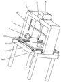
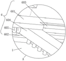
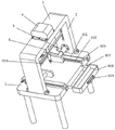
Referring to fig. 1-6, the present invention provides a technical solution: a mechanical punching device comprises a processing table 1, wherein supporting plates 2 are symmetrically and fixedly installed on the upper surface of the processing table 1, a top plate 3 is fixedly installed on the upper surfaces of two groups of supporting plates 2, a motor 4 is fixedly installed on the upper surface of the top plate 3, an output end of the motor 4 is rotatably connected with a drill rod 5, a cleaning mechanism 6 is arranged on the upper surface of the processing table 1, the cleaning mechanism 6 comprises a fixed seat 601, a fixed seat 601 is symmetrically and fixedly installed on the upper surface of the processing table 1, a through groove 602 is formed in the outer surface of the fixed seat 601, a limiting groove 603 is symmetrically formed in the inner wall of the through groove 602, a brush plate 604 is slidably connected to the inner wall of the through groove 602, a return spring 605 is fixedly installed between the brush plate 604 and the inner wall of the through groove 602, a connecting rod 606 is symmetrically and fixedly installed on one side of the brush plate 604, an inserting rod 607 is symmetrically and slidably connected to one side of the processing table 1, and a collecting box 608 is fixedly installed on one end of the two groups of the inserting rod 607 far away from the processing table 1, a handle 609 is fixedly mounted on the side of the collection box 608 remote from the bayonet 607.
In this embodiment: when a worker uses the punching equipment, firstly, the hydraulic cylinder 7 is opened, the clamping block is used for fixing parts, then the motor 4 is started, the motor 4 drives the drill rod 5 to punch, after punching is completed, the worker holds the connecting rod 606, then pulls the connecting rod 606, the connecting rod 606 can drive the brush board 604 to move in the through groove 602 under the action of the limiting block and the limiting groove 603, meanwhile, the brush board 604 can stretch the return spring 605, the brush board 604 can sweep waste scraps on the surface of the processing table 1, when the brush board moves to a final position, the waste scraps can directly fall into the collecting box 608, at the moment, the worker releases the connecting rod 606, the return spring 605 rebounds to bring the brush board 604 back to the original position, when the collecting box 608 is full, the worker can hold the handle 609 to draw the collecting box 608 out of the processing table 1, the waste scraps are intensively treated, and after treatment, the cooperation effect of the inserting rod 607 and the connecting hole is utilized, insert back to the processing platform 1 with collecting box 608 can, through setting up this clearance mechanism 6, not only alleviateed staff's intensity of labour greatly, when guaranteeing production efficiency, avoided the staff to carry out the condition emergence of secondary clearance moreover, saved a large amount of time, improved efficiency.
Specifically, the outer surface of the brush plate 604 is symmetrically and fixedly provided with a limiting block, and the limiting groove 603 is matched with the limiting block in size.
In this embodiment: through the action of the limiting groove 603 and the limiting block, the brush plate 604 can be ensured not to be separated from the through groove 602 in the moving process.
Specifically, connecting holes are symmetrically formed in one side, close to the inserting rod 607, of the machining table 1, and the inserting rod 607 is connected with the inner wall of the connecting hole in a sliding mode.
In this embodiment: the cooperation of the insertion rod 607 and the connection hole facilitates the removal and insertion of the collection box 608 by the worker.
Specifically, two sets of backup pad 2 opposite one side symmetry fixed mounting have pneumatic cylinder 7, and the one end fixed mounting that backup pad 2 was kept away from to pneumatic cylinder 7 has the clamp splice.
In this embodiment: the clamping blocks are driven by the hydraulic cylinders 7, so that the parts can be clamped more tightly in the punching process, and the punching process cannot be influenced.
Specifically, one side of the support plate 2 close to the drill rod 5 is provided with a stabilizing mechanism 8, the stabilizing mechanism 8 comprises a sliding groove 801, one side of the support plate 2 close to the drill rod 5 is provided with the sliding groove 801, the inner wall of the sliding groove 801 is symmetrically provided with clamping grooves 802, the inner wall of the sliding groove 801 is slidably connected with a push rod 803, the outer surface of the push rod 803 is symmetrically and fixedly provided with a clamping block 804, the outer surface of the drill rod 5 rotates to form a connecting ring 805, and one end of the push rod 803, far away from the sliding groove 801, is fixedly connected with the outer surface of the connecting ring 805.
In this embodiment: when the drill rod 5 is used for drilling, vibration is generated at the moment, the drill rod 5 is shaken, the vibration is directly transmitted to the connecting ring 805 on the surface of the drill rod 5 and then transmitted to the ejector rod 803 through the connecting ring 805, the ejector rod 803 directly extrudes the support plate 2 due to the vibration, a reaction force is generated by the support plate 2, so that the vibration of the drill rod 5 is counteracted, the drill rod 5 is more stable in the drilling process, meanwhile, under the action of the clamping groove 802 and the clamping block 804, the ejector rod 803 moves downwards along with the movement of the drill rod 5, so that the drill rod 5 is kept at the same position without moving, the stability of the drill rod 5 is ensured, the stability of the drill rod 5 in the working process can be effectively improved through the arrangement of the stabilizing mechanism 8, the situation that the machining error is increased due to the vibration of the drill rod 5 is prevented, and the accuracy of the equipment is improved, thereby ensuring the processing quality of the parts.
Specifically, the fixture block 804 is slidably connected to an inner wall of the slot 802, and a fixing ring is sleeved on an outer surface of one end of the drill rod 5, which is close to the connection ring 805.
In this embodiment: the fixture block 804 and the fixture groove 802 can ensure the ejector rod 803 to slide normally in the sliding groove 801, and the fixing ring can ensure the connecting ring 805 not to fall off from the drill rod 5.
The working principle is as follows: when a worker uses the punching equipment, firstly, the hydraulic cylinder 7 is opened, the clamping block is used for fixing parts, then the motor 4 is started, the motor 4 drives the drill rod 5 to punch, after punching is completed, the worker holds the connecting rod 606, then pulls the connecting rod 606, the connecting rod 606 can drive the brush board 604 to move in the through groove 602 under the action of the limiting block and the limiting groove 603, meanwhile, the brush board 604 can stretch the return spring 605, the brush board 604 can sweep waste scraps on the surface of the processing table 1, when the brush board moves to a final position, the waste scraps can directly fall into the collecting box 608, at the moment, the worker releases the connecting rod 606, the return spring 605 rebounds to bring the brush board 604 back to the original position, when the collecting box 608 is full, the worker can hold the handle 609 to draw the collecting box 608 out of the processing table 1, the waste scraps are intensively treated, and after treatment, the cooperation effect of the inserting rod 607 and the connecting hole is utilized, insert collection box 608 back to in processing platform 1 can, when drilling rod 5 punches, can produce vibrations this moment, drilling rod 5 can produce and rock, vibrations can directly transmit to on the go-between 805 on drilling rod 5 surface this moment, transmit on ejector pin 803 through go-between 805 immediately, ejector pin 803 is owing to the effect of vibrations this moment, can directly extrude backup pad 2, backup pad 2 can produce a reaction force, thereby offset drilling rod 5's vibrations, make drilling rod 5 more stable at the in-process that punches, simultaneously under the effect of draw-in groove 802 and fixture block 804, ejector pin 803 can be along with drilling rod 5's motion, and downstream together, thereby keep in the same position of drilling rod 5, can not take place to remove, guarantee the stability of drilling rod 5.
The above description is only a preferred embodiment of the present invention, and is not intended to limit the present invention in other forms, and any person skilled in the art may use the above-mentioned technical contents to change or modify the equivalent embodiments into equivalent variations to apply to other fields, but all those persons do not depart from the technical contents of the present invention, and any simple modification, equivalent variation and modification made to the above embodiments according to the technical matters of the present invention still belong to the protection scope of the technical solution of the present invention.