CN213880450U - Circuit board clamp - Google Patents
Circuit board clamp Download PDFInfo
- Publication number
- CN213880450U CN213880450U CN202022712148.1U CN202022712148U CN213880450U CN 213880450 U CN213880450 U CN 213880450U CN 202022712148 U CN202022712148 U CN 202022712148U CN 213880450 U CN213880450 U CN 213880450U
- Authority
- CN
- China
- Prior art keywords
- circuit board
- support frame
- fixedly connected
- seted
- connecting rod
- Prior art date
- Legal status (The legal status is an assumption and is not a legal conclusion. Google has not performed a legal analysis and makes no representation as to the accuracy of the status listed.)
- Active
Links
Images

Landscapes
- Mounting Of Printed Circuit Boards And The Like (AREA)
Abstract
The utility model discloses a circuit board clamp, the on-line screen storage device comprises a base, the upper surface of base is provided with first support frame and second support frame respectively, the round hole has been seted up respectively to the side of first support frame and second support frame, two the inner wall of round hole rotates through the bearing respectively and is connected with head rod and second connecting rod, the equal fixedly connected with fixed block of looks remote site of head rod and second connecting rod. This circuit board anchor clamps, through setting up first support frame, the second support frame, the head rod, the second connecting rod, the fixed block, the grip block, fixing bolt and bull stick, can carry out the centre gripping to the circuit board and fix, and can rotate, in order to weld the tow sides of circuit board conveniently, there is the briquetting of soft rubber material on the surface through setting up grip block and fixed block recess, can play certain cushioning effect, prevent that anchor clamps from producing the vibration and producing the damage to the circuit board in welding process.
Description
Technical Field
The utility model relates to a circuit board anchor clamps technical field specifically is a circuit board anchor clamps.
Background
With the development of technology and technology, the manufacture and use of various circuit boards are increased, the demand of printed circuit boards and their clamps is increased, and a circuit board clamp is a clamp for soldering a circuit board or detecting a circuit board.
The existing circuit board clamp is simple in structure, the clamping structure of the existing clamp does not comprise a soft material, vibration generated in the maintenance process easily damages a circuit board, and the angle adjustment of the existing circuit board clamp is not convenient enough, so that the use is influenced.
To this end, we provide a circuit board fixture.
Disclosure of Invention
An object of the utility model is to provide a circuit board anchor clamps to solve the problem that proposes among the above-mentioned background art.
In order to achieve the above object, the utility model provides a following technical scheme: the utility model provides a circuit board clamp, includes the base, the upper surface of base is provided with first support frame and second support frame respectively, the round hole has been seted up respectively to the side of first support frame and second support frame, two the inner wall of round hole rotates through the bearing respectively and is connected with head rod and second connecting rod, the equal fixedly connected with fixed block of looks remote site of head rod and second connecting rod, two the opposite face of fixed block is all seted up flutedly, the threaded hole is seted up to the interior roof of recess, the inner wall threaded connection of screw hole has fixing bolt, expanding spring has been cup jointed on fixing bolt's surface, expanding spring's bottom fixedly connected with grip block, the fixed surface of second connecting rod is connected with two limiting plates.
Preferably, the mounting groove has been seted up to the side of second support frame, the inner wall of mounting groove is pegged graft and is had the gag lever post, the fixed surface of gag lever post is connected with the sliding block, the right side fixedly connected with spacing spring of sliding block, spacing spring cup joints on the surface of gag lever post.
Preferably, through holes are formed in the side faces of the two limiting plates, the through holes are corresponding to the mounting grooves, and the right end of the second connecting rod is fixedly connected with a rotating rod.
Preferably, the upper surface of the base is provided with a slide rail, the first support frame is connected with the slide rail in a sliding manner, the side surface of the first support frame is provided with a threaded hole, the inner wall of the threaded hole is in threaded connection with a screw rod, the right end of the screw rod is rotatably connected with a fixed plate through a bearing, and the left end of the screw rod is fixedly connected with a crank.
Preferably, the upper surface of the base is fixedly connected with a cooling fan and a telescopic rod respectively, and the telescopic end of the telescopic rod is fixedly connected with a magnifying glass.
Preferably, the lower surface of the clamping block and the inner bottom wall of the groove are both fixedly connected with pressing blocks, and the pressing blocks are made of soft rubber.
Advantageous effects
The utility model provides a circuit board clamp possesses following beneficial effect:
1. this circuit board anchor clamps, through setting up first support frame, the second support frame, the head rod, the second connecting rod, the fixed block, the grip block, fixing bolt and bull stick, can carry out the centre gripping to the circuit board and fix, and can rotate, in order to weld the tow sides of circuit board conveniently, there is the briquetting of soft rubber material on the surface through setting up grip block and fixed block recess, can play certain cushioning effect, prevent that anchor clamps from producing the vibration and producing the damage to the circuit board in welding process.
2. This circuit board anchor clamps, through setting up slide rail and first support frame sliding connection, the rethread sets up lead screw and crank, can rotate the crank and drive first support frame and remove, and then can adjust the distance between first support frame and the second support frame, can carry out the centre gripping to not unidimensional circuit board and fix, through setting up radiator fan, can dispel the heat to the circuit board in welding process, has strengthened the practicality of this circuit board anchor clamps.
Drawings
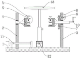
FIG. 1 is a schematic view of a front cross-sectional structure of the present invention;
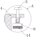
FIG. 2 is an enlarged schematic view of the structure at A in FIG. 1;
fig. 3 is an enlarged schematic view of B in fig. 1.
In the figure: the heat radiation device comprises a base 1, a first support frame 2, a second support frame 3, a fixed block 4, a fixed bolt 5, a clamping block 6, a limiting plate 7, a limiting rod 8, a sliding block 9, a rotating rod 10, a screw rod 11, a heat radiation fan 12, a magnifying lens 13 and a pressing block 14.
Detailed Description
The technical solutions in the embodiments of the present invention will be described clearly and completely with reference to the accompanying drawings in the embodiments of the present invention, and it is obvious that the described embodiments are only some embodiments of the present invention, not all embodiments. Based on the embodiments in the present invention, all other embodiments obtained by a person skilled in the art without creative work belong to the protection scope of the present invention.
Referring to fig. 1-3, the present invention provides a technical solution: the utility model provides a circuit board clamp, the on-line screen storage device comprises a base 1, base 1's upper surface difference fixedly connected with radiator fan 12 and telescopic link, the telescopic end fixedly connected with magnifying glass 13 of telescopic link, radiator fan 12 passes through the wire and connects outside power supply, base 1's upper surface is provided with first support frame 2 and second support frame 3 respectively, the mounting groove has been seted up to the side of second support frame 3, the inner wall of mounting groove is pegged graft and is had gag lever post 8, gag lever post 8's fixed surface is connected with sliding block 9, sliding block 9's right side fixedly connected with limit spring, limit spring cup joints the surface at gag lever post 8.
The slide rail has been seted up to base 1's upper surface, first support frame 2 and slide rail sliding connection, threaded hole has been seted up to the side of first support frame 2, the inner wall threaded connection of screw hole has lead screw 11, the right-hand member of lead screw 11 is rotated through the bearing and is connected with the fixed plate, the left end fixedly connected with crank of lead screw 11, through setting up slide rail and 2 sliding connection of first support frame, rethread sets up lead screw 11 and crank, can rotate the crank and drive first support frame 2 and remove, and then can adjust the distance between first support frame 2 and the second support frame 3, can carry out the centre gripping to not unidimensional circuit board and fix, through setting up radiator fan 12, can dispel the heat to the circuit board in welding process, the practicality of this circuit board anchor clamps has been strengthened.
Round holes have been seted up respectively to the side of first support frame 2 and second support frame 3, the inner wall of two round holes rotates through the bearing respectively and is connected with head rod and second connecting rod, the equal fixedly connected with fixed block 4 of looks remote site of head rod and second connecting rod, the opposite face of two fixed blocks 4 is all seted up flutedly, the interior roof of recess sets up threaded hole, the inner wall threaded connection of screw hole has fixing bolt 5, expanding spring has been cup jointed on fixing bolt 5's surface, expanding spring's bottom fixedly connected with grip block 6, fixing bolt 5's bottom and grip block 6's upper surface overlap joint.
The equal fixedly connected with briquetting 14 of lower surface of grip block 6 and the interior diapire of recess, the material of briquetting 14 is soft rubber, has the briquetting 14 of soft rubber material through the surface that sets up grip block 6 and 4 recesses of fixed block, can play certain cushioning effect, prevents that anchor clamps from producing the vibration and producing the damage to the circuit board in welding process.
Two limiting plates 7 of fixed surface of second connecting rod, the through-hole has all been seted up to the side of two limiting plates 7, the position and the mounting groove of through-hole are corresponding, the right-hand member fixedly connected with bull stick 10 of the right-hand member of second connecting rod, through setting up first support frame 2, second support frame 3, the head rod, the second connecting rod, fixed block 4, grip block 6, fixing bolt 5 and bull stick 10, can carry out the centre gripping to the circuit board fixed, and can rotate, weld with the convenience to the tow sides of circuit board.
The working principle is as follows: when the circuit board clamp is used, firstly, according to the size of a circuit board, a crank is rotated, the crank drives a screw rod 11 to rotate, the screw rod 11 drives a first support frame 2 to move on a slide rail, so that the distance between two fixing blocks 4 is adjusted, then, the circuit board is placed in a groove of the fixing blocks 4, a fixing bolt 5 is rotated to move downwards, the bottom end of the fixing bolt 5 is abutted against a clamping block 6, the clamping block 6 drives a pressing block 14 to contact the circuit board, then, the fixing bolt 5 is screwed down to clamp and fix the circuit board, then, welding operation can be carried out on one surface of the circuit board, when the reverse side of the circuit board needs to be welded, a limiting rod 8 is pulled to pull the limiting rod 8 out of a through hole of the limiting rod 7, then, a rotating rod 10 is rotated to rotate the limiting rod 7 below a second connecting rod to the position of the limiting rod 8, the limiting rod 8 is loosened, the limiting rod 8 is inserted into the through hole by utilizing the resilience force of a telescopic spring, the circuit board can be prevented from rotating.
Although embodiments of the present invention have been shown and described, it will be appreciated by those skilled in the art that changes, modifications, substitutions and alterations can be made in these embodiments without departing from the principles and spirit of the invention, the scope of which is defined in the appended claims and their equivalents.
Claims (6)
1. The utility model provides a circuit board anchor clamps, includes base (1), its characterized in that: the upper surface of base (1) is provided with first support frame (2) and second support frame (3) respectively, the round hole has been seted up respectively to the side of first support frame (2) and second support frame (3), two the inner wall of round hole rotates through the bearing respectively and is connected with head rod and second connecting rod, the equal fixedly connected with fixed block (4) of looks remote site of head rod and second connecting rod, two the opposite face of fixed block (4) is all seted up flutedly, the interior roof of recess has seted up threaded hole, the inner wall threaded connection of screw hole has fixing bolt (5), expanding spring has been cup jointed on the surface of fixing bolt (5), expanding spring's bottom fixedly connected with grip block (6), the fixed surface of second connecting rod is connected with two limiting plates (7).
2. A circuit board holder according to claim 1, wherein: the mounting groove has been seted up to the side of second support frame (3), the inner wall of mounting groove is pegged graft and is had gag lever post (8), the fixed surface of gag lever post (8) is connected with sliding block (9), the right side fixedly connected with spacing spring of sliding block (9), spacing spring cup joints on the surface of gag lever post (8).
3. A circuit board holder according to claim 1, wherein: the side of two limiting plate (7) has all seted up the through-hole, the position and the mounting groove of through-hole are corresponding, the right-hand member fixedly connected with bull stick (10) of second connecting rod.
4. A circuit board holder according to claim 1, wherein: the upper surface of base (1) has seted up the slide rail, first support frame (2) and slide rail sliding connection, the side of first support frame (2) has seted up threaded hole, the inner wall threaded connection of threaded hole has lead screw (11), the right-hand member of lead screw (11) is rotated through the bearing and is connected with the fixed plate, the left end fixedly connected with crank of lead screw (11).
5. A circuit board holder according to claim 1, wherein: the upper surface of base (1) is fixedly connected with radiator fan (12) and telescopic link respectively, the flexible end fixedly connected with magnifying glass (13) of telescopic link.
6. A circuit board holder according to claim 1, wherein: the lower surface of the clamping block (6) and the inner bottom wall of the groove are fixedly connected with pressing blocks (14), and the pressing blocks (14) are made of soft rubber.
Priority Applications (1)
| Application Number | Priority Date | Filing Date | Title |
|---|---|---|---|
| CN202022712148.1U CN213880450U (en) | 2020-11-22 | 2020-11-22 | Circuit board clamp |
Applications Claiming Priority (1)
| Application Number | Priority Date | Filing Date | Title |
|---|---|---|---|
| CN202022712148.1U CN213880450U (en) | 2020-11-22 | 2020-11-22 | Circuit board clamp |
Publications (1)
| Publication Number | Publication Date |
|---|---|
| CN213880450U true CN213880450U (en) | 2021-08-03 |
Family
ID=77035732
Family Applications (1)
| Application Number | Title | Priority Date | Filing Date |
|---|---|---|---|
| CN202022712148.1U Active CN213880450U (en) | 2020-11-22 | 2020-11-22 | Circuit board clamp |
Country Status (1)
| Country | Link |
|---|---|
| CN (1) | CN213880450U (en) |
Cited By (1)
| Publication number | Priority date | Publication date | Assignee | Title |
|---|---|---|---|---|
| CN115942715A (en) * | 2022-12-31 | 2023-04-07 | 广东电力通信科技有限公司 | A method and device for installing liftable modules of CPE equipment |
-
2020
- 2020-11-22 CN CN202022712148.1U patent/CN213880450U/en active Active
Cited By (1)
| Publication number | Priority date | Publication date | Assignee | Title |
|---|---|---|---|---|
| CN115942715A (en) * | 2022-12-31 | 2023-04-07 | 广东电力通信科技有限公司 | A method and device for installing liftable modules of CPE equipment |
Similar Documents
| Publication | Publication Date | Title |
|---|---|---|
| CN212144565U (en) | Full-automatic three-dimensional drilling device | |
| CN219841272U (en) | A computer device for industrial image detection | |
| CN108406188B (en) | A kind of sewing machine base bracket special welding machine | |
| CN210548859U (en) | A mechanical automatic welding device | |
| CN213196332U (en) | Welding clamping device with adjustable angle | |
| CN211539897U (en) | A quick spot welding device for cell-phone antenna copper sheet | |
| CN211860712U (en) | A universal optical device FPC fast welding fixture | |
| CN220921605U (en) | Cabinet plate processing equipment | |
| CN108788371B (en) | Anti-drop's electronic components welding uses support frame | |
| CN209936075U (en) | Chip assembly tool convenient to operation | |
| CN211331951U (en) | Steel plate welding device | |
| CN219379581U (en) | Welding jig for reducing welding internal resistance | |
| CN223802415U (en) | Fixing device for sapphire glass processing | |
| CN221019826U (en) | Four-axis processing jig for barreled handles | |
| CN211052984U (en) | Welding jig convenient to adjust fixed angle | |
| CN213500955U (en) | A positioner is used in engineering plastics welding for nonstandard automation equipment | |
| CN221817807U (en) | Welding equipment of sealing assembly | |
| CN219387196U (en) | A construction formwork fixture | |
| CN221363417U (en) | Welding set is used in processing of electricity-saving lamp fin | |
| CN223502787U (en) | A new energy photovoltaic support bracket | |
| CN218728448U (en) | Polaroid stripping jig | |
| CN217191913U (en) | A workpiece positioning device for punching machine | |
| CN221538733U (en) | Copper pipe welding equipment for air conditioner maintenance | |
| CN222735043U (en) | A lithium battery tab positioning mechanism | |
| CN222779015U (en) | Photovoltaic mounting panel welding equipment |
Legal Events
| Date | Code | Title | Description |
|---|---|---|---|
| GR01 | Patent grant | ||
| GR01 | Patent grant |