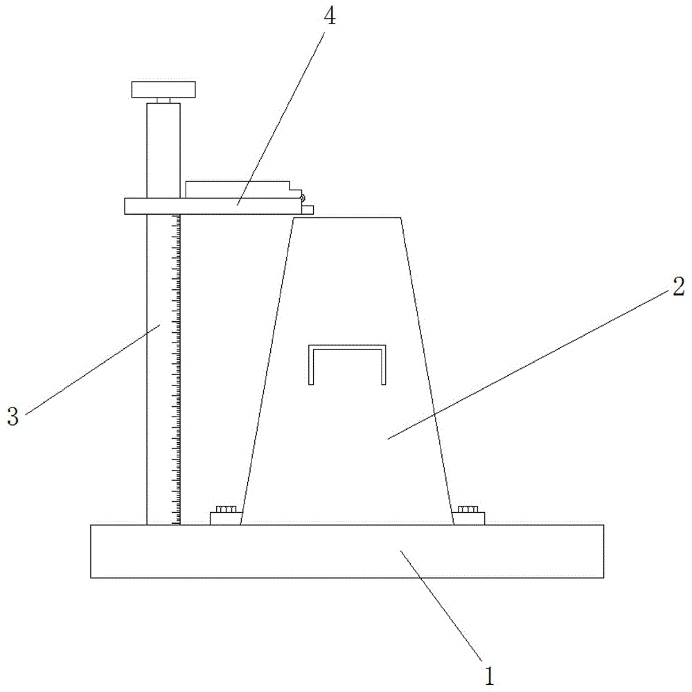
Floor type measuring scale for detecting slump of cement concrete
Technical Field
The utility model relates to a concrete slump tests technical field, especially relates to a console mode measurement scale for cement concrete slump detects.
Background
Slump is an important property of cement concrete, and directly influences the plasticizing performance and the pumpability of the cement concrete. The existing slump measuring instrument is mainly a slump measuring cylinder, and the working principle of the slump measuring instrument is that cement concrete mixture is filled into a standard conical slump cylinder according to a specified method, and after the cylinder is filled and scraped, the cylinder is lifted upwards vertically and moved aside. The cement concrete mixture will slump due to its own weight. Then the height of the downward slump is measured, and the size of the height is the slump.
At present most occasions are measured through measuring the scale to concrete slump's measurement, however present measurement scale still has some weak points in the use, for example after packing into the inside cement of barrel, need take out the barrel, the horizontal marker post on the dipperstick influences operating personnel easily and gets and put the barrel this moment, current horizontal marker post is whole shaping generally simultaneously, long time easily in the use because the dead weight leads to horizontal marker post to take place the bending, thereby influence measured data's accuracy, consequently, provide a console mode measurement scale that is used for cement concrete slump to detect and solve foretell problem.
Disclosure of Invention
The utility model aims to provide a: in order to solve the problems, a floor-type measuring scale for detecting the slump of the cement concrete is provided.
In order to achieve the above purpose, the utility model adopts the following technical scheme:
the utility model provides a console mode measuring scale for cement concrete slump detects, includes the base, sets up the barrel at base upper end intermediate position through fastening bolt, still includes the fixed vertical measuring ruler subassembly that sets up and be located the barrel left on the base, the cover is equipped with on the vertical measuring ruler subassembly and is used for cooperating it to carry out the horizontal marker post subassembly of measuring.
As a further description of the above technical solution:
the horizontal marker post component comprises a first horizontal marker post section, one end, away from the vertical measuring scale component, of the first horizontal marker post section is provided with a second horizontal marker post section, two T-shaped clamping blocks are arranged inside the first horizontal marker post section, the T-shaped clamping blocks are connected with the inner wall of the first horizontal marker post section in a sliding mode, and a reset spring is arranged between the T-shaped clamping blocks and the inner wall of the first horizontal marker post section.
As a further description of the above technical solution:
the first horizontal marker post section is hinged to the second horizontal marker post section through a pin shaft, and a supporting plate is fixedly arranged at one end, close to the second horizontal marker post section, of the first horizontal marker post section.
As a further description of the above technical solution:
the vertical measuring scale subassembly includes that the fixed vertical measuring scale main part of establishing in the base upper end, the inside rotation in vertical measuring scale main part top is equipped with the dwang, the dwang upper end runs through vertical measuring scale main part inner wall and extends to its outside, the dwang upper end is equipped with the hood, the dwang is located the inside fixed surface in position of vertical measuring scale main part and is equipped with two arc lugs.
As a further description of the above technical solution:
the top cap is connected with the upper end of the rotating rod through threads.
As a further description of the above technical solution:
the annular groove is formed in the surface of the vertical measuring scale body and at the same height as the arc-shaped convex block, two extrusion blocks are symmetrically arranged inside the annular groove, and the extrusion blocks are arranged on the side wall of the vertical measuring scale body in a sliding mode.
As a further description of the above technical solution:
and a torsion spring is arranged between the rotating rod and the inner wall of the vertical measuring scale main body.
To sum up, owing to adopted above-mentioned technical scheme, the beneficial effects of the utility model are that:
in the utility model, the vertical measuring scale component can be used for screwing off the top cap and then taking out the horizontal marker post component under the condition of nonuse, thereby preventing the device from being damaged by collision; the horizontal marker post assembly can be folded and stored when not in use, so that the horizontal marker post assembly is prevented from being bent due to the influence of gravity for a long time and the measuring precision is prevented from being influenced; through adjusting the arc lug, can realize that the position of horizontal sighting rod subassembly in the vertical measuring chi main part is adjustable, conveniently measure the cement slump.
Drawings
Fig. 1 shows a schematic view of the overall appearance structure of a floor type measuring scale for detecting the slump of cement concrete according to the present invention;
fig. 2 shows an overall cross-sectional view of a floor-type measuring scale for detecting slump of cement concrete according to the present invention;
fig. 3 shows a schematic view of a floor type measuring scale for detecting slump of cement concrete according to the present invention;
fig. 4 shows a schematic structural diagram of a part a of a floor-type measuring scale for detecting slump of cement concrete according to the present invention;
fig. 5 shows according to the utility model provides a floor type measuring scale vertical measuring ruler subassembly inside overlook schematic structure for cement concrete slump detects.
Illustration of the drawings: 1. a base; 2. a barrel; 3. a vertical measurement scale assembly; 4. a horizontal pole assembly; 301. a vertical measuring scale main body; 302. rotating the rod; 303. an arc-shaped bump; 304. a top cap; 305. extruding the block; 401. a first horizontal flagpole segment; 402. a second horizontal flagpole section; 403. a T-shaped fixture block; 404. a return spring.
Detailed Description
The technical solutions in the embodiments of the present invention will be described clearly and completely with reference to the accompanying drawings in the embodiments of the present invention, and it is obvious that the described embodiments are only some embodiments of the present invention, not all embodiments. Based on the embodiments of the present invention, all other embodiments obtained by a person of ordinary skill in the art without creative efforts belong to the protection scope of the present invention.
Referring to fig. 1-5, the present invention provides a technical solution: the utility model provides a console mode measuring scale for cement concrete slump detects, includes base 1, sets up barrel 2 at 1 upper end intermediate position of base through fastening bolt, still includes fixed the setting and is located the left vertical measurement chi subassembly 3 of barrel 2 in 1 upper end of base, and the cover is equipped with on the vertical measurement chi subassembly 3 to be used for cooperating it to carry out measuring horizontal marker post subassembly 4.
Further, horizontal marker post subassembly 4 includes first horizontal marker post section 401, and the one end that vertical measurement chi subassembly 3 was kept away from to first horizontal marker post section 401 is equipped with second horizontal marker post section 402, and first horizontal marker post section 401 is inside to be equipped with two T type fixture blocks 403, T type fixture block 403 and first horizontal marker post section 401 inner wall sliding connection, and be equipped with reset spring 404 between T type fixture block 403 and the first horizontal marker post section 401 inner wall.
Further, first horizontal marker post section 401 is articulated through the round pin axle with second horizontal marker post section 402, and first horizontal marker post section 401 is close to the fixed layer board that is equipped with of one end of second horizontal marker post section 402 to in second horizontal marker post section 402 expansion back, guarantee that second horizontal marker post section 402 and first horizontal marker post section 401 are in same horizontal plane.
Further, vertical measuring rule subassembly 3 includes that the fixed vertical measuring rule main part 301 of establishing in base 1 upper end, and the inside rotation in vertical measuring rule main part 301 top is equipped with dwang 302, and dwang 302 upper end runs through vertical measuring rule main part 301 inner wall and extends to its outside, and dwang 302 upper end is equipped with hood 304, and the fixed surface of the position that dwang 302 is located vertical measuring rule main part 301 inside is equipped with two arc lugs 303.
Further, the top cap 304 is connected with the upper end of the rotating rod 302 through threads, so that the top cap is convenient to disassemble.
Further, an annular groove is formed in the surface of the vertical measuring scale main body 301 and at the same height position of the arc-shaped convex block 303, two extrusion blocks 305 are symmetrically arranged inside the annular groove, and the extrusion blocks 305 are arranged on the side wall of the vertical measuring scale main body 301 in a sliding mode.
Further, a torsion spring is arranged between the rotating rod 302 and the inner wall of the vertical measuring scale main body 301, so that the rotating rod 302 can be reset conveniently.
The working principle is as follows: when the device is used, the top cap 304 is detached from the rotating rod 302, the horizontal marker post assembly 4 is further sleeved on the vertical measuring scale main body 301, the top cap 304 is screwed down again, the horizontal marker post assembly 4 is further clamped into the annular groove on the surface of the vertical measuring scale main body 301, the horizontal marker post assembly 4 is further rotated to one side far away from the barrel 2, the barrel 2 is further fixedly arranged on the base 1 through the fastening bolt, cement to be detected is further injected into the barrel 2, after the cement is filled, the second horizontal marker post section 402 on the first horizontal marker post section 401 is unfolded, the first horizontal marker post section 401 is rotated at the same time, the cement at the upper end of the barrel 2 is scraped by the second horizontal marker post section 402, the barrel 2 is further vertically taken out, the top cap 304 is further rotated, the top cap 304 drives the rotating rod 302 to rotate, the rotating rod 302 further drives the arc-shaped bump 303 to rotate, the arc-shaped convex block 303 further extrudes the T-shaped fixture block 403 through the extrusion block 305, so that the T-shaped fixture block 403 is withdrawn from the annular groove, and further moves on the surface of the vertical measuring scale main body 301 through controlling the first horizontal marker post segment 401, so as to measure the actual height of cement at the moment, and the slump of the cement can be measured by observing the scale on the surface of the vertical measuring scale main body 301 at the moment.
The above, only be the concrete implementation of the preferred embodiment of the present invention, but the protection scope of the present invention is not limited thereto, and any person skilled in the art is in the technical scope of the present invention, according to the technical solution of the present invention and the utility model, the concept of which is equivalent to replace or change, should be covered within the protection scope of the present invention.