Waste heat utilization device of freezing type dryer
Technical Field
The utility model relates to a desiccator waste heat utilization technical field, more specifically relates to freezing formula desiccator waste heat utilization equipment.
Background
The freeze dryer is an air dryer that freezes moisture in compressed air to below a dew point by using a physical principle to be precipitated from the air. Limited by the freezing point temperature of water, theoretically, the dew point temperature of the freeze dryer can be close to 0 ℃, in practical situations, the good dew point temperature of the freeze dryer is about 5 ℃, the freeze dryer can generate drying air with extremely low temperature during normal work, the low-temperature drying air is directly discharged into the air, so that people are very easy to feel uncomfortable and even seriously hurt the people, meanwhile, the freeze dryer can generate a large amount of waste heat, and the waste heat is not utilized, so that the resource waste is caused.
In chinese utility model patent application no: CN201620280812.0 discloses a dryer waste heat recycling system, which includes a waste gas discharge chimney, a water storage tank, a water drain pipe, a spray device, a spiral-flow plate, a wire mesh demister, a water replenishing device and a hot water utilization device, wherein the waste gas discharge chimney is vertically arranged, and the bottom of the waste gas discharge chimney and the horizontal plane are arranged at a first preset angle α; the bottom end of the waste gas discharge chimney is communicated with the top end of the water storage tank through the water drain pipe; the spraying device, the rotational flow plate and the wire mesh demister are arranged inside the waste gas emission chimney. This desiccator waste heat recovery utilizes system can't carry out make full use of to the waste heat that the air drying in-process produced for the utilization efficiency of waste heat is lower, has caused the wasting of resources.
Therefore, it is necessary to provide a waste heat utilization device of a freeze dryer to solve the above problems.
SUMMERY OF THE UTILITY MODEL
Technical problem to be solved
The utility model aims to provide a: in order to solve desiccator waste heat recovery and utilization system, can't carry out make full use of to the waste heat that the air drying in-process produced for the utilization efficiency of waste heat is lower, has caused the problem of wasting of resources, the utility model provides a freezing type desiccator waste heat utilization device.
(II) technical scheme
The utility model discloses a realize above-mentioned purpose and specifically adopt following technical scheme:
the waste heat utilization device of the freezing type dryer comprises a dryer body, wherein a drying bin is arranged on one side inside the dryer body, a freezing type drying device is fixedly connected to the middle of the bottom end of the drying bin, a condensing bin is arranged inside the freezing type drying device, a heat exchange device is fixedly connected to the top of the drying bin, a compressor is fixedly connected to the top of the heat exchange device, an air inlet pipe is fixedly connected to the middle of one side of the inner wall of the drying bin, an air exhaust groove is formed in the middle of the other side of the inner wall of the drying bin, a first heating pipe is spirally arranged inside the air exhaust groove, two ends of the first heating pipe extend out of the air exhaust groove and are communicated with the heat exchange device, a water storage bin is formed in the top of the air exhaust groove, filter screens are fixedly connected to one sides, close to the air inlet pipe, of the drying bin and the condensing bin, and a brush plate is movably connected between the two filter screens, the top and the bottom of one side of the inside of the drying bin close to the air inlet pipe are both rotatably connected with a screw rod.
Further, the bottom one side fixedly connected with water pump in dry storehouse, the water inlet and the delivery port of water pump have the connecting pipe with the bottom in condensation storehouse and the top intercommunication in water storage storehouse respectively, the inner wall top fixedly connected with inlet tube in water storage storehouse, the inner wall bottom fixedly connected with drain pipe in water storage storehouse.
Further, the bottom fixedly connected with second heating pipe of water storage storehouse, the second heating pipe has a plurality ofly, and is a plurality of second heating pipe evenly distributed, the both ends of second heating pipe all are linked together with heat exchange device.
Further, the bottom fixedly connected with condenser pipe of heat exchange device, the condenser pipe has a plurality ofly, and is a plurality of the condenser pipe is even respectively, the bottom of condenser pipe all stretches into in the condensation storehouse.
Furthermore, the condensation bin is provided with a plurality of air holes on one side close to the inner wall of the exhaust groove, and the air holes are uniformly distributed in a rectangular shape.
Further, the bottom in dry storehouse is equipped with the dust containing box, inner wall one side of dust containing box is equipped with the chamber door, the intercommunication has the ash discharge groove between top one side of dust containing box and the dry storehouse, the ash discharge groove is located between the bottom of two filter screens.
Further, the inner wall rear side that the drying chamber is close to the intake pipe is opened and is equipped with the driving groove, the one end of two screw rods all stretches into driving groove and fixedly connected with second driven pulleys, the other end of one of them screw rod stretches out the first driven pulleys of desiccator body and fixedly connected with.
Furthermore, a servo motor is fixedly connected to the top of the outer wall of one side of the dryer body, which is close to the first driven pulley, a driving pulley is fixedly connected to an output shaft of the servo motor, and V-shaped belts are respectively connected between the driving pulley and the first driven pulley and between the two second driven pulleys.
Further, the top of the brush board is provided with threaded holes close to the bottom, and the brush board is respectively in threaded connection with the two screws through the two threaded holes.
(III) advantageous effects
The utility model has the advantages as follows:
1. the utility model discloses, through setting up air discharge duct, first heating pipe, compressor, heat exchange device and freeze-drying device, waste heat recovery that can produce when freezing dryer drying air and utilize the waste heat to carry out the intensification processing to the air after the drying, avoided low temperature drying air directly to discharge very easily to make the people produce uncomfortable condition in the air and taken place, also avoided the energy extravagant simultaneously.
2. The utility model discloses, through setting up water pump, reservoir bin, second heating pipe, heat exchange device and connecting pipe, the comdenstion water that produces when can be to the dry air of freezing type desiccator is retrieved to the waste heat that utilizes the desiccator device to produce heats, has improved the practical of desiccator, has practiced thrift the water resource simultaneously and can accord with national sustainable development strategy.
3. The utility model discloses, through setting up filter screen, brush board, dust discharging groove, dust containing box, screw hole and screw rod, can filter the air that enters into the desiccator inside, avoid the dust in the air to enter into the inside condensation effect that influences the condenser pipe of desiccator to the condition that leads to the utilization efficiency of desiccator waste heat to reduce takes place.
Drawings
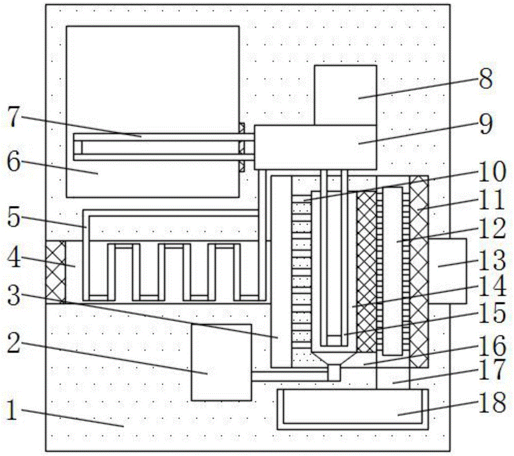
Fig. 1 is a schematic perspective view of the structure of the present invention;
FIG. 2 is a schematic sectional view of the structure of the present invention;
FIG. 3 is a schematic side view of the structure of the present invention;
fig. 4 is a schematic top sectional view of the structure of the present invention.
Reference numerals: 1. a dryer body; 2. a water pump; 3. a drying bin; 4. an exhaust groove; 5. a first heating pipe; 6. a water storage bin; 7. a second heating pipe; 8. a compressor; 9. a heat exchange device; 10. a vent hole; 11. filtering with a screen; 12. brushing the board; 13. an air inlet pipe; 14. a condensation bin; 15. a condenser tube; 16. a freeze-drying device; 17. an ash discharge groove; 18. a dust storage box; 19. a threaded hole; 20. a transmission groove; 21. A second driven pulley; 22. a servo motor; 23. a driving pulley; 24. a V-belt; 25. a first driven pulley; 26. a screw; 27. a box door; 28. a connecting pipe; 29. a drain pipe; 30. and (4) a water inlet pipe.
Detailed Description
The technical solutions in the embodiments of the present invention will be described clearly and completely with reference to the accompanying drawings in the embodiments of the present invention, and it is obvious that the described embodiments are only some embodiments of the present invention, not all embodiments. Based on the embodiments in the present invention, all other embodiments obtained by a person skilled in the art without creative work belong to the protection scope of the present invention.
Example 1
Referring to fig. 1-4, the waste heat utilization device of the freezing dryer comprises a dryer body 1, a drying chamber 3 is formed in one side of the interior of the dryer body 1, a freezing drying device 16 is fixedly connected to the middle portion of the bottom end of the drying chamber 3, a condensing chamber 14 is formed in the freezing drying device 16, a heat exchange device 9 is fixedly connected to the top of the drying chamber 3, a compressor 8 is fixedly connected to the top of the heat exchange device 9, an air inlet pipe 13 is fixedly connected to the middle portion of one side of the inner wall of the drying chamber 3, an air discharge groove 4 is formed in the middle portion of the other side of the inner wall of the drying chamber 3, a first heating pipe 5 is spirally arranged in the air discharge groove 4, two ends of the first heating pipe 5 extend out of the air discharge groove 4 and are communicated with the heat exchange device 9, a water storage chamber 6 is formed in the top of the air discharge groove 4, and a filter screen 11 is fixedly connected to one side of the inner walls of the drying chamber 3 and the condensing chamber 14 close to the air inlet pipe 13, the brush plate 12 is movably connected between the two filter screens 11, and the top and the bottom of one side of the inside of the drying chamber 3 close to the air inlet pipe 13 are both rotatably connected with a screw 26.
In this embodiment, by providing the exhaust duct 4, the first heating pipe 5, the compressor 8, the heat exchanging device 9, and the freeze-drying device 16, waste heat generated when the freeze-drying machine dries air can be recovered and the waste heat can be utilized to heat up the dried air, so that the situation that the direct discharge of low-temperature dried air into air is easily uncomfortable is avoided, and energy waste is also avoided.
Example 2
Referring to fig. 2 and 4, the present embodiment is further optimized based on embodiment 1, specifically, a water pump 2 is fixedly connected to one side of the bottom of the drying bin 3, a water inlet and a water outlet of the water pump 2 are respectively communicated with the bottom of the condensing bin 14 and the top of the water storage bin 6 through a connecting pipe 28, a water inlet pipe 30 is fixedly connected to the top of the inner wall of the water storage bin 6, and a water outlet pipe 29 is fixedly connected to the bottom of the inner wall of the water storage bin 6.
Specifically, the bottom of the water storage bin 6 is fixedly connected with a plurality of second heating pipes 7, the plurality of second heating pipes 7 are uniformly distributed, and two ends of each second heating pipe 7 are communicated with a heat exchange device 9.
Specifically, heat exchange device 9's bottom fixedly connected with condenser pipe 15, condenser pipe 15 have a plurality ofly, and a plurality of condenser pipes 15 are even respectively, and condenser pipe 15's bottom all stretches into in condensation bin 14.
Specifically, the condensation bin 14 is provided with a plurality of vent holes 10 on one side close to the inner wall of the exhaust duct 4, and the vent holes 10 are uniformly distributed in a rectangular shape.
In this embodiment, through setting up water pump 2, reservoir 6, second heating pipe 7, heat exchange device 9 and connecting pipe 28, the comdenstion water that produces when can being to the dry air of freeze dryer is retrieved to the waste heat that utilizes the desiccator device to produce heats, has improved the practicality of desiccator, has practiced thrift the water resource simultaneously and can accord with national sustainable development strategy.
Example 3
Referring to fig. 2-4, the present embodiment is optimized based on the embodiment 1 or 2, specifically, a dust storage box 18 is disposed at the bottom of the drying chamber 3, a door 27 is disposed at one side of the inner wall of the dust storage box 18, an ash discharge groove 17 is communicated between one side of the top of the dust storage box 18 and the drying chamber 3, and the ash discharge groove 17 is located between the bottoms of the two filter screens 11.
Specifically, the rear side of the inner wall of the drying bin 3 close to the air inlet pipe 13 is provided with a transmission groove 20, one ends of two screws 26 all extend into the transmission groove 20 and are fixedly connected with second driven belt pulleys 21, and the other end of one screw 26 extends out of the drying machine body 1 and is fixedly connected with a first driven belt pulley 25.
Specifically, the dryer body 1 is close to one side outer wall top fixedly connected with servo motor 22 of first driven pulley 25, fixedly connected with driving pulley 23 on servo motor 22's the output shaft, and it is connected with V-belt 24 all to take between driving pulley 23 and the first driven pulley 25 and between two second driven pulleys 21.
Specifically, the top of the brush plate 12 is provided with a threaded hole 19 near the bottom, and the brush plate 12 is respectively in threaded connection with two screws 26 through the two threaded holes 19.
In this embodiment, through setting up filter screen 11, brush board 12, row's ash groove 17, dust containing box 18, screw hole 19 and screw rod 26, can filter the inside air that enters into the desiccator, avoid the dust in the air to enter into the inside condensation effect that influences condenser pipe 15 of desiccator to the condition that leads to the utilization efficiency of desiccator waste heat to reduce takes place.
In summary, the following steps: the utility model discloses, waste heat recovery that can produce when drying the air with the freezing dryer and utilize the waste heat to carry out the intensification processing to the air after the drying, it very easily makes the people produce uncomfortable condition to take place to have avoided low temperature drying air to directly discharge in the air, the comdenstion water that produces when can be to freezing dryer drying air simultaneously is retrieved, and the waste heat that utilizes the desiccator to produce heats, the practicality of desiccator is improved, the waste heat utilization efficiency of desiccator is improved, the water resource has been practiced thrift simultaneously and the sustainable development strategy that can accord with the country.
The above description is only a preferred embodiment of the present invention, and not intended to limit the present invention, and the scope of the present invention is defined by the appended claims, and all structural changes that can be made by using the contents of the description and the drawings of the present invention are intended to be covered by the scope of the present invention.