Novel transmission device for three-side turnover box body
Technical Field
The utility model relates to a trilateral technical field that turns over especially relates to a novel trilateral box body transmission that turns over device.
Background
The three-face turning box body transmission device is generally used for three-face turning advertising boards, the three-face turning advertising board is an advertising board for displaying three advertising pictures on the same advertising position in a changing way, mainly comprises a picture displaying part and a transmission mechanism part, the picture displaying part comprises a plurality of regular triangular prisms, the transmission mechanism part plays a role in driving and transmitting, drives the triangular prisms to rotate by 120 degrees every time, and realizes the turning action of the triangular prisms,
the existing three-face turning box body transmission device is characterized in that each group is driven respectively, adjacent groups are not connected in power, once a certain group fails, the problem of dislocation of pictures can occur, the transmission system has more components and a complex structure, when one gear part is damaged and needs to be replaced, a driving shaft needs to be dismounted, all the gear parts on a transmission shaft are dismounted, the gear parts are mounted again after being replaced, and the maintenance and the dismounting are very troublesome.
SUMMERY OF THE UTILITY MODEL
The utility model aims at solving the defects existing in the prior art and providing a novel three-side turning box body transmission device.
In order to achieve the above purpose, the utility model adopts the following technical scheme: a novel three-face turning box body transmission device comprises a box body, wherein a supporting frame is fixedly connected to the inner bottom wall of the box body, a motor is fixedly connected to one side of the side wall of the supporting frame, a driving end of the motor extends to the inner portion of the supporting frame, one end, away from the motor, of the driving shaft is rotatably connected with the inner side wall of the supporting frame, a plurality of first bevel gears are sleeved on the outer surface of the driving shaft, a plurality of three-face turning advertising boards which are orderly arranged are arranged above the box body, rotating rods are fixedly connected to the bottoms of the three-face turning advertising boards, the bottom ends of the rotating rods extend to the inner portion of the box body, second bevel gears are sleeved at the bottom ends of the rotating rods, the first bevel gears are meshed with the second bevel gears, a control box is fixedly embedded on the inner bottom wall of the box body, and the first bevel gears and the second bevel gears are divided into first half gears and second half gears, two mounting grooves are seted up to one side of first semi-gear that is close to second semi-gear, two the inside of mounting groove all is provided with the installation piece, one side of installation piece and the lateral wall fixed connection of second semi-gear, one side of mounting groove is seted up flutedly, the mounting groove is close to one side of recess and has seted up the fixed slot, the first spring of inner wall fixedly connected with of recess, the one end fixedly connected with fixed block of first spring, the one end that first spring was kept away from to the fixed block extends to the inside of fixed slot.
As a further description of the above technical solution:
a plurality of draw-in grooves have all been seted up to the inside of driving shaft and dwang, the equal fixedly connected with a plurality of fixture blocks of the inside wall of first semi-gear and second semi-gear, it is a plurality of the fixture block extends to the inside of a plurality of draw-in grooves respectively.
As a further description of the above technical solution:
the inside fixedly connected with fixed plate of fixed slot, the inside of fixed slot is provided with T type pole, the surface of T type pole has cup jointed the second spring, the lateral wall of fixed plate is passed to the one end of T type pole, the one end of second spring and the lateral wall fixed connection of fixed plate, and the other end of second spring and the lateral wall fixed connection of T type pole.
As a further description of the above technical solution:
one side fixedly connected with push rod of T type pole, the bar mouth has been seted up to the lateral wall of fixed slot, the one end of push rod passes the bar mouth and extends to the outside of first semi-gear.
As a further description of the above technical solution:
the control box is electrically connected with the motor.
As a further description of the above technical solution:
an access door is arranged on the side wall of the box body.
The utility model discloses following beneficial effect has:
1. this use is novel through the setting of first bevel gear, second bevel gear, motor, dwang, driving shaft, makes a plurality of trilateral billboards turn over and can carry out synchronous rotation through a motor drive is whole, avoids appearing the phenomenon of picture dislocation, and simple structure.
2. The utility model discloses a setting of first half gear, second half gear, first spring, fixed block, installation piece, mounting panel, second spring, push rod, T type pole makes the dismantlement and the installation of a plurality of first bevel gears and second bevel gear more convenient, can directly separately pull down it when transmission inside arbitrary bevel gear takes place to damage or wearing and tearing and change, makes its maintenance of being convenient for more.
Drawings
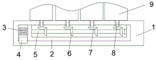
Fig. 1 is a main sectional view of a novel three-side turnover box transmission device provided by the utility model;
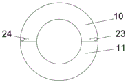
fig. 2 is a partial side sectional view of a novel three-side-turning box transmission device provided by the utility model;
fig. 3 is a partial side view of a novel three-side-turning box transmission device provided by the present invention;
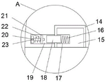
fig. 4 is an enlarged view of a novel three-side turning box transmission device a provided by the utility model.
Illustration of the drawings:
1. a box body; 2. a support frame; 3. a motor; 4. a control box; 5. a drive shaft; 6. a first bevel gear; 7. a second bevel gear; 8. rotating the rod; 9. a three-face turning advertisement board; 10. a first half gear; 11. a second half gear; 12. a card slot; 13. a clamping block; 14. mounting grooves; 15. mounting blocks; 16. a first spring; 17. a groove; 18. a fixed block; 19. fixing grooves; 20. a T-shaped rod; 21. a fixing plate; 22. a second spring; 23. a push rod; 24. a strip-shaped opening.
Detailed Description
The technical solutions in the embodiments of the present invention will be described clearly and completely with reference to the accompanying drawings in the embodiments of the present invention, and it is obvious that the described embodiments are only some embodiments of the present invention, not all embodiments. Based on the embodiments in the present invention, all other embodiments obtained by a person skilled in the art without creative work belong to the protection scope of the present invention.
In the description of the present invention, it should be noted that the terms "center", "upper", "lower", "left", "right", "vertical", "horizontal", "inner", "outer", and the like indicate orientations or positional relationships based on the orientations or positional relationships shown in the drawings, and are only for convenience of description and simplification of description, but do not indicate or imply that the device or element referred to must have a specific orientation, be constructed and operated in a specific orientation, and thus, should not be construed as limiting the present invention; the terms "first," "second," and "third" are used for descriptive purposes only and are not to be construed as indicating or implying relative importance, and furthermore, unless otherwise explicitly stated or limited, the terms "mounted," "connected," and "connected" are to be construed broadly and may be, for example, fixedly connected, detachably connected, or integrally connected; can be mechanically or electrically connected; they may be connected directly or indirectly through intervening media, or they may be interconnected between two elements. The specific meaning of the above terms in the present invention can be understood in specific cases to those skilled in the art.
Referring to fig. 1-4, the present invention provides an embodiment: a novel three-face turning box body transmission device comprises a box body 1, wherein a supporting frame 2 is fixedly connected to the inner bottom wall of the box body 1, a motor 3 is fixedly connected to one side of the side wall of the supporting frame 2, the driving end of the motor 3 extends to the inside of the supporting frame 2 and is fixedly connected with a driving shaft 5, one end, away from the motor 3, of the driving shaft 5 is rotatably connected with the inner side wall of the supporting frame 2, a plurality of first bevel gears 6 are sleeved on the outer surface of the driving shaft 5, a plurality of three-face turning advertising boards 9 which are orderly arranged are arranged above the box body 1, rotating rods 8 are fixedly connected to the bottoms of the three-face turning advertising boards 9, the bottom ends of the rotating rods 8 extend to the inside of the box body 1, second bevel gears 7 are sleeved at the bottom ends of the rotating rods 8, the first bevel gears 6 are meshed with the second bevel gears 7, a control box 4 is fixedly embedded in the inner bottom wall of the box body 1, the first bevel gears 6 and the second bevel gears 7 are divided into a first half gear 10 and a second half gear 11, two mounting grooves 14 have been seted up to one side that is close to second half-gear 11 of first half-gear 10, the inside of two mounting grooves 14 all is provided with installation piece 15, one side of installation piece 15 and the lateral wall fixed connection of second half-gear 11, recess 17 has been seted up to one side of mounting groove 14, mounting groove 14 has been close to one side of recess 17 and has been seted up fixed slot 19, the first spring 16 of inner wall fixedly connected with of recess 17, the one end fixedly connected with fixed block 18 of first spring 16, the one end that first spring 16 was kept away from to fixed block 18 extends to the inside of fixed slot 19.
A plurality of draw-in grooves 12 have all been seted up to the inside of driving shaft 5 and dwang 8, and a plurality of fixture blocks 13 of the equal fixedly connected with of inside wall of first semi-gear 10 and second semi-gear 11, a plurality of fixture blocks 13 extend to the inside of a plurality of draw-in grooves 12 respectively, avoid taking place relative rotation between first bevel gear 6 and second bevel gear 7 and driving shaft 5 and dwang 8.
The inside fixedly connected with fixed plate 21 of fixed slot 19, the inside of fixed slot 19 is provided with T type pole 20, and second spring 22 has been cup jointed to the surface of T type pole 20, and the lateral wall of fixed plate 21 is passed to the one end of T type pole 20, and the one end of second spring 22 and the lateral wall fixed connection of fixed plate 21, and the other end of second spring 22 and the lateral wall fixed connection of T type pole 20 are convenient for fix first half-gear 10 and second half-gear 11.
One side fixedly connected with push rod 23 of T type pole 20, bar mouth 24 has been seted up to the lateral wall of fixed slot 19, and the one end of push rod 23 is passed bar mouth 24 and is extended to the outside of first half-gear 10 to carry out quick dismantlement change to first half-gear 10 and second half-gear 11.
Control box 4 and motor 3 electric connection conveniently control motor 3 and rotate, make motor 3 rotatory degree at every turn be 120 degrees.
The access door has been seted up to the lateral wall of box body 1, makes things convenient for the inside maintenance of box body 1.
The working principle is as follows: when needs overturn, starter motor 3, motor 3 drives driving shaft 5 and rotates driving shaft 5 and drive a plurality of first bevel gear 6 and rotate, a plurality of first bevel gear 6 drive a plurality of second bevel gear 7 and rotate, a plurality of second bevel gear 7 drive a plurality of dwang 8 initiatives, a plurality of dwang 8 drive a plurality of trilateral advertisement boards 9 of turning over and rotate simultaneously to make trilateral advertisement board 9 of turning over rotate 120 degrees at every turn through control box 4 control motor 3, realize trilateral upset.
Finally, it should be noted that: although the present invention has been described in detail with reference to the foregoing embodiments, it will be apparent to those skilled in the art that modifications and variations can be made in the embodiments or in part of the technical features of the embodiments without departing from the spirit and the scope of the invention.