Firm structure of highway communication tower
Technical Field
The utility model relates to a communication tower technical field specifically is a firm structure of highway communication tower.
Background
Along with the continuous increase of the highway mileage in China, the ever-increasing urban traffic trip demand of people is met, the trip of people is more convenient, efficient, quick and comfortable, the rapid development of social economy is driven, various tower bodies and rod bodies of communication towers, water supply towers, power grid towers, light pole, monitoring poles … … are indispensable infrastructures in cities, the phenomena of 'single tower, single pole and single use' are common all the time, and therefore the city traffic trip demand monitoring system brings many problems: the single use causes resource waste and increases the construction cost; the tower stands in forest, and the dense lines easily cause visual pollution and operation cost.
The existing highway communication tower cannot be stably supported, firmness and stability are insufficient, wind blowing shaking can be caused, construction cost is high, decorative advertising boards and warning boards are inconvenient, rapid and safe to install, stability is low, environmental protection performance is low, and the requirement for the stable structure of the existing highway communication tower cannot be met easily.
SUMMERY OF THE UTILITY MODEL
Technical problem to be solved
An object of the utility model is to provide a firm structure of highway communication tower has solved the problem that proposes among the background art.
(II) technical scheme
In order to achieve the above purpose, the utility model discloses a following technical scheme realizes: a stable structure of a highway communication tower comprises a communication tower upright post, a tower tip signal enhancement device, a base and an installation rod, wherein the tower tip signal enhancement device is arranged at the top of the communication tower upright post, illuminating lamps are arranged on two sides of the upper end of the communication tower upright post, the installation rod is arranged at two ends of the communication tower upright post, an expansion support plate is connected to the outer end of the installation rod, a telescopic rod is connected to the inner side end of the installation rod, a lifting control device is electrically connected to the bottom of the telescopic rod, sliding rails are arranged on two sides of the communication tower upright post, a sliding block is slidably connected to the outer end of the sliding rails, a support rod is welded between the outer end of the sliding block and the bottom of the installation rod, solar electric plates are distributed at the top of the installation rod and the expansion support plate, a bottom plate is welded at the bottom of the communication tower upright post, first reinforcing ribs are welded and distributed between the outer end of the bottom plate and the communication tower upright post, a second reinforcing rib is welded between the first reinforcing rib and the bottom plate, and a base is arranged at the bottom of the bottom plate.
Preferably, the bottom of the communication tower upright post is welded with an insertion rod, and the insertion rod is positioned in the middle of the base.
Preferably, the two ends between the mounting rod and the expansion supporting plate are connected with sliding grooves, and the inner side end of the mounting rod is electrically connected with a telescopic motor.
Preferably, the upper end of the inner side of the communication tower upright post is welded with a limiting buffer device, and a rubber pad is bonded at the bottom of the limiting buffer device.
Preferably, through grooves are formed in two sides of the middle end of the communication tower upright post, and adapter rods are welded between two ends of the telescopic rod and the installation rod.
(III) advantageous effects
The utility model provides a firm structure of highway communication tower. The method has the following beneficial effects:
(1) this highway communication tower's firm structure, through bottom plate and the base that sets up bottom the communication tower stand, the base is made by reinforced concrete, improve fastness and stability, through the first strengthening rib of welded between bottom plate outer end and communication tower stand, and the second strengthening rib of welded between first strengthening rib and the bottom plate, make to support more stable, avoid the wind-blown to rock, sturdy and durable, the unstable problem of prior art has been avoided, and is with low costs, and facilitate promotion and application.
(2) This highway communication tower's firm structure, installation pole and the expansion fagging through setting up at the both ends of communication tower stand, be convenient for install the bill-board or the warning sign of different models, reasonable in design, through the inside lift control device through telescopic link electric connection at communication tower stand, be convenient for control goes up and down, make the installation simple safety more, through on the slide rail of installation pole bottom welded bracing piece in communication tower stand both sides, make to support and slide more convenient stably, through the solar energy electroplax at the installation pole with expand the top distribution of fagging, absorption power supply, energy-concerving and environment-protective.
Drawings
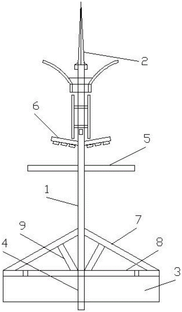
Fig. 1 is a schematic view of the overall structure of a stable structure of a highway communication tower according to the present invention;
fig. 2 is a schematic view of the installation structure of the billboard of the stable structure of the highway communication tower of the present invention;
fig. 3 is the utility model relates to a firm solar energy electroplax structural schematic of structure of highway communication tower.
In the figure: the device comprises a communication tower upright post 1, a tower tip signal enhancement device 2, a base 3, an insertion rod 4, an installation rod 5, a lighting lamp 6, a first reinforcing rib 7, a bottom plate 8, a second reinforcing rib 9, a lifting control device 10, a telescopic rod 11, a support expansion plate 12, a support rod 13, a slide rail 14, a slide block 15, a limiting buffer device 16, a solar panel 17 and a switching rod 18.
Detailed Description
The technical solutions in the embodiments of the present invention will be described clearly and completely with reference to the accompanying drawings in the embodiments of the present invention, and it is obvious that the described embodiments are only some embodiments of the present invention, not all embodiments. Based on the embodiments in the present invention, all other embodiments obtained by a person skilled in the art without creative work belong to the protection scope of the present invention.
Referring to fig. 1-3, an embodiment of the present invention provides a technical solution: a stable structure of a highway communication tower comprises a communication tower upright post 1, a tower tip signal enhancement device 2, a base 3 and an installation rod 5, wherein the tower tip signal enhancement device 2 is arranged at the top of the communication tower upright post 1, illuminating lamps 6 are arranged on two sides of the upper end of the communication tower upright post 1, the installation rod 5 is arranged at two ends of the communication tower upright post 1, the outer end of the installation rod 5 is connected with an expansion supporting plate 12, the inner side end of the installation rod 5 is connected with an expansion rod 11, the bottom of the expansion rod 11 is electrically connected with a lifting control device 10, sliding rails 14 are arranged on two sides of the communication tower upright post 1, a sliding block 15 is slidably connected at the outer end of each sliding rail 14, a support rod 13 is welded between the outer end of the sliding block 15 and the bottom of the installation rod 5, solar electric plates 17 are distributed on the top of the installation rod 5 and the expansion supporting plate 12, a bottom plate 8 is welded at the bottom of the communication tower upright post 1, the outer end of the bottom plate 8 and the communication tower upright post 1 are welded and distributed with a first reinforcing rib 7, a second reinforcing rib 9 is welded between the first reinforcing rib 7 and the bottom plate 8, and the bottom of the bottom plate 8 is provided with a base 3.
The bottom welding of communication tower stand 1 has grafting pole 4, grafting pole 4 is located the centre of base 3, and the direct grafting of being convenient for is underground, the installation of being convenient for.
The both ends between installation pole 5 and the expansion fagging 12 are connected with the spout, the medial extremity electric connection of installation pole 5 has flexible motor, and the automated control of being convenient for is flexible.
The upper end of the inner side of the communication tower upright post 1 is welded with a limiting buffer device 16, and a rubber pad is bonded at the bottom of the limiting buffer device 16, so that the damping is buffered, and the limiting is safe.
The both sides of the middle end of communication tower stand 1 all are equipped with logical groove, the welding has the switching pole 18 between the both ends of telescopic link 11 and the installation pole 5, is convenient for support and drives the lift.
The working principle is as follows: the communication tower upright post 1 is directly inserted and connected underground through an inserting rod 4 at the bottom, the communication tower upright post is firmly and stably arranged according to a bottom plate 8 and a base 3, the base 3 is made of reinforced concrete and is buried underground, a first reinforcing rib 7 welded between the outer end of the bottom plate 8 and the communication tower upright post 1 and a second reinforcing rib 9 welded between the bottom and the bottom plate 8 enable the support to be more stable, wind blowing shake is avoided, the communication tower upright post is firm and durable, advertising boards or warning boards of different types are arranged on an installation rod 5 and a support expanding plate 12 at the two ends of the communication tower upright post 1, a lifting control device 10 in the communication tower upright post 1 controls an electric connection lifting of a telescopic rod 11, the lifting control device 10 consists of a motor, a speed reducer and a gear rack, the telescopic rod 11 is controlled by the motor to rotate to lift through the gear rack meshing, the speed reducer enables slow control, a support rod 13 welded at the bottom of the installation rod 5 is stably supported on slide rails 14 at the two sides of the communication tower upright post 1, the mounting rod 5 and the solar panel 17 distributed on the top of the expanding plate 13 absorb power for use, and convert solar radiation energy into electric energy directly or indirectly through an inverter through a photoelectric effect or a photochemical effect, wherein the main material is silicon.
The utility model discloses a communication tower stand 1, the sharp signal reinforcing apparatus 2 of tower, base 3, peg graft pole 4, installation pole 5, light 6, first strengthening rib 7, bottom plate 8, second strengthening rib 9, lifting control device 10, telescopic link 11, expand fagging 12, bracing piece 13, slide rail 14, slider 15, spacing buffer 16, solar energy electroplax 17, changeover lever 18, the part is general standard component or the part that technical staff in this field known, its structure and principle all can be known through the technical manual or through conventional experimental method for this technical staff, the problem that the utility model solves is that current highway communication tower can not stable support, fastness and stability are not enough, may cause the wind-blow to rock, the construction cost is high, the inconvenient quick safe installation of bill-board and warning sign of decoration, stability is low, environmental protection performance is low, it is difficult to satisfy the demand of the firm structure of current highway communication tower, the utility model discloses a combination of each other of above-mentioned part, this firm structure of highway communication tower, through bottom plate and the base that sets up bottom the communication tower stand, the base is made by reinforced concrete, improve fastness and stability, through the first strengthening rib of welded between bottom plate outer end and communication tower stand, and the welded second strengthening rib between first strengthening rib and the bottom plate, make to support more stable, avoid the wind-blown to rock, and is sturdy and durable, the unstable problem of prior art has been avoided, and is low in cost, and convenient to popularize and apply. This firm structure of highway communication tower, installation pole and the expansion fagging through setting up at the both ends of communication tower stand, be convenient for install the bill-board or the warning sign of different models, reasonable in design, through the inside lift control device through telescopic link electric connection at communication tower stand, be convenient for control goes up and down, make the installation simple safety more, through on the slide rail of installation pole bottom welded bracing piece in communication tower stand both sides, make to support and slide more convenient stably, through the solar energy electroplax at the installation pole with expand the top distribution of fagging, the absorption power supply, energy-concerving and environment-protective.
The basic principles and the main features of the invention and the advantages of the invention have been shown and described above, it will be evident to those skilled in the art that the invention is not limited to the details of the foregoing illustrative embodiments, but that the invention may be embodied in other specific forms without departing from the spirit or essential characteristics of the invention. The present embodiments are therefore to be considered in all respects as illustrative and not restrictive, the scope of the invention being indicated by the appended claims rather than by the foregoing description, and all changes which come within the meaning and range of equivalency of the claims are therefore intended to be embraced therein. Any reference sign in a claim should not be construed as limiting the claim concerned.
Furthermore, it should be understood that although the present description refers to embodiments, not every embodiment may contain only a single embodiment, and such description is for clarity only, and those skilled in the art should integrate the description, and the embodiments may be combined as appropriate to form other embodiments understood by those skilled in the art.